To avoid these ads, REGISTER NOW!

Need some wiring help fast - please

Tsquare

Well-known member
Joined
Oct 14, 2013
Messages
283
Location
San Diego
Ok, need to get my drill press running this morning before Turkey day starts. It's just after 7:00 am pst and only have 2 hours to get my work done - need my press running.

My wiring question: Ihave the following wires to connect which wire goes to which wire?

From the motor : 1 white wire and 1 black wire

From the on off switch on the drill press: 2 red wires and 2 black wires

From the plug: 1 Red wire, 1 black wire and 1 green wire

Thanks for your help and Happy Thanksgiving.
 
To avoid these ads, REGISTER NOW!

uart

Well-known member
Joined
Nov 17, 2011
Messages
1,226
Location
Australia
Do you have an ohm meter (or multimeter or continuity tester) to test the switch. It's probably red(in) switched to red(out) and black(in) switched to black(out), but I usually like to confirm that with a meter before wiring it up.

Anyway, assuming that's how the switch is wired then you want to connect it as follows.

- From the plug to the switch (using one of the pairs of switch wires) wire red to red and black to black.

- From the switch to the motor (using the other pair of switch wires) wire red to white and black to black.

- From the plug connect the green wire (safety earth) to the metal body of the DP.
 
Last edited:
OP
T

Tsquare

Well-known member
Joined
Oct 14, 2013
Messages
283
Location
San Diego
Do you have an ohm meter (or multimeter or continuity tester) to test the switch. It's probably red(in) switched to red(out) and black(in) switched to black(out), but I usually like to confirm that with a meter before wiring it up.

Anyway, assuming that's how the switch is wired then you want to connect it as follows.

- From the plug to the switch (using one of the pairs of switch wires) wire red to red and black to black.

- From the switch to the motor (using the other pair of switch wires) wire red to white and black to black.

- From the plug connect the green wire (safety earth) to the metal body of the DP.

Thanks for the fast reply -

I do have a meter, but not certain how to use it as you described - is it possible that you tell me how to use?
 

mrjaw14

Well-known member
Joined
May 22, 2012
Messages
1,958
Location
Nashville, TN
Set the meter to ohms, put one probe on each red wire and see if you get 0 ohms with the switch turned on, and infinite ( or no reading, or a 1 on some meters) with the switch off. Repeat for black wires. Test red to black in both switch positions and make sure you have infinite resistance, meaning they are not making an electrical connection with each other. If you get these results, wire as outlined above.
 
Last edited:

uart

Well-known member
Joined
Nov 17, 2011
Messages
1,226
Location
Australia
Before and power is connected, just set your meter to ohms (or continuity) and connect the test probes (or leads) to each of the red switch wires. If the switch is as I've guessed than you'll get an open circuit when the switch is off, and a closed circuit when the switch is on. Same deal for when you test it with the two black switch wires .
 
OP
T

Tsquare

Well-known member
Joined
Oct 14, 2013
Messages
283
Location
San Diego
Before and power is connected, just set your meter to ohms (or continuity) and connect the test probes (or leads) to each of the red switch wires. If the switch is as I've guessed than you'll get an open circuit when the switch is off, and a closed circuit when the switch is on. Same deal for when you test it with the two black switch wires .

Thanks again - be well!
 
OP
T

Tsquare

Well-known member
Joined
Oct 14, 2013
Messages
283
Location
San Diego
Before and power is connected, just set your meter to ohms (or continuity) and connect the test probes (or leads) to each of the red switch wires. If the switch is as I've guessed than you'll get an open circuit when the switch is off, and a closed circuit when the switch is on. Same deal for when you test it with the two black switch wires .

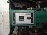
Tried testing with meter, did not get any readings. See attached picture of switch I am testing.
 

Attachments

  • image.jpg
    image.jpg
    24.8 KB · Views: 82
OP
T

Tsquare

Well-known member
Joined
Oct 14, 2013
Messages
283
Location
San Diego
When I connected the power and turned the switch on it blew the breaker - any other thoughts?
 

drivesitfar

Well-known member
Joined
Oct 23, 2013
Messages
36,040
Location
Pacific Northwest
TS: sounds like you have a power wire touching a ground wire or ground. check wiring to see that no wires are touching. can you get pictures of the wires instead of just the switch and post them?

also if tripping the breaker it might have a slight flash or melted wire where it touched ground so get a bright light and check closely.

good luck
 
OP
T

Tsquare

Well-known member
Joined
Oct 14, 2013
Messages
283
Location
San Diego
TS: sounds like you have a power wire touching a ground wire or ground. check wiring to see that no wires are touching. can you get pictures of the wires instead of just the switch and post them?

also if tripping the breaker it might have a slight flash or melted wire where it touched ground so get a bright light and check closely.

good luck

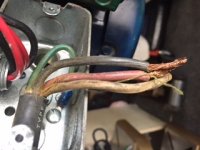
This is from the plug.

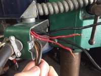
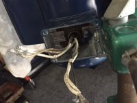
Couldn't see where the wire was shorting. Hope these photos help.
 

Attachments

  • image.jpg
    image.jpg
    28.1 KB · Views: 73
Last edited:
To avoid these ads, REGISTER NOW!

mrjaw14

Well-known member
Joined
May 22, 2012
Messages
1,958
Location
Nashville, TN
That plug looks like it has 4 wires, two hots, a neutral, and a ground. Is this a 120v or 240v unit? They will be wired differently
 

GETRIDAONE

Well-known member
Joined
May 21, 2013
Messages
1,549
Location
Auburn, GA
If the motor is a dual voltage 120/230 the wires coming from the motor have to be paired together to run on one or the other. Look to see if there is a diagram on the motor or inside the junction box cover where the wires come out. There is a numbered tag on each wire and they have to be twisted together according to the diagram.
Just something else to check !
 
OP
T

Tsquare

Well-known member
Joined
Oct 14, 2013
Messages
283
Location
San Diego
If the motor is a dual voltage 120/230 the wires coming from the motor have to be paired together to run on one or the other. Look to see if there is a diagram on the motor or inside the junction box cover where the wires come out. There is a numbered tag on each wire and they have to be twisted together according to the diagram.
Just something else to check !

Their correct for 115V
 

DSLTRK

Well-known member
Joined
Jan 7, 2012
Messages
1,118
Location
PHELAN, CA
The two reds and two black wires are from the switch.

Hi,

I wish I was there to help you, but based on your pictures, you have a 220v(240v) SO cord as your line feeding in. That cord does have a neutral, so you MAY be ok if you need a neutral, as I have no idea how the SO cord was wired to the receptical. Neutral conductors are white or grey. Hot conductors for low voltage are Blue, Black or Red. Green for Ground.

The switch you have is a stop start switch to be used for 220v. If the original switch is indeed 220v for the machine, chances are the motor is 220v. However, looks like somebody painted over the motor specification tag. DON'T ASSUME ANYTHING WHEN DEALING WITH ELECTRICITY.


If the motor is only 120v, you can only use one pole (one wire in and out) of the 220v switch. You cannot switch a neutral conductor per the NEC. As others have said, you need to perform a continuity test with either an ohm meter or voltmeter.

I cannot determine the voltage of the motor based on your pic.


In short, since I and other knowledgeable members are not there to help physically test the circuit for continuity/etc, best you get a local LICENSED electrician to help you out, NOT a HANDYMAN, NOT a "Friend".

You have already popped a bkr once, you may end up damaging your nice drill press.

Best of luck,

-Steve
 

drivesitfar

Well-known member
Joined
Oct 23, 2013
Messages
36,040
Location
Pacific Northwest
TS: I'm sorry i didn't see your pictures until today because yesterday i was a bit busy preparing for company. it looks like others have your back and i tend to agree that you have a 220 wire coming in from your plug. can you post pictures of the plug?

also has the DP ran prior on 110 v that you've seen? some machines like our Craftsman block grinders for instance can run on 110v and by switching a few wires the same machine can run on 220v.

if you want to run it on 110v it might be as simple as swapping out the old plug with a new 110v that you could steal from an old computer or printer if you have one or less than $15 online or at the store.

good luck
 

uart

Well-known member
Joined
Nov 17, 2011
Messages
1,226
Location
Australia
When I posted yesterday I thought it was a simple rocker switch, no a start/stop arrangement. Testing a rocker switch is easy because both sides of the switch are symmetrical, however the start/stop arrangement might not be as simple as just measuring continuity.

I'm familiar with the start/stop circuits on larger industrial equipment, but recently I notice a lot of small home tools also have been coming with the start/stop arrangement. Does anyone know if these are they all electromechanical in nature (like in industrial equip), or are some of the small equipment ones just a mechanical latching device? I'm not sure.

If they are just simple mechanical latch/release devices then yeah, testing them would be as easy as testing a simple rocker switch. If however it's electromechanical (as in relay/contactor) then I would have thought it would have separate ac "power in" and "power out" (aka motor) connections. So just knowing that there are "two red wires" for example might not be enough information. You'd need to know which was power-in and which was motor-out.
 
Last edited:
To avoid these ads, REGISTER NOW!
Top Bottom