To avoid these ads, REGISTER NOW!

Need your $.02 on design

GarageEnvy

Well-known member
Joined
Nov 17, 2009
Messages
1,282
Location
Fresno
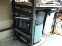
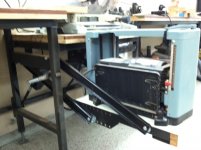
I'm building a pull out/up planer lift to go under my bench. We've got something similar in the kitchen for our mixer so I stole a lot of the design from that. However, the lifting and locking it in place has got me a bit stumped. I've considered using springs, counterweights, garage door torsion springs, snowmobile torsion springs and gas liftback struts. I'm hoping someone has done something like this and has a recommendation. Second, I need a good suggestion on locking it in place. I've thought about some sort of lever with extending rods. I want it to catch on both sides and I want it safe enough that it can't be released if I bump it. Right now the best I've come up with is a rod through the tray into the uprights. That binds it but ideally I'd like something that went into the workbench frame to stabilize it as well. The problem is that there isn't an upright on the right side (trash can location). All ideas welcome.

DSC07931.jpg


DSC07932.jpg


DSC07930.jpg


DSC07934.jpg


DSC07933.jpg
 
To avoid these ads, REGISTER NOW!

srmofo

Well-known member
Joined
Oct 15, 2009
Messages
6,161
Location
SW ohio
A quick easy way is to make some detachable legs. Just weld a couple of pipe stubs an inch or 2 long onto the bottom or sides. Just make sure they will be clear of the hinges. Place them on the side furthest away from the table. Then take some pipe of a smaller diameter and the correct height to use as legs.

Another way would be to place the legs against the wall (or brackets welded onto your nice bench) and have them keep the planner suspended by not allow it to swing inward.

The last one I have is to drill some holes through the welded square the planner sits on. Drill another hole through the "legs" of the swing in the appropriate spot with it fully extended and place a hitch pin through it. Repeat on the other side /other legs.

Anyway you choose I would add some springs and/or struts to assist in lifting it.
 
OP
G

GarageEnvy

Well-known member
Joined
Nov 17, 2009
Messages
1,282
Location
Fresno
Thanks for the help. I had not considered the use of legs and I may go that route. Clearance is a bit of an issue. This is just barely (1/4" wide enough to fit my planer and I already used the narrowest trash can I could find. Getting the geometry of the swing to make sure it cleared was a little tricky too and only left me with about 2" under the platform. The legs would have to stow under the platform.
 

smschriefer

Well-known member
Joined
May 28, 2009
Messages
842
Location
Yorktown, VA
I'm not sure how to explain this idea and I hope you understand my idea. What about a T-handle coming through the front of the base that you twist to move two bars that would support the sides. Similar to a garage door handle/lock. But add a spring to force the pins to the extended position. This would force you to twist the handle to secure and release the pins. You would have to overcome the friction/weight from the tool as well as twist the handle that would have a spring load on it. Heck, if you wanted to, you could add extra security by installing manual push pins on each side once you have it secured.
 
OP
G

GarageEnvy

Well-known member
Joined
Nov 17, 2009
Messages
1,282
Location
Fresno
The T-handle idea is almost exactly what my initial thoughts were. I will have to add some vertical support on the right side for it to catch. I had not thought of the springs but was considering some sort of pin to lock it in place.
 

smschriefer

Well-known member
Joined
May 28, 2009
Messages
842
Location
Yorktown, VA
I can't tell from the picture how high the planer sits in the frame. My thought was to route the pins through the holes you have in the angle iron side rails and through the front support arm - no need for any additional support. It appears that when the table to operational height, these two intersect. You could drill a second set for manual pins to be inserted. Also, if you used a knob instead of a t-handle, your chances of accidentally turning it would be very negligible.
 

Mmfh

MEMBER EMERITUS
Joined
Oct 8, 2011
Messages
1,423
Location
Portland Oregon
I don't really see how springs would work, don't see a good place to hook them up so they work both up and down.

What about struts on each side in the back, like you see on car hoods. Take one of those off a heavy hood, put one on each side up under the cabinet.

Pull it up, its held there, push it down, it goes in slowly because of the struts.

Just a stupid idea.

Mm
 
OP
G

GarageEnvy

Well-known member
Joined
Nov 17, 2009
Messages
1,282
Location
Fresno
I came to the same conclusion with the springs. It's definitely doable but I am still trying to squeeze in a drawer in this space after I'm done with the lift. I could have done springs to the top part of the workbench but it became too complex and cumbersome. I have ordered two struts from Ebay with 150 pound force. My mounting point doesn't have much leverage so even with the 300 pounds of force it will be interesting to see how balanced it is. The struts do allow me to pull it past straight vertical and gain another 2". More updates to come once the struts arrive.
 

BradTx

Well-known member
Joined
Oct 5, 2011
Messages
565
Location
Houston, TX
There are several makers of these mixer shelfs that store large stand mixers while not in use. You might consider finding a local kitchen supply and examining one close up. Then just scale it up for your needs.

revashelf_ras_ml_hdcr_a.jpg
 
OP
G

GarageEnvy

Well-known member
Joined
Nov 17, 2009
Messages
1,282
Location
Fresno
We have that exact (Rev-a-shelf) mixer lift in our kitchen. The swing is not large enough to pull the planer out from underneath the bench. Even if it was, it's not rated for enough weight so extending the arms is not really an option. It did help having one around for designing mine though.
 

porphyre

Banned
Joined
Sep 2, 2009
Messages
1,321
I'm sure you already thought of this, but remember to include a little extra room in your weight calculations for the wood you run through the planer. Especially if you don't have large infeed/outfeed tables, a large percentage of the weight of the workpiece will be supported by the planer and therefore your springs/struts/etc.

Good luck. It looks like it will be super trick when you get it done!

Edit - Thinking about it, you may be able to solve the weight problem with a fold-down leg. Use springs/struts/etc to raise the planer, then drop the leg once it is at working height.
 

postrucks

New member
Joined
Aug 10, 2011
Messages
1
Not as much fun but a whole lot less thinkin, why not make it easy on yourself and put that planer on a stand with wheels (lockable) that roll out from under your bench. You can postion it where ever you need it and it is rock solid.
 
OP
G

GarageEnvy

Well-known member
Joined
Nov 17, 2009
Messages
1,282
Location
Fresno
I did actually give this some thought. I really didn't want to use one of the larger/taller holes in the workbench as I've got other plans for those spots. The height in the lower section is only 29" which puts the board height through the planer near 15" off the ground. Also the spot is only 17" wide so I worried it might be top heavy.

The tray will lock in place in the up position and won't rely on the struts to hold it up.

All good thoughts and I appreciate the input.
 

cvorkian

Active member
Joined
Sep 13, 2010
Messages
32
Location
NORCAL
I messed around a bit with a cantilever slider type of design.

When the shelf/machine is at bench top height, simply push it straight in to the top (travel is about 5"). Accomplished this by making the 4 upper pivot mounts solid studs, sloting the arm the platform hangs from by 6." Weld channel on the inside where the hanging arms can slide into when at bench height.

I can't find the pictures or drawings, and no longer have the cabinet...

Clear as mud???
 
To avoid these ads, REGISTER NOW!
OP
G

GarageEnvy

Well-known member
Joined
Nov 17, 2009
Messages
1,282
Location
Fresno
I'll admit I read it at least twice and thought about it for a second or two but I do understand the design and I like it. If my chop saw wasn't sitting right on top of this space I'd probably use it. As it is, I think I'll end up chopping the overhang back a bit on the chop saw station for clearance. Thanks for the great idea.
 

hawkeye2

Well-known member
Joined
May 22, 2006
Messages
135
Put to spring loaded pins through the top of the angle iron 'tray' that will pop into holes in the front swing arm. If you put them in the right place, you can have the pins engage holes in the back swing arm to lock it in the stored position. Connect a cable straight across from side to side connecting the pins together. Add a cable from the center of this cable, put a handle on the other end, and fab a holder to keep the handle near the front. Pull the handle to release the pins, raise the planner, let go of the handle to lock the pins. Hopefully this makes sense.... Might be easier to build than explain.
 

tarbellb

Well-known member
Joined
Apr 17, 2011
Messages
5,766
Location
Oregon
in reality i bet you find that the supporting arms will be under serious load with the planer and work material being supported.
i would consider legs. a planer is already a serious machine, you dont want that thing going awol mid plane.

is the space to the left a option at all?

if so, i would build a one piece set of legs that pivot out from the left opening. if you used a double hinge, and wheels on the bottom you could pull the planer out and up to swing the legs underneath?

you definitely have a very tight space and a lot of weight to sneak anything into that area.
 

Jack Olsen

Super Moderator
Staff member
Joined
Mar 22, 2009
Messages
6,678
Location
Los Angeles
I haven't read all the other responses, so this might already have been suggested.

But if you put a sturdy (reinforced steel) door in front of it -- what if that door supported the platform when it was in the up position? In other words, the door swings out, past 90°, the mechanism goes out and up, then the door comes back to like 75° with the weight of the planer coming down to rest on top of it.
 

JSBriggs

Well-known member
Joined
May 10, 2009
Messages
1,041
Location
Auburn CA
I've got a steelcase desk with the swing out typewriter shelf. Ill see if I can get a couple pics of the mechanism tomorrow.

-Jeff
 

machine_punk

Well-known member
Joined
May 14, 2011
Messages
2,540
Location
Napa Valley, California
What about an electric linear actuator...attached to the center back of the planer shelf and a bracket on the back of the bench...push a button and the shelf swings smoothly in place.

Or, a similar idea with the gas struts from a car's hatchback...set them up with maximum force in the 'open' position, then use body weight to lower the tool and 'lock' it at the bottom.

Or a pneumatic over hydraulic cylinder to raise the shelf (I think HF even sells these...like the air over hydraulic cylinder for a small cherry picker engine hoist).

Kev
 

RivennHewn

Well-known member
Joined
Jun 4, 2011
Messages
10,378
Location
PNW
I, and by 'I' I mean everyone, will be curious to see what you come up with.

No pressure.
 
OP
G

GarageEnvy

Well-known member
Joined
Nov 17, 2009
Messages
1,282
Location
Fresno
Jack, I thought about a swing out leg like the ones used on drop leaf tables. One of the 3' strong hold cabinets I bought had two shelves that were cut off. As you know, they're pretty strong. There will be a door. I just have to figure out if it needs addition support over the rods.

Linear actuators! Wow, I'm really looking for the Jack Olsen solution here. As you probably can tell from the photos, this is just old scrap metal I'm using up. One of the great things about GJ is no matter how carried away, over the top you get with a simple project, someone will ramp it up even further. I can't say it didn't cross my mind. It's just not in the budget. I will confess that I looked at the OMC outdrive on a boat the other day with the thought of robbing the tilt mechanism.

Struts are en route so the project is waiting for the Fed Ex guy.
 

cvorkian

Active member
Joined
Sep 13, 2010
Messages
32
Location
NORCAL
SO, phase two of the cantilever design:
Attach a channel to the cabinet side rail or top rail (underside counter top).

Within that channel, you place bar stock or tubing that will slid out to support the tray when upright... it doesn't have to be full length since the tray is solid metal.

As with my last post, the cantilever holds the tray at working height... at what ever your current design has it set for.

THIS design is just a simple addition of a "sleeved" channel with tubing... limit the cantilever with a simple screw or bolt welded onto cantilever section.


OR..... hing a triangular "wing" on either side of the cabinet. When tray is up, swing hinged "wing" into place, similar to the door idea above....

Hopefully this makes sense.

Post the progress....
 

cvorkian

Active member
Joined
Sep 13, 2010
Messages
32
Location
NORCAL
Join Date: Sep 2010
Posts: 7 Re: Need your $.02 on design

--------------------------------------------------------------------------------

SO, phase two of the cantilever design:
Attach a channel to the cabinet side rail or top rail (underside counter top).

Within that channel, you place bar stock or tubing that will slid out to support the tray when upright... it doesn't have to be full length since the tray is solid metal.

As with my last post, the cantilever holds the tray at working height... at what ever your current design has it set for.

THIS design is just a simple addition of a "sleeved" channel with tubing... limit the cantilever with a simple screw or bolt welded onto cantilever section.


OR..... hing a triangular "wing" on either side of the cabinet. When tray is up, swing hinged "wing" into place, similar to the door idea above....

Hopefully this makes sense.

Post the progress....
 

Frank The Plumber

Well-known member
Joined
Feb 19, 2011
Messages
2,644
Location
Chicago.
I think I would have just made a table that could tuck into the alloted space. It seems that you now have a fairly dangerous device here that is capable of cutting something off. The machine itself is heavy, Mine is at least 70 pounds, on average I run a 30 pound board into it, there can be a lot of vibration and travel as well. Lifting the entire machine and now the added steel structure is going to become tediuos and possibly consume time at critical points, when you need it, it will break and just piss you off. And in the end you still have a device that requires lifting even if you try to do an assist. Add to that the fact that the unit requires legs to keep it from leveraging on the main table and it's just getting way too complex to keep truly safe.

I think I would have made a table that could tuck into the space, had a storage space under the table for this device, put it on small wheels designed a fastening stabilizing situation in that area to shore the unit up and keep it from moving while in use.

With a table you could use multiple machines on the same platform, you could even make a small drawer for the knives and attachments. This device is looking like it will cut your hand off. Sorry.
 
OP
G

GarageEnvy

Well-known member
Joined
Nov 17, 2009
Messages
1,282
Location
Fresno
Frank, you might be right but I'll know in a day or two. The struts arrived last night. I used an online calculator for how much force would be required to fully lift the planer but I also used a whole pile of assumptions (guesses) in the calculations. In the end I just bought the most powerful strut in the size that would fit. Unassisted you're right about the danger. In fact it slipped off the stand while I was working on it and wildly swung into the hole. I plan on adding a door to the front. If it turns out to be unstable I'll work the door into a support. If it's still dicey I'll scrap the whole thing and write-off the experience as a geometry lesson.
 

charle10

Well-known member
Joined
Jun 1, 2009
Messages
209
Location
Commerce, Mi
Could you put a cross bar about 1/3 to 1/2 way down on the back swinging arms, then put a cross bar on the table frame, then attach a scissor jack between both cross bars. That way you could just crank it up into position, and when it needs to go back, just screw it back down?
 
OP
G

GarageEnvy

Well-known member
Joined
Nov 17, 2009
Messages
1,282
Location
Fresno
Well, I finished this project and finally had a chance to put it to the test. I ran some 8/4 9" wide African Mahogany though it. The boards were 6'6" to 10' long and it was stable. I tried a couple of lever style pin locking mechanisms that failed. What ended up working well was a simple pin under the channel. The struts are 150 pound pressure and there are two of them. The mounting location for the strut allows the tray to rotate back beyond vertical to hold it under the bench but it created a problem. The struts made ithe first part of the stroke (down to vertical) difficult so I had to add some helper springs. Stop blocks at vertical would have worked too but then I would have had to move the whole mechanism rearward to get it under the bench. It was made from scrap metal laying around so the total cost was under $50 with the struts and springs. The struts are at about a 40 degree angle when extended and it is weight neutral. It will rest in any position along the arc. It can easily be raised with one hand so I'm pretty happy with the results.
 

Attachments

  • Planer lift 1.JPG
    Planer lift 1.JPG
    106.2 KB · Views: 38
  • Planer lift 2.JPG
    Planer lift 2.JPG
    136.2 KB · Views: 37
  • Planer lift 3.JPG
    Planer lift 3.JPG
    112.9 KB · Views: 41
  • Planer lift 4.JPG
    Planer lift 4.JPG
    114.8 KB · Views: 38
  • Planer lift 5.JPG
    Planer lift 5.JPG
    100.8 KB · Views: 37
Last edited:
To avoid these ads, REGISTER NOW!
Top Bottom