To avoid these ads, REGISTER NOW!

Needle bearing to shaft preload/clearance?

myredracer

Well-known member
Joined
Nov 1, 2015
Messages
557
Location
Langley, BC
I had a custom performance engine for a vintage car built about about 10 years ago by a guy who ran a shop in the US and later sold the business which is now in Europe so I can't ask the original builder or shop anything. A needle bearing was installed in the end of the crankshaft for the (manual) transmission input shaft. These engines normally have a bronze bushing.

Yesterday I tried to install the engine in the car after restoring the car for a couple of years. The shaft would only go part way into the bearing. After much head scratching I realized that the shaft diameter is exactly the same size as the bore in the bearing and it's gotta have some kind of working clearance. The bearing bore is a nominal 12 mm size and the shaft measures 12.00 mm. I'm just not finding a simple answer on google. I've installed lots of ball & tapered roller bearing but never a "straight" through needle/roller bearing and they're a LOT different it seems and can involve some complex math. The best I can figure it requires a class "h5" clearance but that's as far as I can figure it out and don't see how that relates to a shaft diameter.

So how do you determine the preload/clearance/tolerance needed so I know what dia. the shaft needs to be? This bearing normally only rotates on the shaft when the clutch is depressed if that makes any difference. The bearing is a drawn cup "HK 1216.26RS" made by INA. What I need to do is take the shaft into a machine shop and get the end machined down a bit. I cut the threads off an old 12 mm bolt and pushed the unthreaded portion of it which is 11.87 mm dia. into the bearing, and it slides in and rotates nicely but just don't know if that's too tight or too loose.

INA_INTERNATIONAL_00071252.jpg
4263659.JPG
 
Last edited:
To avoid these ads, REGISTER NOW!

Worsedog

Well-known member
Joined
Mar 2, 2008
Messages
1,523
Location
Central FL
This:

So, verify this: the pilot tip and the bearing or bushing should have about .0005 to .003 clearance. Not to be confused with an interference fit which is a no go. This check can be preliminarily checked with the bearing or bushing not installed in the crank but MUST be verified after it is installed in the crank because the inside diameter will shrink.

Was shamelessly stolen from here: https://www.bowlertransmissions.com/new-manual-transmission-fitment-installation-guide/
 

SGKent

Banned
Joined
Feb 12, 2010
Messages
1,959
Location
Citrus Heights CA
did you slide the clutch disk onto the input shaft to make sure it slides freely? I've seen where the pilot bearing wasn't where the hang up was because of that. As others said, put the pilot bearing onto the shaft first. There is a chance that the crush is making the bearing smaller too.
 

BillK

Well-known member
Joined
Aug 24, 2006
Messages
9,421
Location
Beautiful Southern Maryland
If the shaft goes part way in but not all the way I am thinking that the "hole" in the crank is not the same size all the way in or was not cleaned out all the way before pressing the roller bearing in.

I will be honest with you, if it was me I would take the roller bearing out and install the old school bushing. A lot of newer cars use roller bearings that are pressed into the flywheel and pretty much every time I see one it has turned into a ball of rust :(

Also, this is going to sound crude but try tapping the shaft some and wiggle it around and try to force it into the bearing. It just might loosen up once you do that.

If you do decide to have the shaft cut down it will have to be done with a grinder, not a lathe. The shaft is too hard to get a nice cut with a lathe. A crankshaft grinder would do the trick or a lathe with a tool post grinder.
 
OP
M

myredracer

Well-known member
Joined
Nov 1, 2015
Messages
557
Location
Langley, BC
Thanks for the comments.

The clutch disc slides just fine on the splines so no issue there.

I am wondering if why the 12.00 mm dia. shaft only goes in part way is because the rollers get tilted slightly and are binding against the shaft?? The shaft seems to vary in dia. slightly from end to the other by about 0.01 mm or so. Nevertheless, there is supposed to be "some" amount of clearance between the bearing and shaft and the way it is now, there is zero clearance. Maybe even less than zero if, as the info. in the link Worsedog posted, the bearings shrink slightly when tapped into a hole.

The article in Worsedog's link says the clearance for pilot bearings should be 0.0005" to 0.003". According to my telescoping gauge, I measure the bore dia. to be 11.94 mm, but I can't tell if the gauge is touching between the rollers or right on top of them. It seems like I'd need a pin gauge set to accurately get a measurement which isn't cheap. Not an option for a one-time need so looks like I may need to get the engine to a shop.

I'd did try lightly tapping the shaft into the bearing but got too tight. It's def. too large in dia. to me.

Changing out the bearing for an original bronze type won't work as the hole in the end of the cranked was drilled to accommodate a bearing. I suppose I could get a custom bushing machined, but that's just more work and time and expense...

I'll call a machine shop tomorrow.
 
Last edited:

SKFengineer

Well-known member
Joined
Apr 5, 2018
Messages
45
Location
Macungie, PA
I’m traveling so I don’t have all my typical resources with me but the INA website should tell you what clearance is expected. If not you can go to our SKF website and check, off the top of my head I would expect somewhere in the range of 25-40 microns before installation in the crank but after installation it will lose maybe half of that. I agree with the above if goes halfway and stops that’s bad. I also agree the bore holding the bearing is suspect. Regardless of the bore condition I would also replace the bearing if it’s been sitting a long time open. Bearing steel has a high level of carbon for hardness which results in a material that will rust quickly if not protected. This last statement is also related to an earlier comment about using a bushing... The needle bearing is superior IF it’s kept lubricated and sealed, the bushing will perform better in the long run if contamination is expected. Finally whether you use a bushing or a needle bearing the condition of the pilot bore in the crank needs to be straight and of the correct diameter, both bearings types will fail more quickly if their seat is out of tolerance.
 

matt_i

Well-known member
Joined
Mar 14, 2008
Messages
10,796
Location
SE Michigan
My big concern is that with the INA needle bearing, is the shaft is the inner race of the bearing (!) If the tip which engages the needles isn't appropriately hardened just like the bearing rollers they are going to wear it out (groove, lots of metal swarf to further jack up the works) in short order. If a file can cut it (like on a chamfer), its probably not hard enough, in my opinion.

The bronze plain bearing would be a lot more forgiving as a bearing material to a medium carbon steel shaft. Knowing that the bronze was put in there by the OEM, I would personally follow that same track on rework.

If you do grind the shaft, I would polish it, afterwards, in the same direction of rotation.
 

SKFengineer

Well-known member
Joined
Apr 5, 2018
Messages
45
Location
Macungie, PA
I would not recommend modifying the shaft in anyway. From my keyboard I would guess it currently has the correct shape, hardness and finish.
 
OP
M

myredracer

Well-known member
Joined
Nov 1, 2015
Messages
557
Location
Langley, BC
I would not recommend modifying the shaft in anyway. From my keyboard I would guess it currently has the correct shape, hardness and finish.
I'm a little confused on what I've got and what the original engine builder intended. Was the builder simply not thinking? I had a lot of performance things done to the engine like stroker crank, forged rods & pistons, larger valves, titanium valve spring retainers, ported head, balancing, blah, blah, blah. As part of the build, a pilot bearing was recommended but I believe not many customers would have had the same thing done I did, if any. My build was somewhat unique and there aren't others out there to ask what they did. I had another person rebuild the transmission and neither would have known what the other did to ensure the two went together okay.

The stock dia. of the input shaft is exactly 12.00 mm. Needle bearings come in standard nominal sizes. It's not like I could remove the bearing and install one with an under-sized bore by a few thou. to get the clearance I need. Seems like machining the shaft is the only option. Yes, I would get it polished. Historically speaking, the bronze bushings in these engines don't have a long lifespan and end up rather sloppy. In a high HP engine and with "spirited" driving on the street, proper tolerances between engine and transmission would have to be critical...

I will def. talk to the machine shop about the bearing in detail and especially about it sitting unused for 10 years. Good info.! It was in a closet inside our house the whole time and kept warm & dry. I would only need to reduce the input shaft dia. by a few thou. and would the hardness depth of shaft be enough for that?

One thing for sure, I can't afford to have a $20-30 pilot bearing fail and cause some very expensive drivetrain damage.
 
Last edited:
OP
M

myredracer

Well-known member
Joined
Nov 1, 2015
Messages
557
Location
Langley, BC
I’m traveling so I don’t have all my typical resources with me but the INA website should tell you what clearance is expected. If not you can go to our SKF website and check, off the top of my head I would expect somewhere in the range of 25-40 microns before installation in the crank but after installation it will lose maybe half of that. I agree with the above if goes halfway and stops that’s bad.
It seems like the thing to know about these needle bearings is that the bore size can shrink after installation and you have to measure what you've got. I was looking on the INA and SKF for a fixed number required for the shaft dia. but now I see it doesn't work that way.

When I push the shaft in and it stops, it's not like a hard stop. It's kinda like it starts to bind the farther it goes in until it gets to a point where I need to tap it out. There's a should on the hole that was drilled in the crank to keep the bearing at the right depth into the crank. I was initially wondering if the dia. of the reduced dia. section of the stepped hole is a tad too small. I can't see in there very well and a telescoping gauge isn't helping me.
 

MattT

Well-known member
Joined
Feb 20, 2010
Messages
3,201
Changing out the bearing for an original bronze type won't work as the hole in the end of the cranked was drilled to accommodate a bearing. I suppose I could get a custom bushing machined, but that's just more work and time and expense...

Looks like that needle brg is 12mm bore x 18mm outside diameter x 16mm long. This bushing should be a drop in replacement.

https://www.mcmaster.com/6658k18

Either way there is something wrong with the current bearing and you need to get it out of there. Likely either the crank bore machined wrong or bearing was installed improperly. If the bore is wrong you can either get it reworked for a new bearing or drive a bushing in and ream it.
 

SGKent

Banned
Joined
Feb 12, 2010
Messages
1,959
Location
Citrus Heights CA
I have a hobby of restoring VW bus engines. The type 4 engines (North American late buses, Porsche 912E, 914-4, and VW 411/412 as well as some industrial military engines) have a similar pilot needle bearing. They go bad all the time. In my career I've replaced Oilite, bronze, sealed ball, and needle pilot bearings. None are forever. I think this mod is becoming an overkill situation that has the potential to go down hill further as soon as the size and hardness of things start getting changed. Also I would not be getting my advise here on the garage forum although many car and machinists are here who are quite capable. I'd be on an engine builder or racers forum where others have gone thru this mod. There are many out there and some of the people here are members there too. I don't even recall the engine type being mentioned in this thread. And FWIW lots of "engine builders" f-up custom engines. I worked for a shop that built Cosworth racing engines, Indy bound engines, and even some winning vehicles for Al Unser Jr. I've repaired many other shop's screw-ups on custom and stock engines. It's like any trade. Just because a nail is holding two pieces of wood together it doesn't mean it is in the right place, or is even the right gauge nail.
 
Last edited:
OP
M

myredracer

Well-known member
Joined
Nov 1, 2015
Messages
557
Location
Langley, BC
The solution isn't going to be as easy as I thought, pffft...

I went to a couple of machine shops this morning. Both said they don't have lathes and just do regular engine rebuild work. They both said try a transmission shop so I tried two nearby. First said nope, can't help. Second said the same but gave me the name of a local transmission shop that could handle that sort of work. Turns out that shop is a highly specialized transmission shop that does specialty transmission work including making their own parts as needed. I had no idea they existed and the guy I talked to said they're a well-kept secret.

The shop manager then took me to a shop across the street that does specialty machine work for the forestry and mining industry. A guy there tested the hardness of my input shaft and it's nowhere near the hardness it needs to be to used as a raceway running in a needle bearing. Lovely. The transmission shop could make a new shaft from scratch but after all the setup costs included, would cost something like $4K! He recommended going back to a bronze bushing like what was originally used by the car manufacturer. Obviously a bronze bushing wouldn't hurt the steel shaft.

The trans. shop guy said he could easily make a new bronze bushing but that I would have to tell him the dimensions of it because he would NOT measure it up for me, even though he could. Liability reasons I guess.

It looks like I will be pulling the bearing out regardless. Another thought I had is what about turning down the shaft and installing a sleeve on it with appropriate hardness?
 
OP
M

myredracer

Well-known member
Joined
Nov 1, 2015
Messages
557
Location
Langley, BC
I don't even recall the engine type being mentioned in this thread.
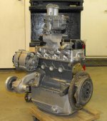
For those wondering, it's going into a Fiat 600 I'm restoring and building into a replica factory Fiat Abarth 850TC race car from circa 1963. Original 633 cc engine made 22 HP. My performance engine will have about 90 HP. The engine is from a later Fiat 850 (same external dimensions) of 903 cc capacity and it's got a crank from an Abarth Autobianchi A112 made by Fiat (only ever sold in Europe). The 903 cc block was modified to take the A112 crank and it's longer stroke to create 1050 cc. The Autobianchi cars were front wheel drive and did not have a pilot bushing or bearing while the fiat 600-based cars are rear engine, rear wheel drive.

The engine builder was a brilliant guy on these engines and used to also sell a wide range of all sorts of cool aftermarket engine parts. But he sure didn't have his thinking cap on when he decided to go with the needle bearing.
 

Attachments

  • DSCF0144 (2).jpg
    DSCF0144 (2).jpg
    113.9 KB · Views: 29
  • DSCF0136 (2).jpg
    DSCF0136 (2).jpg
    149.4 KB · Views: 28
Last edited:
OP
M

myredracer

Well-known member
Joined
Nov 1, 2015
Messages
557
Location
Langley, BC
Looks like that needle brg is 12mm bore x 18mm outside diameter x 16mm long. This bushing should be a drop in replacement.

https://www.mcmaster.com/6658k18

Either way there is something wrong with the current bearing and you need to get it out of there. Likely either the crank bore machined wrong or bearing was installed improperly. If the bore is wrong you can either get it reworked for a new bearing or drive a bushing in and ream it.
Thanks for that link! I did not think there could be an off the shelf bushing that would work. Only $1.80 too!! That would sure make things easier and I would just have to ream it out. Can a pilot bushing be reamed out after it's installed or can it be reamed before installation? Depending on how much the bushing would have to be opened up, may I can just use a brake cylinder hone myself?

Yeah, I'm def. gonna pull that stupid bearing out.
 
Last edited:
To avoid these ads, REGISTER NOW!

turbodave

Well-known member
Joined
Apr 30, 2012
Messages
673
Location
IL/WI
I'm installing needle pilot bearing #3 into my truck. The original was a ball of rust at 80k miles, the second one fell apart when pulling the trans to replace a throwout bearing at 125k. Now putting it back together and I wasn't happy with how the surface of the input shaft looked so after looking for a new shaft and not having any luck I found this: https://www.fitzall.com/bearings.php

Basically it's a hardened bearing race that is pressed onto the input shaft and then I install a bearing with a larger ID.

I doubt any of their off the shelf options would fit what you have, but maybe there is a hardened sleeve like this out there that you could press onto your shaft once it's machined down.
 

SKFengineer

Well-known member
Joined
Apr 5, 2018
Messages
45
Location
Macungie, PA
Sorry I was flying in the air during the middle of the day. Given what I see in all the threads I think you might be right to use the bronze bushing but if you want I can check some books tomorrow so see if my SWAG was close today. What I can do is double check the hardness requirement and also get you an “under the roller diameter” spec. This specification would pretty much be the expected id of the rollers for that bearing. INA is clearly a different company than us but the values should be close as they are all metric ISO dimension based bearings.
 
OP
M

myredracer

Well-known member
Joined
Nov 1, 2015
Messages
557
Location
Langley, BC
Sorry I was flying in the air during the middle of the day. Given what I see in all the threads I think you might be right to use the bronze bushing but if you want I can check some books tomorrow so see if my SWAG was close today. What I can do is double check the hardness requirement and also get you an “under the roller diameter” spec. This specification would pretty much be the expected id of the rollers for that bearing. INA is clearly a different company than us but the values should be close as they are all metric ISO dimension based bearings.
Thanks, any help would be appreciated.

I tried to remove the bearing using the grease, shaft & hammer trick but couldn't get it to budge. In the process, I damaged the bearing and little bits of plastic came out, sigh. Nobody in town has a pilot bearing puller so now I'll have to get the engine into our truck and to a machine shop. I did manage to remove a bronze bushing out of a spare crank I had laying around and it easily popped out. The outer dia. of the bronze bushing and needle bearing are different. It looks like the bushing from McMaster may be an option but I need to get the old bearing out to see what the actual bore diameter in the end of the crank is.
 

matt_i

Well-known member
Joined
Mar 14, 2008
Messages
10,796
Location
SE Michigan
The needle roller bearing is probably looking for a sub .0005" diametral clearance which is super unforgiving when you are talking about the dowels between engine and transmission case. Couple of thousandths, yes OK but its not going to be a .0005" fit...

A slide hammer setup would be my tool of choice to remove the needle case, probably best a 2 or 3 jaw mini-expanding jaw would be best. But your typical 5 lb 5/8-18 slide hammer is too big. More like a 1 pounder on a 3/8-16 shaft with a 1/4-20 tapped thread for a setscrew.

On the bronze I'd focus on .002" diametral clearance and .0005" press on the OD. More press than that could happen but it can also shrink your diametral clearance.
 
OP
M

myredracer

Well-known member
Joined
Nov 1, 2015
Messages
557
Location
Langley, BC
Just came across a website called crankshaftcoalition.com and on the subject of pilot bushings, they state "You cannot use a roller bearing on a transmission shaft originally designed for a bronze bushing due to different type of heat treatment on the shafts." The test on my shaft yesterday backs that up. I'll definitely be installing a bronze bushing. I can't believe the particular engine builder I used didn't know any better. :mad:
 
Last edited:

SKFengineer

Well-known member
Joined
Apr 5, 2018
Messages
45
Location
Macungie, PA
Myredracer, I would agree with your last post... You said that a local machine shop tested the hardness of the transmission input shaft, what was the result. If it's not at least in the 50's HRC then I wouldn't trust using it with the needle bearing.

Since the engine has been sitting a while it's very very likely the needle bearing removal will be a fight. I would guess the bearing ring is rusted to the crank, use all the rust penetrant you can find... You might need to destroy the cage and roller set to get a better grip on the ring. The plastic you noted during your first removal attempt is likely cage material.

As I said once the bearing is out take your time to ensure the pilot hole is the correct shape and finish if it's tapered or anything the bronze bushing will not last as long as you expect either.

I think it's a moot point but if you still need information on the needle bearing let me know

Good luck
 

QwikKotaTx

Well-known member
Joined
Aug 10, 2013
Messages
967
Location
Seabrook, TX
To get my old pilot bearing out I used a can of computer cleaning spray air to freeze the bearing then a slide puller with an internal bearing puller attached. It was definitely a fight. The old needle bearing did not rotate but I had no idea before I changed out my clutch. The new one went on the shaft without a press fit but I had to draw it in with the engine to bellhousing bolts.
 
Last edited:

SGKent

Banned
Joined
Feb 12, 2010
Messages
1,959
Location
Citrus Heights CA
I raced the 124 spyders for many years. Have worked on many 850s and a few 600s when was a fiat/ alfa / lancia mechanic. FWIW the 850 was a terribly unreliable engine compared to the later 1400 - 2L twin cam motors in the 124 series. A slap hammer and pilot bearing puller is what you need. HF in Bellingham or Mt Vernon should have one, and I suspect a friend of mine in Surrey BC should have one. Both aren't far from you. E-mail me at the contact for members if you can't find one.

https://www.harborfreight.com/slide-hammer-and-bearing-puller-set-5-pc-62601.html
 
Last edited:
OP
M

myredracer

Well-known member
Joined
Nov 1, 2015
Messages
557
Location
Langley, BC
I raced the 124 spyders for many years. Have worked on many 850s and a few 600s when was a fiat/ alfa / lancia mechanic. FWIW the 850 was a terribly unreliable engine compared to the later 1400 - 2L twin cam motors in the 124 series. A slap hammer and pilot bearing puller is what you need. HF in Bellingham or Mt Vernon should have one, and I suspect a friend of mine in Surrey BC should have one. Both aren't far from you. E-mail me at the contact for members if you can't find one.

https://www.harborfreight.com/slide-hammer-and-bearing-puller-set-5-pc-62601.html
Yeah, the 600 & 850 engines didn't last all that long. Mostly I believe, is because the gaskets/seals started to leak oil all over and you were faced with a total rebuild. With the 850 spiders being a sports car, owners tended to wring the sn*t out of them which didn't help (like I did back in the 70s).

I've got a '66 Fiat Abarth 1300/124 I'm restoring. It's based on the 850 coupes. Less than 300 ever made. Has a 124 engine but it's a pushrod out of an early 124 sedan. Very similar to an 850 engine except larger. Using a 124 twin cam in an 850 means the rotation needs to be reversed which isn't easy in a twin cam but used to be done. PBS I believe had a kit or info. on doing it. There used to be a late 60s Abarth Berlina Corsa here (they're based on 600 sedans) and the owner installed a 2 liter twin cam. He raced in local autocrosses and it could do wheelies... :shocking:

Nice to know there's folks around that know something about the old Fiats.
 
OP
M

myredracer

Well-known member
Joined
Nov 1, 2015
Messages
557
Location
Langley, BC
Myredracer, I would agree with your last post... You said that a local machine shop tested the hardness of the transmission input shaft, what was the result. If it's not at least in the 50's HRC then I wouldn't trust using it with the needle bearing.

Since the engine has been sitting a while it's very very likely the needle bearing removal will be a fight. I would guess the bearing ring is rusted to the crank, use all the rust penetrant you can find... You might need to destroy the cage and roller set to get a better grip on the ring. The plastic you noted during your first removal attempt is likely cage material.

As I said once the bearing is out take your time to ensure the pilot hole is the correct shape and finish if it's tapered or anything the bronze bushing will not last as long as you expect either.

I think it's a moot point but if you still need information on the needle bearing let me know

Good luck
Thanks for the reply.

Getting the bearing out was a real beach. :mad: I had to destroy it to get it out but didn't matter. It was stucker than stuck and took a lot of patience and anxiety. Seems like the bore in the crank was simply too small by about a few thou. I talked to a guy that owns an auto shop about 50 miles from here that know these engines. He put me onto a machine shop not too far from home that does a lot of work on various vintage engines. He said to use a grinding stone in a die grinder or dremel and not a rotary burr as that could damage the bore. No evidence of corrosion.

With the outer casing only still stuck in there, after making a bit of a groove I used some freeze-spray to get the casing to shrink enough to be able to get a bit of a lip to slip a chisel (ground down drift) between the casing and crank bore. If I ever had to do this again, I would not cut away all of the outer lip on the casing.

I don't have a bore gauge and used a telescoping gauge and hope I'm accurate enough. I was able to get repeatable measurements within 0.0005" in different positions.

I've ordered a new custom sized bushing at a local specialist transmission machine shop. The guy I talked to was very knowledgeable. Next trick will be to get the bushing in without messing it up. I'm planning to freeze-spray it but not sure whether to tap it in or to press it in (using a modified gear puller) which could be too slow and allow the bushing to cool too soon.
 

matt_i

Well-known member
Joined
Mar 14, 2008
Messages
10,796
Location
SE Michigan
I've ordered a new custom sized bushing at a local specialist transmission machine shop. The guy I talked to was very knowledgeable. Next trick will be to get the bushing in without messing it up. I'm planning to freeze-spray it but not sure whether to tap it in or to press it in (using a modified gear puller) which could be too slow and allow the bushing to cool too soon.

You're probably tired of me replying but what's your interference? I'm going to guess something like an OD/ID of 18-20mm and I'd shoot for .001" of interference. The freezey spray would probably make it so that you can just tap it in with a block of wood. Main thing is to keep it square and that's where a press really helps. A long shaft to help orient the axis of the bushing would help but it would have to be a loose fit on the ID you know .005-.010" diametral clearance or more.
 
OP
M

myredracer

Well-known member
Joined
Nov 1, 2015
Messages
557
Location
Langley, BC
Myredracer, I would agree with your last post... You said that a local machine shop tested the hardness of the transmission input shaft, what was the result. If it's not at least in the 50's HRC then I wouldn't trust using it with the needle bearing.
Oh, and they measured the harness at 40-something, well below the 50s range.
 

MattT

Well-known member
Joined
Feb 20, 2010
Messages
3,201
Can a pilot bushing be reamed out after it's installed or can it be reamed before installation?

Ream after install if required.

I'm planning to freeze-spray it but not sure whether to tap it in or to press it in (using a modified gear puller) which could be too slow and allow the bushing to cool too soon.

Put it in a ziploc bag and throw it in the freezer overnight. Might just push in after that depending on the fit. Even a tight fit should tap in after a good freezing.
 

QwikKotaTx

Well-known member
Joined
Aug 10, 2013
Messages
967
Location
Seabrook, TX
I damaged the bearings trying to tap them in. A bushing should be stronger but I felt more confident using a gear puller to push it in using the drive side of a large socket.
 
OP
M

myredracer

Well-known member
Joined
Nov 1, 2015
Messages
557
Location
Langley, BC
You're probably tired of me replying but what's your interference?
Not at all. Any help and comments are appreciated.


Success! I ordered a new bushing yesterday (Thursday) and they actually machined it the same day. Now that's service!

I got it installed today. I stared at it at it for a few hours and did some other stuff before getting up the courage to do it. I shrunk it using freeze-spray and tapped it in with a brass drift. Went in nicely without a hiccup. The ID did shrink a tad as expected. I used a small dia. drum sander in my Dremel and wrapped some 320 grit sticky-back sandpaper around it. Was able to increase the dia. just enough so the shaft would slide on smoothly. Overall, not as difficult as I thought it was going to be and I didn't damage an engine I have many thousands of $$ invested in (whew).

I even got the engine in today. Very exciting. :) So now it's party time. :beer:
 
Last edited:

SGKent

Banned
Joined
Feb 12, 2010
Messages
1,959
Location
Citrus Heights CA
isn't the 66 1300 a 3 main block engine whereas the 1968 124 engines and later were 5 main block engines? I knew PBS well back in those days.
 

willbird

Well-known member
Joined
Dec 24, 2019
Messages
65
Location
NNWW Ohio
There's a should on the hole that was drilled in the crank to keep the bearing at the right depth into the crank. I was initially wondering if the dia. of the reduced dia. section of the stepped hole is a tad too small. I can't see in there very well and a telescoping gauge isn't helping me.

This brings up a general topic. I would sure hope that they did not "drill" the bore that the bearing is pressed into. Bearing bores and the shaft that fit the inner race of the bearing need to be held to close tolerances.

Diameter and roundness both matter a lot. Most bearings when pressed in/on transfer the defects of the mounting into the bearing.

The bearing mfg typically publish all of the tolerances required for the shaft and housing.

It sounds like perhaps the mounting bore is less than perfect. The correct answer is to remove the bearing and have that issue corrected. That way every transmission you might want to use does not need alteration.

Also if they really messed it up as bad as it sounds the rollers may not roll anyway.

The pilot bearing or bushing should not be heavily loaded enough to fail rapidly IF the transmission shaft is properly aligned with the engine crankshaft.

Sorry I see you have it fixed :). Pressing a bushing in then finishing the ID actually corrects for any defects in the mounting, which is why it was and is often done just that way :).

Bill
 

Doozer75

Well-known member
Joined
Oct 24, 2009
Messages
260
Location
Buffalo NY
.......... The ID did shrink a tad as expected. I used a small dia. drum sander in my Dremel and wrapped some 320 grit sticky-back sandpaper around it. Was able to increase the dia. just enough so the shaft would slide on smoothly. .....

After your Dremel snadpaper trick
now the bore of the bushing is no longer cylindrical
and surface bearing area that is presented to the
shaft that will spin inside it is now greatly reduced,
possibly by half. Also just going at it with a Dremel
you are no longer assured that the ID and OD of
the bushing is concentric with each other or
coaxial with each other. Shortcuts like this are the
usual reason that bushings have premature failure,
and people blame the bushing. All bets are off when
fits and geometry are modified from engineering
specifications. In the game of press fit bronze
bushings, you need to calculate the ID shrink
from the press fitting of the bushing, and specify
the proper ID based on the clearance wanted and
accounting for the shrink that will happen.
I would have made another bushing, now having
learned the hard way about the ID closing up
from the OD press fit. I might be a little biased
as I have lathes and milling machines in my shop,
but the Dremel and sandpaper trick can bite you
or it might not. Not trying to be negative here,
just telling the potential pitfalls of how you chose
to manage your situation, and how said pitfalls
are generally avoided in the engineering world
where fits are everything and there are specifications
to eliminate guessing at variables. Best wishes
with your project.

--Doozer
 
To avoid these ads, REGISTER NOW!
Top Bottom