My first post on my first real garage and I am looking for some suggestions pls.
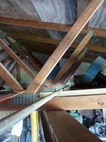
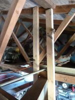
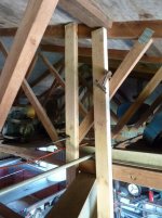
The basics: 19' wide and 25' deep. The back has a 5' deep section across the whole 19' width so the main part of the garage is about 19x20. It has a metal roof and a concrete floor in pretty good shape. Looks like the concrete was done in 1979 and there is a drain in the middle but not sure if it works. The original wood siding looks pretty old and has been covered in vinyl siding on the outside. There is a steel i-beam down the middle that supports the roof. It sags maybe 3-4" in the middle which you might be able to see from the pictures.
I will use it to keep one of my cars in (1996 911 convertible) and do some light engine and mechanical work (brakes etc) and keeping it clean and polished.
My plan so far:
1. New garage door coming in April
2. Have ripped out all the old drywall that was only on one wall where the window and workbench are- there is insulation underneath. I plan to drywall the 2 walls going down the sides. I have left the insulation there but not sure if i will put insulation under the drywall on the other wall. It will not see too much winter work and given i wont be insulating the back wall or roof i dont think one or 2 walls of insulation will make much of a difference. The drywalling is really just so it looks tidier and updated
3. Lighting: i am hanging 3 - 2 bulb T8 32w lights down each side with a 7th light over the work bench on the left. I will have some halogen lights for task lighting when i am working on the car. There will also be one T8 in the 5' wide back room which will be just for storage.
4. Electrical: will have 2 sockets by the panel by the front door, 2 more in front of the work bench, 1 by the back wall and 1 on the other side wall
5. Floor: leave it a is
6. Roof: it does sag a bit and as you can hopefully see from the pictures, the weight is resting on the shims on the ibeam. The whole thing looks a bit half assed but what risks am i running if i try and use jacks to raise it slightly and reshim it. Not exactly sure how i would do this and whether its even worth tackling
7. The workbench is an old cabinet from my wifes work. Its pretty solid but will likely put a 3/4" inch piece of plywood on the top before i bolt on a vice (suggestions on vice type?)
Thats about all i can think of so would appreciate any advice or suggestion.
Many thanks!!
The basics: 19' wide and 25' deep. The back has a 5' deep section across the whole 19' width so the main part of the garage is about 19x20. It has a metal roof and a concrete floor in pretty good shape. Looks like the concrete was done in 1979 and there is a drain in the middle but not sure if it works. The original wood siding looks pretty old and has been covered in vinyl siding on the outside. There is a steel i-beam down the middle that supports the roof. It sags maybe 3-4" in the middle which you might be able to see from the pictures.
I will use it to keep one of my cars in (1996 911 convertible) and do some light engine and mechanical work (brakes etc) and keeping it clean and polished.
My plan so far:
1. New garage door coming in April
2. Have ripped out all the old drywall that was only on one wall where the window and workbench are- there is insulation underneath. I plan to drywall the 2 walls going down the sides. I have left the insulation there but not sure if i will put insulation under the drywall on the other wall. It will not see too much winter work and given i wont be insulating the back wall or roof i dont think one or 2 walls of insulation will make much of a difference. The drywalling is really just so it looks tidier and updated
3. Lighting: i am hanging 3 - 2 bulb T8 32w lights down each side with a 7th light over the work bench on the left. I will have some halogen lights for task lighting when i am working on the car. There will also be one T8 in the 5' wide back room which will be just for storage.
4. Electrical: will have 2 sockets by the panel by the front door, 2 more in front of the work bench, 1 by the back wall and 1 on the other side wall
5. Floor: leave it a is
6. Roof: it does sag a bit and as you can hopefully see from the pictures, the weight is resting on the shims on the ibeam. The whole thing looks a bit half assed but what risks am i running if i try and use jacks to raise it slightly and reshim it. Not exactly sure how i would do this and whether its even worth tackling
7. The workbench is an old cabinet from my wifes work. Its pretty solid but will likely put a 3/4" inch piece of plywood on the top before i bolt on a vice (suggestions on vice type?)
Thats about all i can think of so would appreciate any advice or suggestion.
Many thanks!!