To avoid these ads, REGISTER NOW!

New Millscott project

royce

Well-known member
Joined
Jun 22, 2014
Messages
3,111
Location
fairbanks ak
So then, Kevin and I started chatting about another joint venture project a couple months ago.
We landed on building another vise from scratch.
Discussed design, size and any features desired.
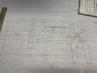
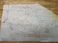
We ended up with a 3 jaw design, with similarities to an Emmert
The slide is 3ea 1-1/2" hardened ground round bars spaced 120 degrees apart.
The slide bars will be guided with linear ball bearings and bronze bushings.
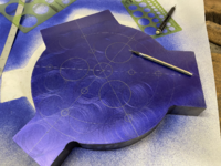
Jaw plates cut from 1-1/2" plate.
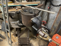
The body of the vise is a heavy turned cylinder with one end closed, that was pulled from the bone pile.
The body will be enclosed in a 10"x.500W pipe to serve as a swivel, similar to a Yost toolmakers vise.
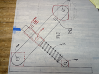
The stand will be adjustable in height and the vise will swivel in 2 directions
A few concept sketches

Royce
 

Attachments

  • tempImage8hgifK.png
    tempImage8hgifK.png
    2 MB · Views: 467
  • tempImageO3GeQK.png
    tempImageO3GeQK.png
    2.1 MB · Views: 321
  • tempImagejGdsWo.png
    tempImagejGdsWo.png
    2.2 MB · Views: 277
  • tempImageEI4jwh.png
    tempImageEI4jwh.png
    2.4 MB · Views: 287
To avoid these ads, REGISTER NOW!
OP
R

royce

Well-known member
Joined
Jun 22, 2014
Messages
3,111
Location
fairbanks ak
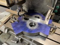
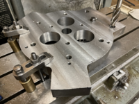
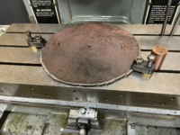
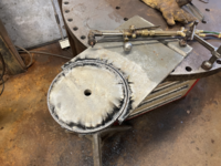
Vise body and jaw plate shaping
 

Attachments

  • tempImageGKjrfO.png
    tempImageGKjrfO.png
    3.2 MB · Views: 263
  • tempImageSPFpQi.png
    tempImageSPFpQi.png
    3.2 MB · Views: 233
  • tempImage0Fagmd.png
    tempImage0Fagmd.png
    3.1 MB · Views: 210
  • tempImage3qmyYn.png
    tempImage3qmyYn.png
    3.4 MB · Views: 224
OP
R

royce

Well-known member
Joined
Jun 22, 2014
Messages
3,111
Location
fairbanks ak
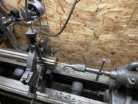
Well then,
I screwed around and beveled the wrong side of one of the jaw plates.
Then had to cut the jaw plates down a touch.
Then proceeded to face them.
 

Attachments

  • tempImage9Slh8k.png
    tempImage9Slh8k.png
    2.8 MB · Views: 216
  • tempImage8xb59l.png
    tempImage8xb59l.png
    3.8 MB · Views: 206
  • tempImageW8H7kQ.png
    tempImageW8H7kQ.png
    2.8 MB · Views: 216
OP
R

royce

Well-known member
Joined
Jun 22, 2014
Messages
3,111
Location
fairbanks ak
X-Y dimensions calc'd and plotted
Jaw plates laid out for boring and set up on the jig bore
Guide bearing bores roughed out with an annular cutter.
Tooling pins bored and reamed for 1/4" dowels.
1/2" mount bolt bores and counterbores cut.
Guide bearing bores started.
 

Attachments

  • tempImageBPqHcw.png
    tempImageBPqHcw.png
    2.6 MB · Views: 212
  • tempImage8czPvd.png
    tempImage8czPvd.png
    3.7 MB · Views: 197
  • tempImageVQIgZv.png
    tempImageVQIgZv.png
    3.1 MB · Views: 187
  • tempImage52fcQG.png
    tempImage52fcQG.png
    3.6 MB · Views: 186
  • tempImage4NLBpN.png
    tempImage4NLBpN.png
    3.6 MB · Views: 203
OP
R

royce

Well-known member
Joined
Jun 22, 2014
Messages
3,111
Location
fairbanks ak
8" cardinal jaws, 5" Starrett and 3"cardinal jaws
Also got a bunch of the running gear gathered up
 

Attachments

  • tempImageA5Reut.png
    tempImageA5Reut.png
    3.2 MB · Views: 195
  • tempImageR1WBEG.png
    tempImageR1WBEG.png
    3.2 MB · Views: 215
OP
R

royce

Well-known member
Joined
Jun 22, 2014
Messages
3,111
Location
fairbanks ak
Yes Kevin, me not so much Riv,
this machine work is all new to me, it's a lot of fun but I'm a lot more comfortable with a 3# hammer in my hand!
Kevin's knowledge, input and guidance are paramount.
 
Last edited:

KMScott

Well-known member
Joined
Feb 14, 2012
Messages
4,644
Location
Daufuskie Island, South Carolina
Royce you are doing great, how many guys would try something this complicated with no machining experience and no digital readout on a Jig Bore machine normally only used by trained special machinists in Tool Rooms across the country. I am in awe of your designing and quick learning in this dying trade. We both are having a ball with this project.
 
OP
R

royce

Well-known member
Joined
Jun 22, 2014
Messages
3,111
Location
fairbanks ak
Royce you are doing great, how many guys would try something this complicated with no machining experience and no digital readout on a Jig Bore machine normally only used by trained special machinists in Tool Rooms across the country. I am in awe of your designing and quick learning in this dying trade. We both are having a ball with this project.
Thank you kindly Kevin,
Got the 1-1/4"acme screw and nut ordered.
That has me thinking about how we might attach the meatball, what would you think about simply silver brazing it, or do you feel it needs pinned as well?
Or something all together different?

Royce
 

KMScott

Well-known member
Joined
Feb 14, 2012
Messages
4,644
Location
Daufuskie Island, South Carolina
Royce, I sure like how we did the 13” meatball with machining the two flats on each side of the round spindle and fitting it to the meatball but I used the CNC to create that shape. A little more difficult to do without a CNC and stronger when you added the 1/2” pin. .003 total clearance then silver soldering and then adding a 1/4” pin might be the way to go.
 

LXCam

ALLIANCE MEMBER
Joined
Apr 23, 2013
Messages
19,217
Location
AZ
Just getting in line to get caught up. I Dont know why since the forum change I never see your threads anymore Royce, cause I certainly enjoy them.
 

Shiftless

Well-known member
Joined
Mar 9, 2014
Messages
14,607
Location
East Bay SFO
You 2 guys are masters of design and fabrication. I’m following along to see how this one plays out. Your last joint venture monster vise was truly awe inspiring. :thumbup:
 

RoninB4

Well-known member
Joined
Jul 22, 2020
Messages
3,629
Location
Under My House
Interesting project. Did you do the milling in the last photo on the Moore? Looking forward to updates as they occur.
 
To avoid these ads, REGISTER NOW!
OP
R

royce

Well-known member
Joined
Jun 22, 2014
Messages
3,111
Location
fairbanks ak
Flopped the static plate over and counterbored for the jaw screws.

Finished tapping for the bearing cap and a couple for wooden jaws that will nest over the 8" jaws.

Rough cut the bearing bores in the vise body, with a mag drill.

Getting setup to bore for the bearings in the body.

Royce
 

Attachments

  • tempImage6OC1o0.png
    tempImage6OC1o0.png
    2.8 MB · Views: 149
  • tempImagehlcZwE.png
    tempImagehlcZwE.png
    3.7 MB · Views: 141
  • tempImagey1WQhd.png
    tempImagey1WQhd.png
    3.3 MB · Views: 140
  • tempImageH9SZxI.png
    tempImageH9SZxI.png
    2.9 MB · Views: 142

Jayman17

Well-known member
Joined
Feb 6, 2017
Messages
3,820
Location
Seattle, Wa
Royce, great to follow along on another project of yours and Kevin too. I don’t know much about machining. Is boring a hole done to take the hole to a better surface finish and a higher tolerance than say a drill bit or other type of cutter?

Jay
 
OP
R

royce

Well-known member
Joined
Jun 22, 2014
Messages
3,111
Location
fairbanks ak
Royce, great to follow along on another project of yours and Kevin too. I don’t know much about machining. Is boring a hole done to take the hole to a better surface finish and a higher tolerance than say a drill bit or other type of cutter?

Jay
Thanks Jay,
I'm no authority, but yes, more precise, in the right hands!

Royce
 
OP
R

royce

Well-known member
Joined
Jun 22, 2014
Messages
3,111
Location
fairbanks ak
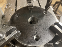
After a conference with the chief machining consultant, Kevin got me straightened out on making a simple fixture plate to get the tapped holes on the back of the vise body on line with the front.
That should finish up the machining of the vise body
 

Attachments

  • tempImageYO8yMr.png
    tempImageYO8yMr.png
    3 MB · Views: 120
  • tempImagevWx1Hd.png
    tempImagevWx1Hd.png
    2.9 MB · Views: 117
  • tempImageNxrcmV.png
    tempImageNxrcmV.png
    3.3 MB · Views: 135
OP
R

royce

Well-known member
Joined
Jun 22, 2014
Messages
3,111
Location
fairbanks ak
Finished up the bearing cap today.
I moved the the screw locations inward , so the cover could be made a bit smaller.
The cover also acts as a stock support, as it stands proud of the jaw by .250.
This will help protect the guide bars
 

Attachments

  • tempImageywuoM2.png
    tempImageywuoM2.png
    2.9 MB · Views: 123
  • tempImagelvue15.png
    tempImagelvue15.png
    2.8 MB · Views: 118
  • tempImageMT1N8L.png
    tempImageMT1N8L.png
    2.9 MB · Views: 130

LXCam

ALLIANCE MEMBER
Joined
Apr 23, 2013
Messages
19,217
Location
AZ
That’s damn impressive Royce. With all the processes what/how did you maintain indexing? Vectoring your bores once is one thing, but multiple times with flips, turns and half gainers is another :bowdown:
 

larry_g

Well-known member
Joined
Apr 28, 2007
Messages
16,900
Location
oregon
I love it, another Royce project. Somehow I missed this till today. I'm going to offer an opinion on your linear bearing choice. I spent a lot of years in automation and lots of linear bearings. The ball bearings work for low friction right up until the bearing gets a bit of grit in it and a ball skids along the shaft and ruins the shaft and bearing. When working in dirtier environments I converted the machines to a Frelon type bearing, https://www.pbclinear.com/Products/...-Bearings/FL-Inch-Closed-Linear-Plain-Bearing . They handled the loads and dirt better, if you could handle the small increase in friction. They come in standard sizes so can replace a Thompson ball bearing directly. If you haven't read the engineering on these you will find that they can me mounted in a way to allow for a bit of mis-alignment in case your machining does not get the plate bores in perfect alignment.

Good luck on your project.

lg
no neat sig line
 
OP
R

royce

Well-known member
Joined
Jun 22, 2014
Messages
3,111
Location
fairbanks ak
That’s damn impressive Royce. With all the processes what/how did you maintain indexing? Vectoring your bores once is one thing, but multiple times with flips, turns and half gainers is another :bowdown:
Thanks Cam,
I asked Kevin that very question at the beginning and he suggested drilling and reaming for dowel pins.
So, there is 3 sets of tooling pins 120 degrees apart, that were all done from one set up.

Royce
 
OP
R

royce

Well-known member
Joined
Jun 22, 2014
Messages
3,111
Location
fairbanks ak
I love it, another Royce project. Somehow I missed this till today. I'm going to offer an opinion on your linear bearing choice. I spent a lot of years in automation and lots of linear bearings. The ball bearings work for low friction right up until the bearing gets a bit of grit in it and a ball skids along the shaft and ruins the shaft and bearing. When working in dirtier environments I converted the machines to a Frelon type bearing, https://www.pbclinear.com/Products/...-Bearings/FL-Inch-Closed-Linear-Plain-Bearing . They handled the loads and dirt better, if you could handle the small increase in friction. They come in standard sizes so can replace a Thompson ball bearing directly. If you haven't read the engineering on these you will find that they can me mounted in a way to allow for a bit of mis-alignment in case your machining does not get the plate bores in perfect alignment.

Good luck on your project.

lg
no neat sig line
Thanks Larry,
Always good to hear from you.
I appreciate your experience and reference to a better product.

I ordered some secondary wipers to help keep the grit out, hoping that would help.

In this application the small amount of added friction is not an issue.
I really like the fact that the Frelon bearings are self lubricating.
Now I need to decide if the budget can handle a few hundred more dollars!

Royce
 

larry_g

Well-known member
Joined
Apr 28, 2007
Messages
16,900
Location
oregon
Thanks Larry,
Always good to hear from you.
I appreciate your experience and reference to a better product.

I ordered some secondary wipers to help keep the grit out, hoping that would help.

In this application the small amount of added friction is not an issue.
I really like the fact that the Frelon bearings are self lubricating.
Now I need to decide if the budget can handle a few hundred more dollars!

Royce
I would suggest that you keep the Frelon bearings idea in your back pocket for now. If the roller bearings work your good. If they fail in the future then know that this is an option.

lg
no neat sig line
 
OP
R

royce

Well-known member
Joined
Jun 22, 2014
Messages
3,111
Location
fairbanks ak
I would suggest that you keep the Frelon bearings idea in your back pocket for now. If the roller bearings work your good. If they fail in the future then know that this is an option.

lg
no neat sig line
Good plan
What would be a good lube for the roller bearings this application?

Royce
 
Last edited:
OP
R

royce

Well-known member
Joined
Jun 22, 2014
Messages
3,111
Location
fairbanks ak
Got started on the last of the plates today.
1" hex thrust bearing cap plate.
1"x 11" back plate for the body.
3/4"x 6" plate that ties the guide bars together and houses a pilot bearing for the spindle.
 

Attachments

  • tempImagejJqyZx.png
    tempImagejJqyZx.png
    3.4 MB · Views: 105
  • tempImagevOYJno.png
    tempImagevOYJno.png
    3.1 MB · Views: 94
  • tempImageAv7psT.png
    tempImageAv7psT.png
    3.4 MB · Views: 85
  • tempImagelVaQc2.png
    tempImagelVaQc2.png
    3.8 MB · Views: 79
  • tempImage8cDMjD.png
    tempImage8cDMjD.png
    3.1 MB · Views: 115

Lwel9226

Well-known member
Joined
Jun 7, 2014
Messages
764
Location
So Oregon
Royce.... Just found this today, good to see you back with a new project....
WOW... very impressive work, looking forward to following along..... :thumbup: :bowdown: :bowdown:

Lynn
 
OP
R

royce

Well-known member
Joined
Jun 22, 2014
Messages
3,111
Location
fairbanks ak
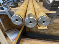
Guide bar ends drilled and tapped.
Guide bar tie plate set up for boring spindle bushing
 

Attachments

  • tempImagexTYfy2.png
    tempImagexTYfy2.png
    3.1 MB · Views: 96
  • tempImagetqgpZa.png
    tempImagetqgpZa.png
    3 MB · Views: 96
  • tempImagemxQ1t3.png
    tempImagemxQ1t3.png
    2.4 MB · Views: 104
  • tempImageDBKWjB.png
    tempImageDBKWjB.png
    3.1 MB · Views: 122
To avoid these ads, REGISTER NOW!
Top Bottom