To avoid these ads, REGISTER NOW!

Not Rocket Science...

fiftyv8

Well-known member
Joined
Dec 29, 2018
Messages
237
Location
Perth
Thru necessity I needed to lift some heavy 1" steel plate and while I worked out it was possible by improvising with vice grips, I decided to construct a gizmo to do the job more professionally lets say.

So here is what I came up with.
 

Attachments

  • IMAG0889.jpg
    IMAG0889.jpg
    73.7 KB · Views: 868
  • IMAG0890.jpg
    IMAG0890.jpg
    56.5 KB · Views: 775
  • IMAG0891.jpg
    IMAG0891.jpg
    77.8 KB · Views: 791
  • BeadRollerProject (38).jpg
    BeadRollerProject (38).jpg
    56.2 KB · Views: 791
To avoid these ads, REGISTER NOW!
OP
F

fiftyv8

Well-known member
Joined
Dec 29, 2018
Messages
237
Location
Perth
Just recently I completed a homemade powered Bead Roller from home grown scrap out of my stash.

At one point during the construction I needed a solid flat plate base for laying out and welding the main body.
I tacked the components to the thick 1inch plate to help retain their shape and integrity...

I scanned internet sites and looked at numerous pictures which eventually had my head spinning.

I made a check list of the features I thought might be useful which included, that it be;

Electric powered
Variable speed controlled
On a stand
Relatively easy to move
Have a throat of at least 24 inches
Have a die side offset adjustment
A quick release which holds existing settings
Run 1 inch shafts which step down to 7/8" for dies
An adjustable guide
Made mostly from stuff that I have in my stash
Run standard 2 inch dies
Run keyways on all shafts, even if not used

Hey, it ain't going to win any prizes but it does work and I was able to tick off all preferences set at the start of the build.
 

bullnerd

Well-known member
Joined
Sep 17, 2012
Messages
5,690
Location
Jersey
Nice job Fifty, is that threaded rod for the gripper?

Have you seen the Court Jesters vids on you tube when searching for bead roller ideas?
 
OP
F

fiftyv8

Well-known member
Joined
Dec 29, 2018
Messages
237
Location
Perth
Yep, a couple of old tensile bolts with the heads cut off, they work a treat.

Probably have seen his video, but looked at that many, I do not recall now.
I have finished mine now.

The mechanical stuff was easy enough, but I decided to use a VFD to control my motor speed and a couple of other functions which took me into uncharted electronic and programming territory which did my head in for a while until several forum cavalry members on various sites came to my rescue and all is fixed now...

There was a number of occasions in dealing with this VFD that I was ready to trash the whole idea.
I look back at it as a character building exercise...
 

bullnerd

Well-known member
Joined
Sep 17, 2012
Messages
5,690
Location
Jersey
Yep, a couple of old tensile bolts with the heads cut off, they work a treat.

Probably have seen his video, but looked at that many, I do not recall now.
I have finished mine now.

The mechanical stuff was easy enough, but I decided to use a VFD to control my motor speed and a couple of other functions which took me into uncharted electronic and programming territory which did my head in for a while until several forum cavalry members on various sites came to my rescue and all is fixed now...

There was a number of occasions in dealing with this VFD that I was ready to trash the whole idea.
I look back at it as a character building exercise...

That's cool. The Court Jester has a very simple way of making a variable speed foot pedal, mostly Why I asked.

Pics of yours when you can.
 
OP
F

fiftyv8

Well-known member
Joined
Dec 29, 2018
Messages
237
Location
Perth
If I was influenced by any single person on YouTube regarding Bead Rollers, it was probably a guy out of California named Jere Kirkpatrick who among other things was commissioned to build a bead roller for the famous Gene Winfield also in CA.

Jere it would seems had worked with the Cobra cars and Karel Shelby if I am not mistaken.
He also incorporated into his own bead roller a power take off drive, which he very skilfully demonstrated in a video where he hooked it upto another appliance he had made that was unpowered, but required power for a production run of units he was making with it.
I personally thought that was a great idea and a good use of a powered machine to power up another without going to all the trouble of adding a motor special like.

I know it ain't Rocket Science but clever all the same.

I am humbled by many of the items I see posted on here by some very skilled and dedicated people and hence question my own worthiness.

I post a pic of the bead roller soon.
 

bullnerd

Well-known member
Joined
Sep 17, 2012
Messages
5,690
Location
Jersey
I am scared... how do you know it won't fall off the grip?

lol!

Fifty-I just noticed your from down under!

Nothing but respect for you crazy buggars! :beer:

I know a few Aussies through different sites and business and am always amazed how someone can be so crazy and pure genius at the same time! :bowdown:
 
OP
F

fiftyv8

Well-known member
Joined
Dec 29, 2018
Messages
237
Location
Perth
dogdog there is no different to the Vise grips I tried and used in the first instance and they performed without incident.
The other grip method is the rotating jaw that bites more as the load increases, but way too sophisticated for what I needed.
My device will accept plate upto 1" thick which is all I need on rare occasions.

bullnerd,yes from down under and one of the most remote cities in the world they tell me.
Can't always rely on mail ordering here if you want to get the job done...

Although these days it has improved to the point where I would have to tap myself on the shoulder when struck with a problem and remind myself mail order is not my first port of call in problem solving, it is more finding a solution by working with what you have...
 

lakeroadster

Well-known member
Joined
Jan 19, 2015
Messages
5,166
Location
Central Colorado
That's just scary.. an insurance claim just waiting to happen.

"Real" plate clamps use the weight of the plate being lifted to apply mechanical force to increase the grip.

It's like any other tool, use the right one for the job at hand.

 
Last edited:
To avoid these ads, REGISTER NOW!
OP
F

fiftyv8

Well-known member
Joined
Dec 29, 2018
Messages
237
Location
Perth
I'm not selling these units or telling other people to use what I use, but for the size and weight of plate I am using it works just fine.

I used to working in the mining industry for some time and appreciated their over the top safety stuff once I had seen the quality of some of the workers that turned up on site, no doubt they were dangerous in their lack of knowledge and attitudes.

However, even privately the mine mangers at times would agree that some of their stuff was way over the top, but that always had to factor in the absolute *****.

When it came to tricky activities I had an arrangement with the chief safety officer that it would be suggested he should take a trip into town for a couple of hours so we could get the job done.

Never an accident or incident on my watch...
I would not stand under any load whether it being held by the correct tool or otherwise, but I have seen many who are willing to take that risk and have suggested that they reconsider their attitude for the sake of their loved ones...
 
OP
F

fiftyv8

Well-known member
Joined
Dec 29, 2018
Messages
237
Location
Perth
Here are a couple of pic's of the bead roller I put together from my stash junk.

I put a sheet of cardboard to make the pic's a little clearer since my shop has a lot of clutter and in the background things looked to spoil the clarity of my first pic's.

I'm happy with it and may never really use it for some time as I don't have the need right now.

I constructed as a fill in project as I needed a change and focusing on this project was a nice distraction.

It also turned a pile of scrap into something of use and value to me...

I hope you wont be too critical of it.
 

Attachments

  • IMAG1317.jpg
    IMAG1317.jpg
    70.9 KB · Views: 176
  • IMAG1316.jpg
    IMAG1316.jpg
    54.7 KB · Views: 173
  • IMAG1315.jpg
    IMAG1315.jpg
    63.3 KB · Views: 195
  • IMAG1314.jpg
    IMAG1314.jpg
    63.1 KB · Views: 202
  • IMAG1313.jpg
    IMAG1313.jpg
    68.2 KB · Views: 232

Farmall450

Well-known member
Joined
Dec 23, 2011
Messages
13,355
Location
Marengo, Illinois
I'm not selling these units or telling other people to use what I use, but for the size and weight of plate I am using it works just fine.

I used to working in the mining industry for some time and appreciated their over the top safety stuff once I had seen the quality of some of the workers that turned up on site, no doubt they were dangerous in their lack of knowledge and attitudes.

However, even privately the mine mangers at times would agree that some of their stuff was way over the top, but that always had to factor in the absolute *****.

When it came to tricky activities I had an arrangement with the chief safety officer that it would be suggested he should take a trip into town for a couple of hours so we could get the job done.

Never an accident or incident on my watch...
I would not stand under any load whether it being held by the correct tool or otherwise, but I have seen many who are willing to take that risk and have suggested that they reconsider their attitude for the sake of their loved ones...

Agreed. They don't understand just how much pressure a bolt exerts.
Also agreed I wouldn't stand under it but I wouldn't stand under anything heavy that's suspended by cable...
 
OP
F

fiftyv8

Well-known member
Joined
Dec 29, 2018
Messages
237
Location
Perth
Original motor speed of 1365rpm reduced in a gearbox by 55:1 then by chain by 3:1 and then again by chain by 3:1.
Do remember now what that comes down to but it is really nice and slow for fancy work and then the VFD speeds the motor up as required by about 3 times at full speed which is about 2000+ rpm.
 
OP
F

fiftyv8

Well-known member
Joined
Dec 29, 2018
Messages
237
Location
Perth
I built this years ago before internet and digital pic's.
I scored an old electric grinder motor from an immigrant friend who had lived in Ethiopia for most of his life and brought the grinder with him amongst his shipped goods.
It has a 1953 date stamp on it and still runs to this day.
Belt grinders had just hit the scene here but were way too costly for me at the time, so thru necessity I decided to make one from scrap.

It really is only a couple of pieces of heavy angle bolted back to back with a home made drive drum mocked up and a front nylon roller from a bearing store.

The roller and belt were the only items that cost me any money at the time...
Similarly, that is how I came to making a RED stand from junk at basically no cost.
Times were tough back then and you just had to make do with whatever you could get your hands on or make for cheap from scrap.

I scored the BLUE stand, but made the RED stand to mount my regular double ended pedestal grinder on.

Nothing fancy and definitely NOT ROCKET SCIENCE.
 

Attachments

  • IMAG1323.jpg
    IMAG1323.jpg
    72.5 KB · Views: 106
  • IMAG1324.jpg
    IMAG1324.jpg
    70.8 KB · Views: 101
  • IMAG1321.jpg
    IMAG1321.jpg
    94.1 KB · Views: 105
  • IMAG1318.jpg
    IMAG1318.jpg
    70.8 KB · Views: 106

ericlar80

Well-known member
Joined
Nov 14, 2014
Messages
362
Location
California
Original motor speed of 1365rpm reduced in a gearbox by 55:1 then by chain by 3:1 and then again by chain by 3:1.
Do remember now what that comes down to but it is really nice and slow for fancy work and then the VFD speeds the motor up as required by about 3 times at full speed which is about 2000+ rpm.

It reduces down to 2.76 rpm when the motor is at 1365 rpm. Or 4.04 rpm when the motor is at 2000 rpm.

55*3*3 = 495
1365 / 495 = 2.76 rpm

2000 / 495 = 4.04 rpm
 
OP
F

fiftyv8

Well-known member
Joined
Dec 29, 2018
Messages
237
Location
Perth
Thankyou ericlar80, that is helpful.
I did the figuring quiet a ways back when and had forgotten exactly.
I know that at 50hz it runs at 1365 rpm and the range of my VFD can take my speed down to 30hz and upto 110hz so I have the best of all worlds.

Very slow for tricky stuff and fast enough not to be bored or frustrated by too slow straight line rolling.

Funny thing is I built it kinder just for fun or because I could be so far have found no need for it.
I guess if I own it and it is ready for work, eventually I'll find a job or two for it to do.

Since I'm into hot rods and old cars I'm sure there will be a floor or firewall job that will be made easier one day...

The thing that was ROCKET SCIENCE at the beginning at least was the understanding and programming that darn VFD unit.
I'm no nerd or electronics, even computer expert and dealing fresh with that when folks a round me headed for the hills at the mention of the VFD, I was on my own for some time before I got help.

Fortunately by then I had become familiar with it and was getting a feel for what questions I could ask and understand the terms etc.

To make thing worse I purchased a unit that sounded good and seemed like it was matched well to my needs, but it turned out to be an uncommon brand and hence had little local support or knowledge from other VFD owners.

If not for more than one forum, I'd be still here scratching my head.
It sure was a character building exercise for me...
Especially having to figure out a couple of my own circuits to make my add on items work right.
 

Attachments

  • VFDconon.jpg
    VFDconon.jpg
    99.5 KB · Views: 64
OP
F

fiftyv8

Well-known member
Joined
Dec 29, 2018
Messages
237
Location
Perth
A couple of years back, during an old car build, I had the need to lift a Cadillac flathead engine with ****** attached.

Previously, I had tried a similar task using my shop crane without success.
Instead of the engine lifting up as I jacked the boom went down.

Second time around I had a less heavy ****** attached so it only weighed 720kgs.

The trouble with shop cranes is that to lift something very heavy the boom needs to be shortened right up which sometimes impedes the activity following such as trying to manoeuvre an engine into an engine bay as well as limiting the height of the lift.

The other problem with shop cranes can be that they can require quite a bit of manoeuvring space and in a confined shop with a car in it waiting for a new engine this can be tricky also.

So I decided to solve both the weight lift issue, manoeuvring space and still have a decent ability to lift a reasonable height safely, since I note that lifting engines on anything but flat ground say into an old F100 engine bay which is a high lift, is kinder risky.

So this is what I came up with;
 
OP
F

fiftyv8

Well-known member
Joined
Dec 29, 2018
Messages
237
Location
Perth
Woops, sorry about that I took a phone call during posting this and must have just hit the send button thinking I had already loaded my pic's, thanks for letting me know.

Must be getting old timers disease or something...

I post them soon.
 
OP
F

fiftyv8

Well-known member
Joined
Dec 29, 2018
Messages
237
Location
Perth
OK, down to business.
As mentioned previously, I had a need for a lifting device in my shop that could handle at least 1 ton weight and be unobtrusive due to limited space.

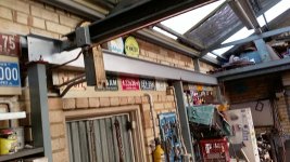
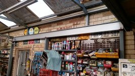
My shop has two single front rolling doors with a brick pillar in the center between the two openings, set on top of that pillar is a very heavy Universal beam that was used to support the roof at one time, but roof structure was changed to trusses and the beam became surplus to requirements, but was best left where it was.

Eventually, I levelled the beam up as it was originally sloped with the roof.
After levelling, I decided to build a kind of shelf mezzanine floor about 6 feet deep over the door openings on the inside and utilised the old beam for some central support.

Just recently, I decided I wanted to utilise that beam to help solve my lift problem.

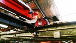
So I decided that if I replicated that front to rear beam with a similar parallel one up against the shop side wall, I could create a pair of tracks suitable for running "I" beam gantry trolleys on top of, rather than under slung like when using a chain block.

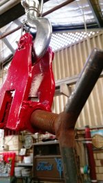
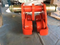
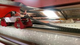
So I got hold of a 4 of those chain block girder trolleys and modified them as per the pic's and set them up to run on top of the "I" beams.

This is what I came up with...

More to follow.
 

Attachments

  • Girder Gantry (11).jpg
    Girder Gantry (11).jpg
    153.1 KB · Views: 142
  • Girder Gantry (10).jpg
    Girder Gantry (10).jpg
    162.1 KB · Views: 146
  • Girder Gantry (6).jpg
    Girder Gantry (6).jpg
    129.6 KB · Views: 139
  • Girder Gantry (3).jpg
    Girder Gantry (3).jpg
    154.9 KB · Views: 155
  • Girder Trolley01.jpg
    Girder Trolley01.jpg
    19.7 KB · Views: 37
OP
F

fiftyv8

Well-known member
Joined
Dec 29, 2018
Messages
237
Location
Perth
The next part of this project was to get a large "I" beam strung up between the two tracks and attached to the girder trolleys.

I could not have been luckier as a standard length I beam at the steel suppliers was cut into a piece for my wall track and the other for my gantry beam, I had like about 12" of waste, which I found another job for the off cut, so basically no waste.

The beam attaching points on the girder trolleys need to be clamped down but also triangular braced or gusseted back to the gantry beam to ensure both trolleys remained at 90 degrees with their track and the girder beam.

Cushion bump stops also needed to be figured out for both ends of each track beam.
 

Attachments

  • Girder Gantry (15).jpg
    Girder Gantry (15).jpg
    152.4 KB · Views: 106

Old Man Roger

Well-known member
Joined
Apr 6, 2017
Messages
17,425
Location
Palm Coast Florida
Will there be something to hold the trolley down? I could see a situation where a strap or mounting point lets go, causing any flex in the beam to act like a spring. Or if one trolley stopped moving while you were rolling a load. I may be over thinking this, I would just hate to see the beam fall on your head.
 

theoldwizard1

Well-known member
Joined
Feb 22, 2011
Messages
43,100
Location
SE MI
Good simple design !

Lifting tongs might get a better grip, but they require some initial tension.

square-hot-ingot-lifting-tong-250x250.jpg
 
OP
F

fiftyv8

Well-known member
Joined
Dec 29, 2018
Messages
237
Location
Perth
Nothing to worry about weight, gravity and good engineering are all part of this design.

I have decided to run more than just a girder trolley on my new gantry beam, I have decided to purchase an electric powered overhead winch arrangement which also offers a powered drive so the unit can drive itself along the beam from side to side.

I will still be required to move the gantry beam by hand in the other travel direction.
This unit alone will add that extra bit of weight to the beam to neutralise any bounce you maybe concerned about.

My next focus will need to be on working out a way to run safe and friendly power to a moving unit that traverses in two directions...
 
OP
F

fiftyv8

Well-known member
Joined
Dec 29, 2018
Messages
237
Location
Perth
Mounted my gantry beam spanning across to the two track trolleys and decided to try out some of that fancy plastic power cable caterpillar looking track for the cable to follow the moving beam.

So far things are starting to fall into place...:thumbup:
It sure a was a heavy manual lift getting that beam up and in place.:beer:
 

Attachments

  • Girder Gantry (17).jpg
    Girder Gantry (17).jpg
    147.4 KB · Views: 110
  • Girder Gantry (26).jpg
    Girder Gantry (26).jpg
    148.7 KB · Views: 100

Old Man Roger

Well-known member
Joined
Apr 6, 2017
Messages
17,425
Location
Palm Coast Florida
Nothing to worry about weight, gravity and good engineering are all part of this design.

I have decided to run more than just a girder trolley on my new gantry beam, I have decided to purchase an electric powered overhead winch arrangement which also offers a powered drive so the unit can drive itself along the beam from side to side.

I will still be required to move the gantry beam by hand in the other travel direction.
This unit alone will add that extra bit of weight to the beam to neutralise any bounce you maybe concerned about.

My next focus will need to be on working out a way to run safe and friendly power to a moving unit that traverses in two directions...
Just a little L shaped bracket on the outside of each trolley sure would be cheap easy insurance:) Just imagine that beam getting bumped off the track and falling:shocking:

Ok,OSHA safety rant over:lol_hitti

It's looking pretty bad ***, wish I had it.:beer:
 
OP
F

fiftyv8

Well-known member
Joined
Dec 29, 2018
Messages
237
Location
Perth
Thanks Roger, a point worth considering since it ain't difficult to do.
What I have discovered so far is the need to keep the trolleys in unison, so one does not het ahead of the other a cause some sort of racking.
They both need to remain at 90 degrees to the track as well as the gantry beam at all times.

Here is a pic of my cheap *** bump stop, of which I need 4, being one at each end of both tracks.

I also needed to add to the end of one track some steel angle bolted to the center web of one of the tracks to ensure there was no possibility that a trolley could over run the end of the track and fall.
Only one scenario for that as the other 3 track ends terminate against very solid other members should the bump stop fail.

Next step is to install my winch and get power similar to my previous pic's for the tracks, but to the gantry beam now.

Sorry if any of my pic quality is a bit off, I had glare and sometimes darkness issues which I have tried to improve with my auto correct function...
 

Attachments

  • Girder Gantry (38).jpg
    Girder Gantry (38).jpg
    107.4 KB · Views: 93
To avoid these ads, REGISTER NOW!
Top Bottom