To avoid these ads, REGISTER NOW!

Old 4 Post Hoist Wiring

Neura

Well-known member
Joined
Feb 23, 2009
Messages
79
Location
St. Albert, Alberta, CAN
So I got an old 4 post hoist, and I am fixing it up, but the contactor and the remote switch were missing, I have a spare contactor from my compressor that I didnt need, and I picked up a box and a single push button switch today for the switch now I just need to wire everything up, just not clear on how everything needs to be wired... this is my first time with Hydraulics, and electric and a electric solenoid for the hydraulics.

Anyone know how this should be wired up??

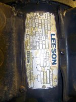
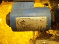
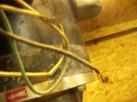
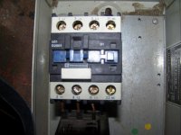
First pic is of the pump and motor attached to the post, second is the motor wires (green, black, white). third is the motor, 4th should be the solenoid for the pump. 5th pic should be the wires for the solenoid (green, black, white) smaller gauge then the motor. the last 2 are the contactor and the relay for the contactor. I haven't looked at the contactor in at least 2 years now and forget how they get wired. I know the relay goes into T1,T2,T3. and L1,L2,L3 are for the power wires from the panel. Also since this is a 220V 1 Ph I will only be using L1 and L3 and T1 and T3. what I really can't remember is how the switch would go into the relay to activate the solenoid and the solenoid attaches to?? The contactor also has A1, A2, A3. and the relay has NO1, NO2, NC1, NC2 on it as well...

oh the solenoid for the hydraulics actually says 220V 60HZ on it as well.
 

Attachments

  • 100_2914.jpg
    100_2914.jpg
    146.3 KB · Views: 10
  • 100_2915.jpg
    100_2915.jpg
    136.6 KB · Views: 7
  • 100_2917.jpg
    100_2917.jpg
    142.3 KB · Views: 10
  • 100_2921.jpg
    100_2921.jpg
    134.1 KB · Views: 7
  • 100_2929.jpg
    100_2929.jpg
    134.1 KB · Views: 8
  • 100_2933.jpg
    100_2933.jpg
    140.7 KB · Views: 8
  • 100_2934.jpg
    100_2934.jpg
    143.5 KB · Views: 8
To avoid these ads, REGISTER NOW!

fefarms

Well-known member
Joined
Jan 25, 2007
Messages
186
The box marked LM2 D13 is an electronic overload detector. You would need to set the dial to match the 15.3 FLA on the motor nameplate. Some of these have "loss of phase" detection and will false-trip if you try to use it on a single phase motor.

You need to figure out the hydraulics. My guess is that the solenoid valve is normally closed, the solenoid controlling it is not energized. When the motor is powered, fluid is pumped into the cylinder, the ram extended, and the lift is raised. When the motor stops, the closed valve holds the fluid trapped in the cylinder, and the lift stays up. To lower the lift, energize the solenoid, which opens the valve and allows the fluid to return to the tank.

So you need two normally open push buttons. (One for up and one for down). Wire the up button in series with the overload detector and also the contactor coil. (You need to figure out the coil voltage; the appropriate voltage is applied to the other side of the button and the other side of the contactor coil._ L1 and L3 go to 240 volts. T1 and T3 pass through the overload detector and connect to black and white on the motor.

The other button (down) connects to L1 on one side, and the solenoid on the other. The other side of the solenoid goes to L3.

But all this is predicated on my guess as to the hydraulic piping.
 
OP
N

Neura

Well-known member
Joined
Feb 23, 2009
Messages
79
Location
St. Albert, Alberta, CAN
So I stopped by the hydraulic shop today and he pretty much explained how everything works... he wasnt sure about the contactor setup though and he said by the motor size I wouldnt need a contactor for it, just 2 push buttons to interrupt the hot wires basically making them switched. the motor has an auto reset overload protection on it... so maybe I shouldn't worry about the contactor?? According to the hoist guys I have been talking with these originally came with a contactor and a 2 push button switches, he has a switch he could sell me, but no contactor... I figured I would just build my own switches for this though... so now I guess what would be the best way to wire it up...


If I go with the contactor does anything need to be hooked up to A1, A2, A3?? or to the 2 NO, or the 2 NC terminals? I seem to remember there was a Jumper wire once upon a time when this was used when this was hooked up on the original compressor motor, but I dont remember now how that was hooked up. I think it went from A2 to NC2 last time...
 
To avoid these ads, REGISTER NOW!

fefarms

Well-known member
Joined
Jan 25, 2007
Messages
186
15 amps is a lot to switch with a push-button. I'd use a contactor.
(That said, my Bear 8000 two post lift came from the factory with a 20 amp limit switch to control the motor -- and no contactor).

A1 and A2 on a contactor are normally the connections for the actuating coil. You apply one side of the appropriate voltage to A1, A2 connects to one terminal on the switch, and the other terminal of the switch goes to the other side fo the control voltage.

If the motor has built in overload protection you do not need the electronic overload detector, nor its NC/NO contacts.

The contactor has a pair of NC contacts to use as auxilliary control. You shouldn't need to use these for your application.
 
OP
N

Neura

Well-known member
Joined
Feb 23, 2009
Messages
79
Location
St. Albert, Alberta, CAN
Thanks for all the help I think I have it all figured out now, the coil is a 120V so I need to pull a Neutral from the panel to A1 on the coil.
 
OP
N

Neura

Well-known member
Joined
Feb 23, 2009
Messages
79
Location
St. Albert, Alberta, CAN
thought of another question actually, we have been trying to figure out a way to add a limit switch to the hoist as well because different cars, trucks, vans go on the lift and we have a 10' ceiling right now and I know someday it will happen that someone isnt watching the height.... I am thinking of maybe the garage door safety sensors and wired in series to the motor so if the beam is broken it wouldnt allow it to go up any further... issues with that of course is I need to raise it a smidge to release the locks to let it down... so maybe an override switch somewhere for the sensors as well... havent really looked into what is available yet for limit switch functions.. so any ideas would be helpful.
 
To avoid these ads, REGISTER NOW!
Top Bottom