To avoid these ads, REGISTER NOW!

One year later 40'x80'

OP
F

fnieto

Well-known member
Joined
Aug 27, 2013
Messages
1,401
Location
Tucson,Arizona
I also used a magnetic base test indicator to verify the carriage, cross feed, compound and tailstock dials and movement.
The carriage movement was spot on.1 TIC MARK =.010"
attachment.php

attachment.php

Next was the compound. 1 TIC MARK= .001"
attachment.php

Spot on as well.
attachment.php

The cross feed. 1 TICK MARK= .0005" (.010"= .005")
attachment.php

Exactly 1/2 of what dial reads. So far so good.
attachment.php


Very pleased with these results. The tailstock is next.
 

Attachments

  • IMG_2889.jpg
    IMG_2889.jpg
    131.2 KB · Views: 1,210
  • IMG_2890.jpg
    IMG_2890.jpg
    128.4 KB · Views: 1,214
  • IMG_2891.jpg
    IMG_2891.jpg
    126.2 KB · Views: 1,204
  • IMG_2895.jpg
    IMG_2895.jpg
    129.6 KB · Views: 1,202
  • IMG_2899.jpg
    IMG_2899.jpg
    130.7 KB · Views: 1,193
  • IMG_2903.jpg
    IMG_2903.jpg
    129.6 KB · Views: 1,200
Last edited:
To avoid these ads, REGISTER NOW!
OP
F

fnieto

Well-known member
Joined
Aug 27, 2013
Messages
1,401
Location
Tucson,Arizona
The tailstock movement verification setup. I also double checked the compound since the setup allowed for this.
attachment.php


Tailstock dial, 1TIC MARK=.001"
attachment.php

Pretty damn good fora tailstock.
attachment.php

Double checked the compound, results where the same as first setup. G-to-G.
attachment.php

attachment.php


The DRO arrived yesterday at some point while I was out in the shop. Found it outside after dark sitting by the front door. EL700 3-axsis LCD touch screen.
attachment.php

Will install this tomorrow and taper attachment while the splashguard is removed.
More to come later.
Thanks for the visit.
Paco
 

Attachments

  • IMG_2907.jpg
    IMG_2907.jpg
    130.2 KB · Views: 1,192
  • IMG_2906.jpg
    IMG_2906.jpg
    124.3 KB · Views: 1,198
  • IMG_2905.jpg
    IMG_2905.jpg
    124.7 KB · Views: 1,188
  • IMG_2908.jpg
    IMG_2908.jpg
    126.7 KB · Views: 1,195
  • IMG_2909.jpg
    IMG_2909.jpg
    120.2 KB · Views: 1,192
  • IMG_2912.jpg
    IMG_2912.jpg
    140.2 KB · Views: 1,191
OP
F

fnieto

Well-known member
Joined
Aug 27, 2013
Messages
1,401
Location
Tucson,Arizona
Awesome Paco. I'll bet your excited to get her up and running.

Looks like a nice quality machine.

Hey Mike,
Yeah, chomping at the bit man. Milled a mounting bracket for the DRO head unit, need to make one last cut drill and tap some holes. then onto the magnetic scales.

Have a great weekend amigo.

Paco
 
OP
F

fnieto

Well-known member
Joined
Aug 27, 2013
Messages
1,401
Location
Tucson,Arizona
Picked up a 52" low profile LED strip light for the backsplash.
Its held in with snap in magnet clips and tucks up under the top return going unnoticed when off. Puts out hella light with the right temp.
attachment.php

attachment.php

attachment.php

Overhead lights off in the shop.
attachment.php


More to come later.
Paco
 

Attachments

  • IMG_2923.jpg
    IMG_2923.jpg
    134.4 KB · Views: 1,134
  • IMG_2921.jpg
    IMG_2921.jpg
    134.4 KB · Views: 1,117
  • IMG_2920.jpg
    IMG_2920.jpg
    145.1 KB · Views: 1,123
  • IMG_2919.jpg
    IMG_2919.jpg
    132.8 KB · Views: 1,128

LXCam

ALLIANCE MEMBER
Joined
Apr 23, 2013
Messages
19,093
Location
AZ
That's a seriously nice piece of equipment paco, very impressive my friend. I have an acra hydraulic press I absolutely luv and my lathe is a duplicate to the 13/40 on their website. Until seeing how your dials were set up for SAE / metric readings it never occurred to me to see if mine is the same deal. Now I'm chomping st the bit to find out, that's gonna be the second thing I do in the morning now...lol
 

cajunrebel`

Well-known member
Joined
Sep 5, 2015
Messages
70
Yeah, I thought I'm met my match on that one. It is amazing the force those bolts can take. We had large wing bolts (spline heads and nuts) on F-16's that connected the finger brace to the fuselage that required a 6' torque wrench and two guys to torque.
I see you've been around F-16's a bit. Where did you have the pleasure of working on them? Also, what AFSC were you? I spent 8 years on them as a crew chief. Nellis, Kunsan, and Eglin. Mostly test and eval work. I changed 3 wings at Nellis and know how fun it is cleaning away the B 1/2 from those fuselage attach bolts for the finger braces. We did a torque check once on the fleet and I remember seeing a 3/8" drive spline socket split in half violently before it got to torque for the finger braces to wing bolts.

Sent from my E6810 using Tapatalk

Nevermind my original questions. I read futher back and saw you were fuels. I was wondering how you managed to learn as much machining and also got your hands into the wing root areas. Not many guys get as much skilled training as you have had. I would love to cross train to fabrication flight, but it's not in the cards for me to go back off to tech school right now.
 
Last edited:
OP
F

fnieto

Well-known member
Joined
Aug 27, 2013
Messages
1,401
Location
Tucson,Arizona
That's a seriously nice piece of equipment paco, very impressive my friend. I have an acra hydraulic press I absolutely luv and my lathe is a duplicate to the 13/40 on their website. Until seeing how your dials were set up for SAE / metric readings it never occurred to me to see if mine is the same deal. Now I'm chomping st the bit to find out, that's gonna be the second thing I do in the morning now...lol

Morning Cam,
If you only have a viewing window showing decimal graduations on your cross feed chances are pretty darn good you have a rotating collar. There should be a detent ball visible from the top view and to the left. Give it a squirt with WD and work it in/out with a small blunt tip tool. It resembles a chrome ball oiler.
They usually only rotate 180º so don't crank too much in the wrong direction.
attachment.php


Enjoy your weekend brother.

Paco
 

Attachments

  • IMG_2777.jpg
    IMG_2777.jpg
    135.9 KB · Views: 1,107
OP
F

fnieto

Well-known member
Joined
Aug 27, 2013
Messages
1,401
Location
Tucson,Arizona
I see you've been around F-16's a bit. Where did you have the pleasure of working on them? Also, what AFSC were you? I spent 8 years on them as a crew chief. Nellis, Kunsan, and Eglin. Mostly test and eval work. I changed 3 wings at Nellis and know how fun it is cleaning away the B 1/2 from those fuselage attach bolts for the finger braces. We did a torque check once on the fleet and I remember seeing a 3/8" drive spline socket split in half violently before it got to torque for the finger braces to wing bolts.

Sent from my E6810 using Tapatalk

Nevermind my original questions. I read futher back and saw you were fuels. I was wondering how you managed to learn as much machining and also got your hands into the wing root areas. Not many guys get as much skilled training as you have had. I would love to cross train to fabrication flight, but it's not in the cards for me to go back off to tech school right now.

First off, Thank you for your service brother.
I was fortunate enough to be stationed at 162nd fighter wing here in Tucson. Employed full time as a WG-10 and active reserves status. All the same training as active duty and wore the uniform everyday. When you say "fuels", I was a fuel systems Technician AFSC 2A674 not POL. We used the POL guys to re-fuel/refuel during troubleshooting fuel imbalance issues and such. I also had to work in the "tank farm" (wing tanks/centerline tanks) as well as servicing Hydrazine (H-70) tanks. Working as a civil service employee during the week (still in uniform and with rank) we had the flexibility to design and make a lot of specialty tooling enhancing many different aspects of different tasks. I invented several jigs and tooling while working requiring time at the machine/welding shop. I worked as a machinist in HS and took a lot of shop classes as a youngster. The rest has been learned on my own using he fundamentals from the sum of all experiences. I call it common sense shop work really. The other benefit of modern-day living is the internet. A person can find out anything they want to learn by searching at any hour of the day. This has been so beneficial and is why I like to share as much online with tons of photos for others to possibly benefit. Unfortunately, many hacks now post and can also be watched on reality shows so pick your poison carefully.


I never saw a crew chief scrape sealant haha, yeah, that **** was a PITA but I've used it on personal projects (expired date and was headed for the garbage). Best sealant I've ever used.
Later,
Paco

Paco
 

Finallygotit

ALLIANCE MEMBER
Joined
Jul 6, 2013
Messages
4,078
Location
Tucson, AZ
Paco,

If you don't mind me asking, where did you get that LED strip light? If they make something smaller I have a couple of ideas for my machines.

Thanks!

:beer:
 

LXCam

ALLIANCE MEMBER
Joined
Apr 23, 2013
Messages
19,093
Location
AZ
Good afternoon Paco, welp I checked my lathe and as luck would have it, I didn't have such badassesness of that particular built in feature. But fortunately all my dials are marked in thou's so my pea brain isn't required to do much thunking......that's a good thing :lol:


Have fun with that beauty and with how well you take care of your equipment she'll last your lifetime easy.
 
OP
F

fnieto

Well-known member
Joined
Aug 27, 2013
Messages
1,401
Location
Tucson,Arizona
Paco,

If you don't mind me asking, where did you get that LED strip light? If they make something smaller I have a couple of ideas for my machines.

Thanks!

:beer:

Here's a link where I got the LED strip. He offers different lengths. I didn't need the power supply. Also make sure you tell him you need a lens if you use it on a machine. He offers both clear and frosted lenses that snap on the aluminum track.https://www.ebay.com/itm/Super-Brig...var=481315932862&_trksid=p2057872.m2749.l2649

Paco
 
OP
F

fnieto

Well-known member
Joined
Aug 27, 2013
Messages
1,401
Location
Tucson,Arizona
Good afternoon Paco, welp I checked my lathe and as luck would have it, I didn't have such badassesness of that particular built in feature. But fortunately all my dials are marked in thou's so my pea brain isn't required to do much thunking......that's a good thing :lol:


Have fun with that beauty and with how well you take care of your equipment she'll last your lifetime easy.

Thanks Cam,
FYI, I convert to decimal when I machine metric. I share the same brain hahah.
You won't miss the dial.
 

Finallygotit

ALLIANCE MEMBER
Joined
Jul 6, 2013
Messages
4,078
Location
Tucson, AZ
OP
F

fnieto

Well-known member
Joined
Aug 27, 2013
Messages
1,401
Location
Tucson,Arizona
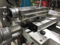
Yesterday we worked on the modifications from dawn to well after dark. I began with placing the machine on the floor. The heave pallet made it difficult to take accurate measurements with the machine 8" higher and I'm not tall. I had to make a custom mount/arm for the DRO as the kit's display head was not square and was driving me nuts. The rest of the DRO is super nice quality but the brackets, well they sucked. My Friend Mark arrived after 9 am and brought along the entire new control system and front upgraded switches. I had provided him with an aluminum sheet cut to fit the electrical panel last week. This allowed him to fully assemble the components and bench test prior to install. He had the upgraded panel in place in no time and ran upgraded shielded cabling. The front switch panel got fancy new switches and cabling as well. His work is impeccable and super detailed. His color coded schematics are equally impressive and the easiest to follow.

Befor:
attachment.php


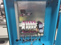
After: The reason it looks lacking of components is because this is a 12/24 vdc system and the rest of the goodies are mounted on a wall enclosure where the lathe will be set. The wall enclosure houses the VFD, brake resistor, power supply, fuses, power disconnect and cooling fans.
attachment.php


The upgraded front switches. The far right Joy stick will jog fwd/rvs programed to 20htz on VFD allowing to power tap and general jogging. E-stop will utilize motor braking (1.2 or so) seconds via VFD. The green push button is dual role. when lit is indicates power (pilot light) and when pushed it bi-passes the carriage micro stop proximity sensor. The blue (lit) switch is two stage flood control, off, constant flooding and flooding when spindle/motor is running.
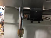
The last far left micro toggle is two stage motor braking. up (position 1) will provide motor braking like the E-stop just over a second. Position 2 (awn) will brake in 3-5 seconds and controlled by programming the VFD. The foot brake also triggers the same braking as E-stop but will mostly be used for large manual tapping.

attachment.php


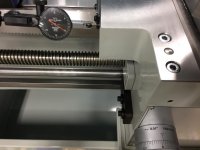
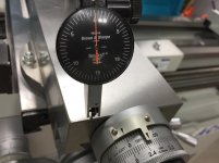
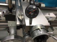
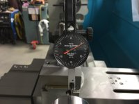
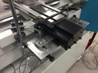
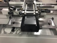
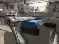
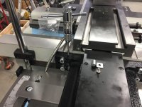
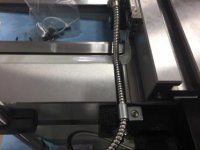
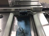
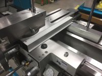
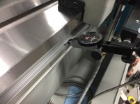
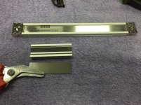
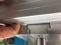
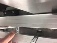
Mark modified the micro carriage stop to fit a proximity sensor and a back up two stage micro switch in case of proximity failure. The proximity kicks in at 3mm air gap and the dial turns silky smooth. I will make some thumb screw to eliminate the need for an Allen. I also need to make a trigger plate that will be installed on the leading carriage. I really like how he profiled the stop to follow the V-ways angle. The trigger stop profile will match his work.
This feature allows for blind boring, boring to a shoulder, blind threading or any other application requiring repeatability without crashing or over cutting. I have the same on the 1440 and luv it.
attachment.php


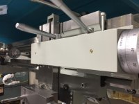
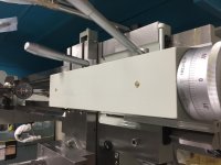
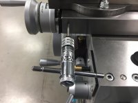
Mark also built a custom Tack/sfpm and modified the voltage required to operate with the new control system. Every component was soldered by him and he also milled the box to fit a lexan window flush to the outside. The box also had the speed control pot.
attachment.php

Close up of front. Notice the cover is to the rear for a clean face.
attachment.php


We also installed an hour meter to assist in maintenance service intervals.It will only record motor run time and idle when machine is powered up. I run hour meters on the compressor and plate roller never over/under servicing the machines. I still need one on the iron worker
attachment.php


More to come as I'm at the photos limit.
Paco
 

Attachments

  • IMG_2770.jpg
    IMG_2770.jpg
    135.1 KB · Views: 1,025
  • IMG_2935.jpg
    IMG_2935.jpg
    139.2 KB · Views: 1,027
  • IMG_2938.jpg
    IMG_2938.jpg
    140.3 KB · Views: 1,017
  • 20180130_171328.jpg
    20180130_171328.jpg
    145.8 KB · Views: 1,015
  • IMG_2940.jpg
    IMG_2940.jpg
    142.7 KB · Views: 1,012
  • IMG_2933.jpg
    IMG_2933.jpg
    126 KB · Views: 1,010
  • IMG_2934.jpg
    IMG_2934.jpg
    127.5 KB · Views: 1,016
OP
F

fnieto

Well-known member
Joined
Aug 27, 2013
Messages
1,401
Location
Tucson,Arizona
The last thing we did was remove the backsplash and installed the heavy taper attachment.
The instructions indicate 1 hour but we managed to get it in about 40-45 minutes. The adjustments have to be exact or the cross feed lead screw will not turn smoothly throughout the travel. I also need the backsplash removed to install the long magnetic scale.
attachment.php

Here you can see the quick clamp mocking up the thin mag scale for the cross feed.
attachment.php


The DRO and Tachometer/speed control box
attachment.php


The naked machine as its sits on the floor.
attachment.php


Thanks for viewing.

Paco
 

Attachments

  • IMG_2936.jpg
    IMG_2936.jpg
    133.3 KB · Views: 995
  • IMG_2937.jpg
    IMG_2937.jpg
    132.9 KB · Views: 1,000
  • IMG_2939.jpg
    IMG_2939.jpg
    143.1 KB · Views: 1,004
  • IMG_2941.jpg
    IMG_2941.jpg
    136.6 KB · Views: 1,006
To avoid these ads, REGISTER NOW!

LXCam

ALLIANCE MEMBER
Joined
Apr 23, 2013
Messages
19,093
Location
AZ
Holy smoly Paco, it looks like your next step is a cnc controller and call it a day :p

The lathe was already impressive in its self, now it's just flat out badass. It does get very tiring / stressful boring blind holes manually, that set up is very slick.
 
OP
F

fnieto

Well-known member
Joined
Aug 27, 2013
Messages
1,401
Location
Tucson,Arizona
Holy smoly Paco, it looks like your next step is a cnc controller and call it a day :p

The lathe was already impressive in its self, now it's just flat out badass. It does get very tiring / stressful boring blind holes manually, that set up is very slick.

Thanks Cam. I new makeover makes it sort of a smart lathe without a computer.
Threading or boring a blind hole without a proximity stop just takes too long. The third axis scale on the compound will come in hand for final dimensions.

Take it easy Cam and have a great week.
Paco
 
OP
F

fnieto

Well-known member
Joined
Aug 27, 2013
Messages
1,401
Location
Tucson,Arizona
only got a few hours in the shop today. I had to play Mr. Maytag after walking the hounds.
Trouble shot a code (PE) the washing machine was throwing. Took the two water solenoid valves out and cleaned the sand rubies occluding the strainers. The wife is back in the game.
Anyway, on to some real fun.

I got the X axis scale (cross feed) mounted and working. The brackets supplied required custom milling to fit my liking. drilled and tapped seven holes. Broke one tap (1/4-20) on the Meehanite casting. I must be living right, cuz it broke leaving enough to grab with a mini needlenose vice grip. Man I was bummed when it snapped, but realized how lucky I got.
The tailstock was removed and the carriage was moved as far back as possible. Drilling was done with a cordless drill and tapping required a 3/8" drive extension and ratchet.

The reader head bolts where drilled 3/4" deep for a good hold. I used SAE SS hardware. I don't care for the metric hardware supplied with the kit.
attachment.php


The lathe came machined for the use of scales and saved me time as mounting surfaces where flat and true. Tapping was done using two 2x4 blocks (stacked). This provided the correct hight to keep things lined up.
attachment.php


attachment.php


The scales where drilled/tapped for 8-32 SS button head Allen screws. The magnetic scales can be cut to size unlike glass scales. They are low profile keeping things tight.
attachment.php


Once mounted, the reader head is adjusted using four jack screws to achieve the required .020" air gap. A plastic shim is included to assist.
attachment.php


attachment.php
 

Attachments

  • IMG_2943.jpg
    IMG_2943.jpg
    127.3 KB · Views: 1,262
  • IMG_2944.jpg
    IMG_2944.jpg
    130.1 KB · Views: 1,262
  • IMG_2945.jpg
    IMG_2945.jpg
    123.8 KB · Views: 1,260
  • IMG_2946.jpg
    IMG_2946.jpg
    127.8 KB · Views: 1,252
  • IMG_2949.jpg
    IMG_2949.jpg
    131.2 KB · Views: 1,254
  • IMG_2950.jpg
    IMG_2950.jpg
    117.6 KB · Views: 1,253
Last edited:
OP
F

fnieto

Well-known member
Joined
Aug 27, 2013
Messages
1,401
Location
Tucson,Arizona
The reader head cable was secured using supplied clamp. The carriage is grooved to nest the shielded cable (very nice touch). The taper attachment was drilled and tapped 8-32 to secure the said clamp.
The scale cover was drilled and mounted to the scale ends. These too where drilled and re-tapped to 8-32 keeping all hardware matching.

attachment.php


attachment.php

The machined groove really helps securing the cable.
attachment.php


Some shots of the finished X scale install.
attachment.php


attachment.php


attachment.php


Tested the instal and all was good. I really like the DRO LCD display. The touch screen is slick too.
attachment.php


Back on shift tomorrow so progress will slow down as I work 24 hour shifts. More on Tuesday.
Thanks for stopping by.

Turn and Burn,
Paco
 

Attachments

  • IMG_2953.jpg
    IMG_2953.jpg
    139.5 KB · Views: 1,240
  • fullsizeoutput_660.jpg
    fullsizeoutput_660.jpg
    13.7 KB · Views: 1,238
  • IMG_2956.jpg
    IMG_2956.jpg
    127.1 KB · Views: 1,243
  • IMG_2958.jpg
    IMG_2958.jpg
    132.3 KB · Views: 1,244
  • IMG_2959.jpg
    IMG_2959.jpg
    131.9 KB · Views: 1,232
  • IMG_2961.jpg
    IMG_2961.jpg
    137.3 KB · Views: 1,239
  • IMG_2960.jpg
    IMG_2960.jpg
    132.6 KB · Views: 1,242

cajunrebel`

Well-known member
Joined
Sep 5, 2015
Messages
70
First off, Thank you for your service brother.
I was fortunate enough to be stationed at 162nd fighter wing here in Tucson. Employed full time as a WG-10 and active reserves status. All the same training as active duty and wore the uniform everyday. When you say "fuels", I was a fuel systems Technician AFSC 2A674 not POL. We used the POL guys to re-fuel/refuel during troubleshooting fuel imbalance issues and such. I also had to work in the "tank farm" (wing tanks/centerline tanks) as well as servicing Hydrazine (H-70) tanks. Working as a civil service employee during the week (still in uniform and with rank) we had the flexibility to design and make a lot of specialty tooling enhancing many different aspects of different tasks.

I never saw a crew chief scrape sealant haha, yeah, that **** was a PITA but I've used it on personal projects (expired date and was headed for the garbage). Best sealant I've ever used.
Later,
Paco

Paco

You and I were referring to the same AFSC. I was a 2A373. I'm going back in to work for the Louisiana ANG in Belle Chase soon under the same ASFC, but I'll be working on F-15's. I am going to be working as a federal technician as well.
At Nellis and Eglin back shop jobs are performed by civilians and they are very short staffed. We helped out where we could. I have to forklift my aircrafts wing (had corrosion internally around the fitting where the wing tank mounting stud passes through) to the fuel barn from supply and even had to help remove the old wing. It was a great learning experience as a SrA.
Anyways thank you also for your service and I'll quit jumbling up your thread now.

Sent from my E6810 using Tapatalk
 
OP
F

fnieto

Well-known member
Joined
Aug 27, 2013
Messages
1,401
Location
Tucson,Arizona
You and I were referring to the same AFSC. I was a 2A373. I'm going back in to work for the Louisiana ANG in Belle Chase soon under the same ASFC, but I'll be working on F-15's. I am going to be working as a federal technician as well.
At Nellis and Eglin back shop jobs are performed by civilians and they are very short staffed. We helped out where we could. I have to forklift my aircrafts wing (had corrosion internally around the fitting where the wing tank mounting stud passes through) to the fuel barn from supply and even had to help remove the old wing. It was a great learning experience as a SrA.
Anyways thank you also for your service and I'll quit jumbling up your thread now.

Sent from my E6810 using Tapatalk

Congrats, on the civil service gig.
I fist worked on A-7 Vought Corsair II for several years before the VN era birds wings developed cracks. We used up all the wings DEPOT had and eventually converted over to the Falcons.
The wings where flown in by a Guppy, What a odd looking aircraft that was. The A-7 where a nightmare to work on with button and laced in fuel bladders.

Jump in anytime man, Thats why I keep this in "The Gallery" and not a specific thread.
Always good to chat about jobs. Jobs are what make us into well rounded craftsmen.

Take care,
Paco
 

zmotorsports

ALLIANCE MEMBER
Joined
Oct 20, 2009
Messages
21,347
Location
Northern Utah
Nice Paco. I keep telling myself one of these days when I have some spare $$$ I'm going to add a DRO to my lathe. Just haven't ran across that day yet.:lol:
 
OP
F

fnieto

Well-known member
Joined
Aug 27, 2013
Messages
1,401
Location
Tucson,Arizona
Nice Paco. I keep telling myself one of these days when I have some spare $$$ I'm going to add a DRO to my lathe. Just haven't ran across that day yet.:lol:

Hey Mike,

I ran my 1440 for seven years before adding a DRO. Remember that that overwhelming feeling you got when you added the 5C scroll chuck? Well its the same deal. It speeds things up and prevents errors during over zealous cuts. The DRO I just added has cool features like Zero Approach,Job timer, Shrinkage factor (no not that shrinkage) Vectoring and Summing among other standard features. Bottom line, your eyes will thank you.

Oh, did you notice the new tap wrench? my neighbor is a Matco dealer and sold me the little brother to the Snappy you, Mac and I own. Its identical (only smaller) in all aspects but it's made in China. His cost $33. I gave him two Andrew Jacksons.

Get a DRO and thank me later but don't curse me during the install ; )

Paco
 
Last edited:

zmotorsports

ALLIANCE MEMBER
Joined
Oct 20, 2009
Messages
21,347
Location
Northern Utah
Hey Mike,

I ran my 1440 for seven years before adding a DRO. Remember that that overwhelming feeling you got when you added the 5C scroll chuck? Well its the same deal. It speeds things up and prevents errors during over zealous cuts. The DRO I just added has cool features like Zero Approach,Job timer, Shrinkage factor (no not that shrinkage) Vectoring and Summing among other standard features. Bottom line, your eyes will thank you.

Oh, did you notice the new tap wrench? my neighbor is a Matco dealer and sold me the little brother to the Snappy you, Mac and I own. Its identical (only smaller) in all aspects but it's made in China. His cost $33. I gave him two Andrew Jacksons.

Get a DRO and thank me later but don't curse me during the install ; )

Paco

I did notice the smaller tap handle and was going to comment on it. I also noticed it said Matco on it. I did't realize they carry them as I bought mine from Snap On many moons ago. I have had a couple people ask me about mine so I will have to direct them to a Matco truck near them.

One of these days I am sure I will get a DRO setup but after building the shop this past year, painting the coach, reupholstering the coach and now purchasing a new PSC steering box for the Jeep getting her ready for off-roading this summer, I may have to wait a bit and let my savings recover a bit.:D

I'll just have to live vicariously through you for a while my friend.
 
OP
F

fnieto

Well-known member
Joined
Aug 27, 2013
Messages
1,401
Location
Tucson,Arizona
Yesterday, I got the Y/Z axis installed. The 5 micron magnetic scale is 46" long end to end. I used two sided 3M tape to hold it in place for mock up and hole transfer punch. The machined has a large machined flat surface for scale mounting. I was able to direct mount the scale without the use of secondary brackets.

Laid-out the scale and measured the end to end carriage travel and stuck the scale on with the 3M trick. Working alone, this worked very well, so well that I used dental floss to cut the two sided tape to remove the scale for drilling. The profile of the magnetic scale is compact with only protruding .375". The long scale kit came with two center support mounts that index into the center groove of the extruded aluminum housing. I only needed the bottom to correct the .0015" sag. The center top clamp was not needed since the scale remained flat against the machine surface. The use of the top clamp would also hinder the cover/shield from sitting flat on the top of the scale.

A target reference line was transferred onto the lathe after end to end travel of the carriage.
The goal is to use all the traverse travel without crashing the read head into the end brackets of the scale.

attachment.php


The scale is secured using the 3M double side tape.

attachment.php


The read head bracket was mocked up and end to end travel double checked prior to drilling and tapping.

attachment.php


Transfer punched keeping the punch at the bottom of the slot for maximum downward adjustment. I did this to allow clearance for the cover shield.

attachment.php


Removed the scale drilled/tapped for the end mounts (8-32). Once mounted with two SS button head allen screws the top of the scale was swept and adjusted for parallelism. The middle (22.5") had a slight sag if .0015" and a single center clamp was drilled/tapped. The test indicator assisted in brining the center true.

attachment.php


The test indicator was then setup for verifying the face or flatness. The end mounts have five grub screws to adjust if necessary. The machine surface yielded only .0015 variance (probably paint), well below the tolerances indicated for a 46" scale.

attachment.php


attachment.php


More to follow....
 

Attachments

  • IMG_2965.jpg
    IMG_2965.jpg
    128.2 KB · Views: 1,129
  • IMG_2966.jpg
    IMG_2966.jpg
    128.3 KB · Views: 1,125
  • IMG_2967.jpg
    IMG_2967.jpg
    130.5 KB · Views: 1,125
  • IMG_2968.jpg
    IMG_2968.jpg
    123.7 KB · Views: 1,129
  • IMG_2973.jpg
    IMG_2973.jpg
    128.3 KB · Views: 1,132
  • IMG_2971.jpg
    IMG_2971.jpg
    128.3 KB · Views: 1,127
  • IMG_2972.jpg
    IMG_2972.jpg
    127.1 KB · Views: 1,129
OP
F

fnieto

Well-known member
Joined
Aug 27, 2013
Messages
1,401
Location
Tucson,Arizona
Once the scale was installed the read head bracket was cut and drilled. The drilled holes where slotted .100" up and .200" downward. Before any slotting was done, the holes where used to transfer punch the hole locations on the rear of the carriage, drilled/tapped two 1/4-20.

Here the reader bracket is snugged and reader head gap set (.020") using the supplied shim.
Here you can also see the lower scale support clamp.

attachment.php


attachment.php


Last check was to verify the extreme travers clearance between the read head and scale mounting bars. The clearance at the headstock end was 3/16" between the read head wiper and said block.

attachment.php


Then the carriage was traversed toward the tailstock stop and clearance checked. Same results.

attachment.php


An overall view of the rear scale. The cover/shield still needs to be installed.

attachment.php


The display now has two of three working axis. The compound install looks to be more challenging, my goal for this is to achieve the most compact install as possible.

attachment.php


That all, I'm back on shift today.

Thanks for looking and anyone who has a scale on their compound, please share photos or any suggestions would be appreciated.

Paco
 

Attachments

  • IMG_2976.jpg
    IMG_2976.jpg
    121.4 KB · Views: 1,133
  • IMG_2977.jpg
    IMG_2977.jpg
    122.1 KB · Views: 1,133
  • IMG_2978.jpg
    IMG_2978.jpg
    140.8 KB · Views: 1,139
  • IMG_2979.jpg
    IMG_2979.jpg
    134.6 KB · Views: 1,137
  • IMG_2981.jpg
    IMG_2981.jpg
    132.9 KB · Views: 1,146
  • IMG_2980.jpg
    IMG_2980.jpg
    137.6 KB · Views: 1,137
Last edited:
OP
F

fnieto

Well-known member
Joined
Aug 27, 2013
Messages
1,401
Location
Tucson,Arizona
I have no idea what any of what I'm reading is but it looks fine!

The DRO allows for precise measurements via scales, readers and display. The smaller the micron scales the higher degree of measurement is accomplished. The more precise the installation the better results. Machining with dials is fine but then one must "sneak up" on the final measurement.

Paco
 
OP
F

fnieto

Well-known member
Joined
Aug 27, 2013
Messages
1,401
Location
Tucson,Arizona
Got the compound scale cut to size. I needed to mount it on the RHS because the gib and lock are on the LHS. Total compound travel is 5" and two major considerations where the t-slot and 14mm bolt. The cover, once installed needs to just below the t-slot for the tool post allowing full rotation and side to side adjustment. Just as important is access to the RHS compound nut allowing for use of a box wrench.

The magnetic scale was disassembled to be cut to size. The end cap is 25/32" so the scale was cut short by this amount.

attachment.php


The cut end required tapping for reassembly, The SS strip was cut to fit using HD scissors.

attachment.php


The scale is mocked up using 3M double side tape and the clearances mentioned are checked.

attachment.php


The next two photos posted upside-down for unknown reasons, but you can see the clearance on the shield/cover and t-nut.


attachment.php


Here you can see the cover is just high enough to access the 24mm nut with a box wrench.

attachment.php


The reahead bracket will be made from a block of aluminum once the scale is mounted.

I knew this scale would be a PITA but I only want to fuss with it once.

Paco
 

Attachments

  • IMG_2992.jpg
    IMG_2992.jpg
    152.6 KB · Views: 976
  • IMG_2995.jpg
    IMG_2995.jpg
    150.4 KB · Views: 978
  • IMG_2996.jpg
    IMG_2996.jpg
    135.1 KB · Views: 981
  • IMG_2997.jpg
    IMG_2997.jpg
    129.2 KB · Views: 971
  • IMG_2998.jpg
    IMG_2998.jpg
    117.7 KB · Views: 975
To avoid these ads, REGISTER NOW!
Top Bottom