To avoid these ads, REGISTER NOW!

Operate a motor on a footswitch?

Joined
Apr 3, 2015
Messages
8
Hey everyone, I currently have a single ph electric motor wired to a drum switch. For my purposes Id really like to replace the drum switch with a 2 petal foot switch to operate the machine's forward and reverse hands free. I took the drum switch off but cant figure how to hook it up to the foot switch. The motor has 4 wires coming from it. On the foot switch, each petal has a "common", "NC (normally closed)", and "NO (normally open)". Any ideas?
 
To avoid these ads, REGISTER NOW!

laser3kw

Well-known member
Joined
Nov 17, 2012
Messages
7,276
Location
northen IL
here's a link to a past discussion that will get you thinking in the right direction:
single phase motor switch link
post up a pick of the motor wire diagram. If I understand your description of your foot switch, it is basically two single pole double throw switches.
think of them as a double pole double throw like in the above link and you should be able to wire it as such.
 

laser3kw

Well-known member
Joined
Nov 17, 2012
Messages
7,276
Location
northen IL
on second thought, maybe not.
It depends if the foot switch can have both sides activated at the same time. That would be a problem.
 

dovco

Well-known member
Joined
Mar 8, 2015
Messages
76
Sounds like your drum switch is a DPDT and your foot switch is a SPDT.

Post pics of your motor data plate and wiring diagram that may be on the back of the electrical terminal cover.
 

dovco

Well-known member
Joined
Mar 8, 2015
Messages
76
You may have to add a couple of relays and just have each foot switch operate a 4 pole relay. The key is: what does your motor want to operate F/R. You can determine that by getting data from the motor or from the drum switch. However, some drum switches have complicated internals that tie certain terminals together.
 

thieltech

Well-known member
Joined
Sep 3, 2013
Messages
297
Location
Beaver Dam
yup. 2 relays . size depends on the amp draw . i can draw you a wire diagram with relays being control by 120v from a transformer to your foot switches. to me its simple , but to alot of people it can seem real complicated. when really its not .
 

dovco

Well-known member
Joined
Mar 8, 2015
Messages
76
Or, omit the transformer, they're usually expensive. Use motor voltage if 120 or use 120V relays to control whatever motor voltage. Just make sure all components are properly rated.
If you have to buy a transformer then maybe look at a used VFD or cheap PLC.
 

laser3kw

Well-known member
Joined
Nov 17, 2012
Messages
7,276
Location
northen IL
whoops! I didn't read the other responses good enough.
sorry - someone else answered my question
 
OP
C
Joined
Apr 3, 2015
Messages
8
Ok here is what's on the motor and the foot switch diagram. The 2 pedal foot switch is a spdt, do I need to get a dpdt? I don't know how to tell if the drum switch was a dpdt. I'm pretty new to this but I'm catching on.
4e5e3328a76b9399def0d3503448aad1.jpg
0ebee647d9306ffa1cdb6c27a382ff38.jpg


Sent from my iPhone using Tapatalk
 

dovco

Well-known member
Joined
Mar 8, 2015
Messages
76
A two pedal foot switch probably has two SPDTs, one for each foot pedal.
 

dovco

Well-known member
Joined
Mar 8, 2015
Messages
76
Also, you may need to release one foot switch and let the motor stop before starting in the other direction. A VFD would probably be best for frequent F/R changes.
 
To avoid these ads, REGISTER NOW!

dovco

Well-known member
Joined
Mar 8, 2015
Messages
76
Don't need a VFD, but probably will need relays. The problem is that drum switches usually tie 2 or 3 terminals terminals together where SPDTs can only tie two. So, you have a SPDT engage a relay that can tie multiples together.
Can you post the model and info on the drum switch and how it is/was wired?
You have 4 wires.
You'll need to figure out which pairs go to hot and neutral for which rotation.
 

dovco

Well-known member
Joined
Mar 8, 2015
Messages
76
Trying to help, but I'm not a licensed electrician. I'm not responsible for whatever you do. Below are my opinions. If you don't grasp the concepts and agree 100% that I'm not responsible then get yourself and electrician.

I THINK it should go like this:

Orange,red to hot
White to neutral
For one rotation

Orange, black to hot
White to neutral
For the other rotation

White always neutral.

IF that is the case then you could do it with two DPDTs on the foot switches.

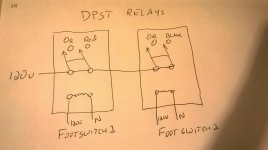
I scribbled a crude diagram. The foot switches would switch the 120V to the relay coils.
 

Attachments

  • wiring.jpg
    wiring.jpg
    45.8 KB · Views: 18
OP
C
Joined
Apr 3, 2015
Messages
8
Ok thanks for the input. I'll look at everything more closely on Monday when I get back to the shop, but I think the drum switch would tie 3 terminals together.
If I'm following you right would it be easier for me to return the footswitch and get a dpdt 2 pedal footswitch?
Thanks again for all your help


Sent from my iPhone using Tapatalk
 

KCarGuy

Well-known member
Joined
Feb 5, 2009
Messages
2,075
Location
50 miles outside Chicago, illinois
I have a Footswitch wired to an Portable 110VAC Outlet Box.

Plug the box in, then plug my Router into the Box (its on a Router Table)
This way I can keep both hands on the Wood that Is going through the Router Table and simply turn it On and Off with My Foot.

Very Handy!
 

dovco

Well-known member
Joined
Mar 8, 2015
Messages
76
Ok thanks for the input. I'll look at everything more closely on Monday when I get back to the shop, but I think the drum switch would tie 3 terminals together.
If I'm following you right would it be easier for me to return the footswitch and get a dpdt 2 pedal footswitch?
Thanks again for all your help


Sent from my iPhone using Tapatalk

I think that would work. You should double check by seeing which terminals your working drum switch connects. Use those color combinations to duplicate the same circuits on the DPST foot switches and you should be good. In the crude drawing just substitute the foot switches for the relays. Double check your wiring first, though.
 
OP
C
Joined
Apr 3, 2015
Messages
8
I think that would work. You should double check by seeing which terminals your working drum switch connects. Use those color combinations to duplicate the same circuits on the DPST foot switches and you should be good. In the crude drawing just substitute the foot switches for the relays. Double check your wiring first, though.

ok below are two more photos. One of the drum switch (or barrel switch?) and one of the motor wiring. Just want to double check this is a DPDT switch and getting a DPDT 2 pedal foot switch will work?
 

Attachments

  • image1(2).jpg
    image1(2).jpg
    139.1 KB · Views: 11
  • image2(1).jpg
    image2(1).jpg
    140.1 KB · Views: 7
OP
C
Joined
Apr 3, 2015
Messages
8
its kinda hard to see but the switch has A B 1 2 3 & 4 and looks like the part in my hand is tying together 2 groups of 3 terminals.
 
OP
C
Joined
Apr 3, 2015
Messages
8
So I think the thing I cant wrap my head around is that the motor WAS operated by one DPDT switch for forward and reverse but how to separate the forward and reverse on to two foot pedals. Any thoughts?
 

redmondjp

Well-known member
Joined
Nov 25, 2014
Messages
2,318
Location
Redmond, WA
So I think the thing I cant wrap my head around is that the motor WAS operated by one DPDT switch for forward and reverse but how to separate the forward and reverse on to two foot pedals. Any thoughts?

You have to draw out on paper the FWD and REV wiring configurations first to see it clearly. You are doing two separate things:

1) reconfiguring the directional wires, and

2) applying and removing power

I don't think you're going to be able to do it without using a couple of contactors (controlled by the footswitches) or adding separate switch contacts to the footswitches.
 
OP
C
Joined
Apr 3, 2015
Messages
8
Okay I just got A two petal foot switch, each switch is a DPDT. My thought was to take each wire split it into two wires and then on each foot switch group the wires accordingly for forward or reverse leaving the NC blank. And it almost worked! With only one pedal connected it would turn on but when the second set of wires were grouped together I would trip the breaker. I understand why this didn't work but I can't think of a way around it. Any ideas on what relays or connectors I need to make this work?


Sent from my iPhone using Tapatalk
 

redmondjp

Well-known member
Joined
Nov 25, 2014
Messages
2,318
Location
Redmond, WA
I've gone back and looked at your motor nameplate diagram (as well as spent a bunch of time on the internet searching) and I'm still not clear as to how to configure the four motor leads (with an asterisk) for FWD and REV configurations.

I'm pretty sure that you are going to be able to do it with two DPDT switches on each footswitch. You will have to wait for the motor to completely stop turning before operating the opposite direction (else it will just continue to spin in the same direction).

Do you have the drum switch wiring diagram and how the motor was connected to it? You can make your own wiring diagram if you have a continuity tester or ohmmeter and write down which contacts on the drum switch are connected to each other in both the FWD and REV switch positions. If you can post that, and what colors of the motor leads were connected to which switch positions, then we can figure it out. The drum switch contacts should either have numbers or letters, so your connection diagram will be something like this:

FWD: 1-3, 2-5; REV: 1-2, 3-5 (this is hypothetical example)
 
To avoid these ads, REGISTER NOW!
Top Bottom