To avoid these ads, REGISTER NOW!

Outlet wiring question

L5wolvesf

Well-known member
Joined
Dec 4, 2011
Messages
1,831
Location
Northern AZ
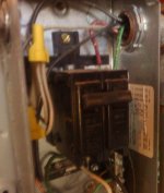
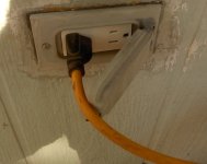
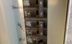
This is regarding the outlets on our small well house/shed (3 outside 1 inside). They have rarely been used but with our weather becoming colder (more often below 25), earlier and longer we need to put heat tape on the well pipes. Simple enough but, the inside outlet is a 2 prong (#4 in the circuit). So I go to change it to a 3 prong, but the third prong wire was clipped off inside the box. Same thing on the 3 prong exterior outlet (#3 in the circuit) it was tapped off of. Out of curiosity I get out my lil plug in outlet tester.
#3 reads “open hot” (but it works),
Note: there is a light bulb wired in between #2 and #3 (it works),
#2 reads – first light red no others lit – don’t know what that means (outlet is rarely used if ever),
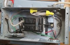
#1 reads “open hot” (rarely used if ever), #1 comes directly off the circuit breaker (sub) box in the well house.

I want to straighten this out and my first suspicion is the hots and neutrals are reversed, (black wire to brass screw white wire to silver screw) but the reading on #2 is confusing (a.k.a. WTF?).

Also, in the process I will be eliminating one of the exterior outlets.

FWIW, I’m no electrician but I can and have done simple wiring jobs.

What do y’all think of this?
Thank you
 
To avoid these ads, REGISTER NOW!

LXCam

ALLIANCE MEMBER
Joined
Apr 23, 2013
Messages
19,092
Location
AZ
Sure looks like 240 on the line side then they used the black and white as the 240 going to the load. I’d highly suggest you get a multimeter and check what voltage you truly have at the outlet before you go doing anything further.
 

SGKent

Banned
Joined
Feb 12, 2010
Messages
1,959
Location
Citrus Heights CA
I want to straighten this out and my first suspicion is the hots and neutrals are reversed, (black wire to brass screw white wire to silver screw

last someone instructed me on a 120V circuit, black (hot) to brass and white (neutral) to silver.

If 240V then the white wire, if it is also hot, would be taped black, same as the other side unless someone cut that corner - which is dangerous to the next person who handles the circuit. One has to think about what the next guy or gal in there will see, that is one of the issues with DIY. (I am DIY too but before doing something I try to read up on it first to be sure it is within my ability to get it to code and best practices.)
 
OP
L

L5wolvesf

Well-known member
Joined
Dec 4, 2011
Messages
1,831
Location
Northern AZ
Measured the voltage – 122 at the #3 exterior outlet.

The redish looking pic shows the interior 2 prong outlet (#4) on the right and the back of the exterior outlet (#3).

The other pic is the #3 exterior outlet.
 

Attachments

  • interior outlet.jpg
    interior outlet.jpg
    126.3 KB · Views: 133
  • exterior outlet.jpg
    exterior outlet.jpg
    126.7 KB · Views: 109

Blasirl

Member
Joined
Nov 2, 2019
Messages
8
Location
SE Wisconsin
You have a two pole breaker in the picture above and more than likely the well pump is 240v. It looks as if someone who had no clue wired it up. Are there any more breakers?

Measure between the two poles to see if you actually have 240v. If you do, and you have no other breakers, consider getting a small panel with more breakers. You really shold not run outlets off of the feed to the well.
 

Blasirl

Member
Joined
Nov 2, 2019
Messages
8
Location
SE Wisconsin
httpsCOLON//wwwDOThomedepotDOTcom/p/Square-D-Homeline-125-Amp-4-Space-8-Circuit-Outdoor-Main-Lug-Load-Center-with-Ground-Bar-HOM48L125GRB/100196368

Change the DOT's to periods and COLON to :
 

alfredeneuman

Well-known member
Joined
Mar 3, 2011
Messages
4,580
Location
Fullerton, CA
If 240V then the white wire, if it is also hot, would be taped black, same as the other side unless someone cut that corner- which is dangerous to the next person who handles the circuit.

Marking the white wire as hot is a recent addition to the Code.
Older installations didn't have such a requirement.
 
OP
L

L5wolvesf

Well-known member
Joined
Dec 4, 2011
Messages
1,831
Location
Northern AZ
You have a two pole breaker in the picture above and more than likely the well pump is 240v. It looks as if someone who had no clue wired it up. Are there any more breakers?

Measure between the two poles to see if you actually have 240v. If you do, and you have no other breakers, consider getting a small panel with more breakers. You really shold not run outlets off of the feed to the well.

No other breakers in the well house. Well house gets power from the main panel.

Is adding a small panel my only option? It would be good if I only had 1 outlet (interior) and the single light bulb.
 

The Cobbler

Super Moderator
Staff member
Joined
Oct 24, 2013
Messages
25,830
Location
Niagara Region, Ontario, Canada
adding a small panel your only option? first need to figure out what's going on there . do you have 240 at the pump house? what do you have for feeds to the pump house, do you have 2 hots, a neutral & ground? what is the breaker in the house that feeds all that?
 

PelicanPines

ALLIANCE MEMBER
Joined
Apr 30, 2014
Messages
38,106
Location
New Jersey, USA, Earth, My own reality
adding a small panel your only option? first need to figure out what's going on there . do you have 240 at the pump house? what do you have for feeds to the pump house, do you have 2 hots, a neutral & ground? what is the breaker in the house that feeds all that?

To answer that... how many conductors or wires go from the main to the well house?

You need three plus a ground. Usually black, red, white, bare copper ground.... ahhh ground might be green.
 
OP
L

L5wolvesf

Well-known member
Joined
Dec 4, 2011
Messages
1,831
Location
Northern AZ
adding a small panel your only option? first need to figure out what's going on there . do you have 240 at the pump house? what do you have for feeds to the pump house, do you have 2 hots, a neutral & ground? what is the breaker in the house that feeds all that?

I'll have to get that info Monday (I'll be away Sunday). Attached is an enlargement of the wiring coming into the box from the main panel.
 

Attachments

  • Well house electric box wires in.jpg
    Well house electric box wires in.jpg
    86.8 KB · Views: 132

wyliesdiesels

Well-known member
Joined
Aug 14, 2012
Messages
19,994
Location
Modesto, CA
I'll have to get that info Monday (I'll be away Sunday). Attached is an enlargement of the wiring coming into the box from the main panel.

where is this box located?

Sounds like someone ran 120v outlets off of a circuit feeding a well pump. Hopefully theyre not using the ground as a neutral.

Need to know how many wires are running to the pump house
 

teamextreme

Well-known member
Joined
Aug 10, 2013
Messages
867
Location
Lakewood, CO
You need to provide a clear pic of the entire box taken straight-on, showing all the conduits/cables that are coming into the box. The conduit in the upper right shown in your one pic of the box has more wires in it than would be necessary for the feed to the panel or the feed to the pump, so something doesn't make sense. There are 3 hots instead of 2. If the feeder to the panel and the and pump branch circuit were routed in the same conduit, this would result in 4 hots, so that doesn't explain it. But....I see a white on the breaker, so that means that conduit has 4 hots, which would explain feeder and branch circuit in the same conduit, but that means there's no neutral. If this is the case, running 120v outlets off this is a violation and a safety concern.
 

SGKent

Banned
Joined
Feb 12, 2010
Messages
1,959
Location
Citrus Heights CA
Marking the white wire as hot is a recent addition to the Code.
Older installations didn't have such a requirement.

I am not an electrician but I have electrical books from the 1980's that have that in them as a required step. I'll have to pull one out and see what it references.
 
To avoid these ads, REGISTER NOW!

Beans

Active member
Joined
Jun 26, 2019
Messages
25
Location
Backyard
You need to get an electrician or someone who knows something about electricity to look at that problem of yours. Before someone gets hurt.
 

AntonLargiader

Well-known member
Joined
Nov 20, 2016
Messages
1,372
Location
Charlottesville, VA
I think he just needs to show what's actually there so the people he's asking can understand what he has coming in. The receps seem pretty easy to re-wire if needed, assuming all of the walls are as open as the pic shows.
 

Blasirl

Member
Joined
Nov 2, 2019
Messages
8
Location
SE Wisconsin
Yes, you need to supply a picture that shows all of the connections at the well house and also how the feed is connected at the main panel. IF you have a 240v feed, which means two different legs of 120v from the main, a neutral and a ground, you can make this work with the correct sub-panel. You can use the correct feed to connect to what is usually an even number of breakers, so in your case four at a minimum. Two to supply the pump and one for the lights and one for an outlet or two.

Installing the correct panel is pretty straight forward and so is running the other circuits.

Just to comment on the colors, normally when Non-metallic sheathed cable (Romex etc.) is used, the colors are Black, Red and blue for a 240v circuit. The minimum gauge should be 12ga, but may be 10ga if it is a long run or high draw load. The black and red are the two hots, the white is the neutral and the green or usually bare wire is ground.

The only time you would change the color of a wire would be when a two wire with ground cable is used as a switch leg. You are allowed to completely cover the unsheathed portion of the white wire with another color other than white or green to signify it is the return hot leg to the load from the switch. if the wiring is in a conduit of some type, then you need to pull the correct colors.
 

alfredeneuman

Well-known member
Joined
Mar 3, 2011
Messages
4,580
Location
Fullerton, CA
I am not an electrician but I have electrical books from the 1980's that have that in them as a required step. I'll have to pull one out and see what it references.

I'm almost sure the Code to re-mark white wires as a hot first appeared in the 1999 Edition.
 

driftpin

Well-known member
Joined
Dec 22, 2016
Messages
11,192
Location
Miami-Dade/Broward Co. Florida
This is frustrating. The OP doesn't post any pics to begin. he wants to describe everything in some confusing written description, making the whole subject obtuse for me, and when he finally does post a pic, it's out-of-focus, from the wrong angle, inconclusive as-to what readers need to-see, and did I mention, just plain confusing! He wins the farcical award.

I think this guy may-be 1930's roommate.
 

Attachments

  • power supply India.jpg
    power supply India.jpg
    158.7 KB · Views: 60
Last edited:

alfredeneuman

Well-known member
Joined
Mar 3, 2011
Messages
4,580
Location
Fullerton, CA
The only time you would change the color of a wire would be when a two wire with ground cable is used as a switch leg. You are allowed to completely cover the unsheathed portion of the white wire with another color other than white or green to signify it is the return hot leg to the load from the switch.
The white wire in a switch loop is supposed to be connected to the HOT, not the switch leg.
That way you only have a black and a white to connect to the fixture, avoiding confusion.
In the new Code switch loops are prohibited anyway


The minimum gauge should be 12ga, but may be 10ga if it is a long run or high draw load.
What about #14?
 

rburke65

Well-known member
Joined
Nov 10, 2007
Messages
12,349
Location
Canfield, Ohio
A more clear photo would help. Looks as if you have 2 blacks, a red, a white and a ground from main to well house.
 
OP
L

L5wolvesf

Well-known member
Joined
Dec 4, 2011
Messages
1,831
Location
Northern AZ
First, I originally figured this was probably a simple fix of the outlet wiring and nothing to do with the well wiring. The well has been functioning without issues (except a freeze last winter) as it is since we bought the house in 2007. It is the original pump (per the well company) from about 1997. Given that I presumed the well wiring was done correctly.

Re the wiring from the main breaker box: my estimate is that run is between 50 and 75 feet (underground). Pictures to come.

Re confusing original post: the numbers are the outlets as they progress away from the well house breaker panel. I will draw up a rough diagram to clarify. I will also clarify what wires are coming in from the main panel.

Re pics: My g/f, and co-owner of the house, has a better camera but she was away this weekend. So I offered up what I could. Will get some better ones Monday when she is back from her shift tonight.

Re pics needed: do you need them with the breakers removed or? ?
 

The Cobbler

Super Moderator
Staff member
Joined
Oct 24, 2013
Messages
25,830
Location
Niagara Region, Ontario, Canada
probably a picture of the panel and the breaker that feeds the pump. is there by chance 2 breakers feeding that well house?
pictures farther back so people can see whats what with the wiring inside the well house, etc.
 
OP
L

L5wolvesf

Well-known member
Joined
Dec 4, 2011
Messages
1,831
Location
Northern AZ
Re the attached pics.

The wires on the upper right side of the box are from the main box. Those wires are: 2 black, 1 white, 1 green, 1 red. The breakers are labeled 20 amps.

The wires on the upper left side of the box (with yellow wire nuts) go to the outlets.

The wires on the lower right side of the box go to the pressure switch, which then goes to the control box behind the breaker box.

Hopefully the diagram clarifies the positions and numbering of the outlets.

The pic with tester plugged in is the #2 outlet. The first light is red with no others lit – I don’t know what that means, it is not one of the possibilities shown on the tester. I imagine it is possible the tester is not functioning correctly, but this would be the first time I’m aware of that happening.

The #1 outlet is the only GFCI outlet in the circuit.

Let me know if further info or pics are needed.
 

Attachments

  • Well outlet 2.jpg
    Well outlet 2.jpg
    122.4 KB · Views: 67
  • Well equip.jpg
    Well equip.jpg
    124.3 KB · Views: 84
  • Well House Main Box breaker.jpg
    Well House Main Box breaker.jpg
    145 KB · Views: 76
  • Well Breaker box.jpg
    Well Breaker box.jpg
    101.8 KB · Views: 257
  • Well House diagram.jpg
    Well House diagram.jpg
    74 KB · Views: 61
Last edited:

driftpin

Well-known member
Joined
Dec 22, 2016
Messages
11,192
Location
Miami-Dade/Broward Co. Florida
Much-better pics, there.

I am not an electrician.

The wiring looks pretty-sloppy, inside the box in pic #1 and outside. Isn't the white wire supposed to be wrapped with black tape, or some other color besides white or green, to show it's landed on one side of that double-breaker? I don't see any clamp or EMT or PVC plastic conduit for those wires coming into the box either.
 
OP
L

L5wolvesf

Well-known member
Joined
Dec 4, 2011
Messages
1,831
Location
Northern AZ
Is there another breaker thats feeds the oulets?

Can you take the cover off of your main panel and take pics

No other breaker in that box or the well house. The wires on the upper left side of the box (with yellow wire nuts) go to the outlets.

Yes, I'll post a pic of the main panel interior tomorrow.
 
OP
L

L5wolvesf

Well-known member
Joined
Dec 4, 2011
Messages
1,831
Location
Northern AZ
Much-better pics, there.

I am not an electrician.

The wiring looks pretty-sloppy, inside the box in pic #1 and outside. Isn't the white wire supposed to be wrapped with black tape, or some other color besides white or green, to show it's landed on one side of that double-breaker? I don't see any clamp or EMT or PVC plastic conduit for those wires coming into the box either.

I am not an electrician either, but yes it looks sloppy to me too.

Isn't the white wire supposed to be wrapped with black tape, or some other color besides white or green, to show it's landed on one side of that double-breaker? I do not know.

I noticed the lack of a clamp for the wires coming into the bottom of the box. I will address that when I do the fixes
 

mike93lx

ALLIANCE MEMBER
Joined
Dec 9, 2013
Messages
37,417
Location
Richmond, VA
No other breaker in that box or the well house. The wires on the upper left side of the box (with yellow wire nuts) go to the outlets.

Yes, I'll post a pic of the main panel interior tomorrow.

i think the question was regarding a breaker from the house that feeds it.

If this was at my house, I would rip it out and start fresh before trying to deduce my way through someone's messy work.

a single feed to the outbuilding, with two ground rods and a small panel. then feed the well and any outlets that you want. It will be clean, safe and upgradable.

If the well was fed with 4 wires, you could probably switch without running new, otherwise a new feed from the house will be needed.
 

alfredeneuman

Well-known member
Joined
Mar 3, 2011
Messages
4,580
Location
Fullerton, CA
attachment.php


You need a connector in that knockout on the bottom.
If it's outdoors, NM is limited to dry locations only and can't be used.
You also need an insulating bushing on the rigid ****** at the right top.

What a mess
 
To avoid these ads, REGISTER NOW!
Top Bottom