To avoid these ads, REGISTER NOW!

Overhead crane end trucks

gotham

Well-known member
Joined
Jul 21, 2013
Messages
213
Location
Colorado
I've been planning an overhead crane inspired by OldCarGuy. Roughly 40 x 30 building. The building has two I beams running side to side that act as rafter ties and will carry the crane. They are ~13' apart and engineered to carry a ~ 37' traveling beam and 2 ton hoist. Out at the ends of the traveling beam the capacity is reduced. I have a low headroom hoist. I'm looking for 2 ton end trucks. A couple options below:

Starke brand from Zoro ~$1000 (I can usually get 10-15% off at Zoro) Looks like $50 shipping. 23" wheel base. I think nylon wheels although I can't find that spec at the moment. I would need to widen the end trucks to fit on my bigger beams.

R&M brand This was $960 two days ago and $1060 yesterday now $1160 so might be very expensive if I don't pull the trigger soon. $600 LTL freight (I haven't tried too hard to push this down yet). 45" wheel base.

Thoughts? Other brand recommendations?
 
To avoid these ads, REGISTER NOW!

GeoBruin

Well-known member
Joined
May 5, 2018
Messages
3,750
I have no feedback for you on brands etc. I will just say that I made mine. I had some cheap Harbor freight beam trolleys that I canabalized for the wheels/axels and the rest I made from angle iron and plate. My case was a little special in that I needed the trolleys to ride on the bottom flange of the beam but carry the running beam on top. A conventional design like those pictured are even more straightforward. Literally just angle iron.

Obviously your time is woth something but when I hear that you're going to have to modify it to fit your beam anyway, I feel like you're most of the way there.
 

Attachments

  • IMG_20210906_203907_585.jpg
    IMG_20210906_203907_585.jpg
    211.5 KB · Views: 126
  • IMG_20210906_203907_835.jpg
    IMG_20210906_203907_835.jpg
    164.9 KB · Views: 100
  • IMG_20210906_203907_626.jpg
    IMG_20210906_203907_626.jpg
    110.4 KB · Views: 94
  • IMG_20210906_203907_864.jpg
    IMG_20210906_203907_864.jpg
    200 KB · Views: 105
  • IMG_20210906_203907_893.jpg
    IMG_20210906_203907_893.jpg
    165.5 KB · Views: 109
  • IMG_20210906_203907_973.jpg
    IMG_20210906_203907_973.jpg
    139.2 KB · Views: 123
  • IMG_20210906_203907_930.jpg
    IMG_20210906_203907_930.jpg
    124.9 KB · Views: 117

matt_i

Well-known member
Joined
Mar 14, 2008
Messages
10,744
Location
SE Michigan
The only exotic thing imo is the wheel with the tapered flange. The bearings are something less than 6209s, I found those once in a 5 ton hand-pushed trolley. If you had a lathe and were handy with it you could easily turn your own wheels out of a solid round of durabar (cast grey iron).

Jervis Webb makes some nice trolleys


These are *heavy duty* designed to run conveyor systems for 20 hrs/day for years on end. You just supply the structural steel.

The plastic wheels might make less noise but I wouldn't want them for fear of breakdown under load down the road.

Make sure your trolley wheels have the 1:6 slope in it if you are using "S" shapes and essentially flat if using "W" shapes in your runway rails. Also the area traversed by the crane has to be free from anything hanging from the ceiling...no conduits, cords or fans unless you have lots of headroom above. Good to plan festooning, there's a flat cable made by SuperTrex amongst others which is nicer than a round SO-style cord. Ultimate would be bus bars and contact shoes :cool:
 

b-dog

Well-known member
Joined
Apr 24, 2015
Messages
242
Location
Lakewood, CO
They are ~13' apart and engineered to carry a ~ 37' traveling beam

Am I reading that correctly, the span is 13' and designed to have a 12' cantilever on each side?! If you have the engineering calcs on that beam, I'd love to see it, if you don't mind posting....

I'd go with R&M brand only for the fact that it's well known. If you're going to have a long cantilever, I'd go with the longer wheelbase. Since the trucks are manual, in theory you could be pushing/pulling from the ends of the beam which is going to skew worse than if they were electric or had little-no cantilever. But, a shorter wheelbase will allow you to get closer to the wall.
 
OP
G

gotham

Well-known member
Joined
Jul 21, 2013
Messages
213
Location
Colorado
Thanks. I thought about making my own but couldn't find wheels that were substantially less than the end trucks. Maybe I'll look again.

I don't have a calcs handy but the plan is W18x97 for the "runways". These go across the 30' width of the building. W12x30 for the traveling beam. 4000lbs capacity out to 9.5' cantilever. At 12' cantilever 2300lbs with .5" deflection.

I have a chain driven trolley (https://www.zoro.com/harrington-hoi...0gp391hIwsD0S3UtneAaAsivEALw_wcB&gclsrc=aw.ds) so I'm hoping the deflection won't be an issue. I'm planning on lifting mostly sub 500 lbs items.

I'd like to make the end trucks motorized at some point but at least to start I'm going to have limited fab capabilities and time so I'd like to get a push system up to start with.
 

matt_i

Well-known member
Joined
Mar 14, 2008
Messages
10,744
Location
SE Michigan
When you say that the runway rails are 13' apart and the bridge rail is 37' does that mean the bridge rail is cantilevered 12' on each side of the runways (?) In other words you have 12' cantilever + 13' double-support + 12 cantilever to make the 37' total (?)

If I'm thinking about that correctly, there's could be a significant uplift on the opposite runway truck as you go farther out on the cantilever. That type of force is non-traditional in a bridge crane system. Not impossible to deal with but you need trolleys to support that upward load - and most purchased units won't have that...they are just designed for straight-down.

The other piece of advice since I read about "planning" is that your runway tracks need to be as parallel as humanly possible to avoid a bind. I think I'd cut a piece of 2x4 used with a carpenter's square to act as a perpendicular spacer and use that with a helper to set the gap before you finalize the location of the runways. If using steel posts, its going to be a fair amount of alignment work (shimming) to get it all built up perpendicular and parallel and able to withstand the side-forces as you trolley the load.

The more complicated you go, I recommend using a CAD system to make up drawings, a lot of the fabrication has to be done to "pieces" and they aren't easily modified when hanging or as they are being assembled.

I have a lot of components for a crane system and would like to build it someday if I live long enough...current shop is not setup for it.
 
OP
G

gotham

Well-known member
Joined
Jul 21, 2013
Messages
213
Location
Colorado
When you say that the runway rails are 13' apart and the bridge rail is 37' does that mean the bridge rail is cantilevered 12' on each side of the runways (?) In other words you have 12' cantilever + 13' double-support + 12 cantilever to make the 37' total (?)

If I'm thinking about that correctly, there's could be a significant uplift on the opposite runway truck as you go farther out on the cantilever. That type of force is non-traditional in a bridge crane system. Not impossible to deal with but you need trolleys to support that upward load - and most purchased units won't have that...they are just designed for straight-down.

The other piece of advice since I read about "planning" is that your runway tracks need to be as parallel as humanly possible to avoid a bind. I think I'd cut a piece of 2x4 used with a carpenter's square to act as a perpendicular spacer and use that with a helper to set the gap before you finalize the location of the runways. If using steel posts, its going to be a fair amount of alignment work (shimming) to get it all built up perpendicular and parallel and able to withstand the side-forces as you trolley the load.

The more complicated you go, I recommend using a CAD system to make up drawings, a lot of the fabrication has to be done to "pieces" and they aren't easily modified when hanging or as they are being assembled.

I have a lot of components for a crane system and would like to build it someday if I live long enough...current shop is not setup for it.
Excellent point about the uplift. I suppose I will end up building my own.

I found runway specs here: https://www.harringtonhoists.com/do...vn67cah_Series_3_End_Trucks_Owners_Manual.pdf page 20. I haven't really dug into it yet but I've brought it up to the GC and the structural steel fabricator and they say they can make it happen.

One side of the beams will be on a concrete wall. The other side will be on a steel post inside a stick wall.
 

Firebrick43

Well-known member
Joined
May 12, 2015
Messages
14,195
Location
West central Indiana
The plastic wheels might make less noise but I wouldn't want them for fear of breakdown under load down the road.
Most of your newer enclosed beam bridge and jib cranes in the last 15 years run nylon wheels without issue.
They typically locally run 6 wheels instead of 4 to handle the load. Of course for external flange trolleys it would depend on environment and how often cleaned (most are never cleaned) if nylon (or even cast iron) is a good idea or not.
 
OP
G

gotham

Well-known member
Joined
Jul 21, 2013
Messages
213
Location
Colorado
Most of your newer enclosed beam bridge and jib cranes in the last 15 years run nylon wheels without issue.
They typically locally run 6 wheels instead of 4 to handle the load. Of course for external flange trolleys it would depend on environment and how often cleaned (most are never cleaned) if nylon (or even cast iron) is a good idea or not.

I'm not expecting a lot of movement of the crane or a lot of debris to settle up there. Cleaning would be an option.

Does anyone have a good source for wheels or is breaking down trolleys the best way to get them?
 

GeoBruin

Well-known member
Joined
May 5, 2018
Messages
3,750
I would probably try mcmaster but the 2 ton HF trolley is 89 bucks. Hard to Beat. The only trick us the axels use a circlip to retain the wheel so unless you have a lathe, you're limited to the same thickness material for your chassis unless you can think of another workaround.
 
OP
G

gotham

Well-known member
Joined
Jul 21, 2013
Messages
213
Location
Colorado
I like this Webb trolley design with the non flanged wheels and the side rollers. That seems pretty easy to replicate out of angle with wheels top and bottom.

Mcmaster was the first place I looked. It seems the flanged wheels generally are designed to mount from one side while the flat wheels are designed to mount in double shear. I'll actually have plenty of space for an inner bracket to put the shafts in double shear on the top and the bottom wheels could be on a single axle.
 

Attachments

  • webb trolley.jpg
    webb trolley.jpg
    42 KB · Views: 86
OP
G

gotham

Well-known member
Joined
Jul 21, 2013
Messages
213
Location
Colorado

matt_i

Well-known member
Joined
Mar 14, 2008
Messages
10,744
Location
SE Michigan
My take on a bridge drive is that you need a small gearmotor, 3phase, VFD would be ideal so you could have slow-inch and fast-rapid travel, with double output shafts. The torque isn't too high, you can use a hollow driveshaft like DOM tubing for light weight, and the torsional stiffness in a larger cross-section, may need to weld in solid ends for keyways, appropriate support bearings, and direct-drive both wheels. That's something that has to be integrated into your trolley design. Best practice would also use taperlock couplings because the reversing motion will eventually beat the keys out of couplings which are only held by setscrews.

Its of course possible to drive both wheels with identical gearmotors, you can probably use the same VFD, but you rely on electronics rather than mechanics to prevent racking of the bridge.

I do again urge the use of CAD in your design, or at least very detailed pencil drawings....this is a complex system with many parts needing to be machined, it all has to fit together as you planned or at least have a standard to go back to for analysis when you find some sort of discrepancy. Rotary laser level would be high on my list of "tool needs" when setting the runways to the proper level. Large steel bridge cranes have the track (like a train track profile) bolted alternately to the upper flanges of the main I-beam structures so it can be tweaked every couple of feet to get the track width consistent.

You can get back some "floating" if you make the bridge rail (under)hang from a "link" which could be round, or flat, or an anchor shackle-type device. A trolley like JB Webb has side-guide-rollers to help address this. But this also consumes "headroom". And the floating also can lead to binding if its extreme, although the single-point center-driven bridge drive helps reduce that possibility.

If you add in electronic controls, it can get to be more than a trivial wiring job, placement of AC drives and routing of AC power makes it all interesting. Also urge detailed wiring diagrams for troubleshooting down the road.
 
OP
G

gotham

Well-known member
Joined
Jul 21, 2013
Messages
213
Location
Colorado
@matt_i Thanks for the input. I really appreciate it.

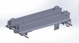
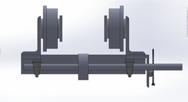
Here is what I have for CAD so far. This shows the Zoro 6' casters, roller bearings from Mcmaster, and 150mmx50mm angle (was in the profile library and seemed about right.

45 tooth ANSI 35 sprocket can probably be adapted to the inside of one or more of the drive wheels. 10 tooth sprocket on the motor. At 100 motor RPM this equals 35ft/min or 10.6m/min which seems in line with what google says is right. 100rpm 1/8hp 3ph gear motor 35 in lbs of torque. This is within the specs of the ANSI 35 chain but I have no idea if this is enough to drive the crane. Thoughts?

I agree with VFD. The small ones seem pricey compared to the 1, 2, 3 hp units I'm used to dealing with but I guess there are a lot of costs that don't scale down. I'd be interested in any info on running two motors with one VFD, I haven't heard of that before.

Are most electric motor powered cranes also mechically coupled? I see this on chain driven units.
 

Attachments

  • end truck.jpg
    end truck.jpg
    96.9 KB · Views: 69
  • chain end truck.jpg
    chain end truck.jpg
    37 KB · Views: 64

b-dog

Well-known member
Joined
Apr 24, 2015
Messages
242
Location
Lakewood, CO
Those zoro wheels are 1/4 of the cost of fully built end trucks - I'm all for DIY but it seems like buying end trucks would be the way to go.

Using 1 motor for the bridge used to be standard but is no longer common practice. However, for DIY, it might be cheaper to only use 1 central motor, especially for only 13' span. Typically, new cranes have a motor on each end truck with either VFD or contactors. You can wire 2 motors in parallel to either a VFD or contactors, this is common practice. I've only ever heard of 2 VFDs on a bridge once because the runway had a curve. At 35ft/min, I would use 1/4hp for the crane; (1) 1/4hp or (2) 1/8hp motors, or reduce your speed.

Driven end trucks have the wheels on both sides of the runway coupled together (you can see that in your chain driven picture above). I'm not saying you have to do that but if so, driven under-running trucks are going to be more complex to fabricate than the manual push/pull counterparts.

You may want to consider purchasing CMAA-74 for $105 which includes bridge motor size calcs.

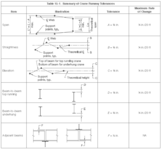
Just to clarify a few comments above, here are the tolerance(s) from CMAA 2020.

1653313749082.png
 
OP
G

gotham

Well-known member
Joined
Jul 21, 2013
Messages
213
Location
Colorado
Those zoro wheels are 1/4 of the cost of fully built end trucks - I'm all for DIY but it seems like buying end trucks would be the way to go.

Using 1 motor for the bridge used to be standard but is no longer common practice. However, for DIY, it might be cheaper to only use 1 central motor, especially for only 13' span. Typically, new cranes have a motor on each end truck with either VFD or contactors. You can wire 2 motors in parallel to either a VFD or contactors, this is common practice. I've only ever heard of 2 VFDs on a bridge once because the runway had a curve. At 35ft/min, I would use 1/4hp for the crane; (1) 1/4hp or (2) 1/8hp motors, or reduce your speed.

Driven end trucks have the wheels on both sides of the runway coupled together (you can see that in your chain driven picture above). I'm not saying you have to do that but if so, driven under-running trucks are going to be more complex to fabricate than the manual push/pull counterparts.
I think buying isn't an option anymore because of the issue of a cantilevered load lifting the opposite end truck. My current thinking is 8 wheels per end truck. 4 on the top and 4 on the bottom.

Thanks for the crane info. Do you think 35ft/min is a good speed. I can have soft start and variable speed via the VFD.

I think to make it powered I'll at least need one top and one bottom wheel driven. There could be a situation where a cantilevered load is balancing the beam so there is no weight on the opposite end truck which would mean no friction to drive. Maybe it would coast along with the loaded end truck.
 

matt_i

Well-known member
Joined
Mar 14, 2008
Messages
10,744
Location
SE Michigan
I think I'd attempt to make your bottom side wheels adjustable (slots, jack screws or shim plates) so that you can dial in the clearance you need (ideally as low as you can go and still have it run without binding). No reason you can't have a traction wheel which is actually held against the running surface of the rail - could be spring pressure or air pressure - air cylinder - to compensate for the upward deflection.

Inline with the guidance above to have rate of height change X < 1/4" in 20', part of that comes from clearance (backlash, lost motion) in the design plus the other part is from any cantilevered deflection of the I-beam ~12' out from the support. There are beam bending (deflection) equations for this, you want to take a close look at those -- don't just design for a ultimate tensile stress safety factor of 2 because you'll be way too far off when it comes to deflection. Bottom line is you don't want the load coasting "downhill" and the traction motors typically aren't designed to drive it "uphill". Its a significant factor...otherwise the specs wouldn't be written that way.

Just as a WAG no calculations, but I think you'll be into an S12 x 50#/ft or larger to deal with the cantilevered deflection @ 4000 lbs....that's a heavy piece of steel in itself @ 37' long...1850# to be precisely set right under the ceiling...now of course my numbers don't mean anything without calculations, so I would go thru that piece first as that's central to the structural functionality and then design from there.
 

b-dog

Well-known member
Joined
Apr 24, 2015
Messages
242
Location
Lakewood, CO
Ooof, driven top and bottom wheels. Without putting too much thought into it, I think I would buy the manual end trucks and add an idler wheel to run on the bottom of the beam. Your cantilever problem is similar to the trolley wheels on a hoist. A lot of hoist manufacturers use counterweights on hoists because the motor on one side is a lot heavier than the controls on the opposite side. Street (manufacturer) uses a spring-loaded idler wheel instead of counterweights.

1653342702513.jpeg

If you did all that you could run the crane manually and upgrade to driven later. If you look at Acco/Louden tractor drives/Motoveyor, they use a spring-loaded urethane wheel on the bottom to drive the tractor (the tractor pulls the hoist or crane on the beam).
 

Attachments

  • 1653343011069.jpeg
    1653343011069.jpeg
    69.6 KB · Views: 61
OP
G

gotham

Well-known member
Joined
Jul 21, 2013
Messages
213
Location
Colorado
Thanks for the thoughts. I like the OTS solution. I could even use it without the bottom wheels for lifting between the runways or light cantilevered loads where the beam would balance the load.

I like the idea of added powered wheels on the bottom, held against the beam by spring or air pressure. Bottom would be easier to design a drive system and this could double as anti uplift.
 
To avoid these ads, REGISTER NOW!
OP
G

gotham

Well-known member
Joined
Jul 21, 2013
Messages
213
Location
Colorado
I'm back on this project. Check my math here (see attached diagram). I have 4000lbs load plus 300lbs trolley cantilevered 9.5' to the right of the I beam on the right. 1110 lbs load in the center is the weight of the crane beam. I get ~2587lbs on the left I beam (ie I beam pushes down on crane beam) and ~8000lbs on the right I beam (ie I beam pushes up on crane beam).

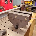
If that is right I'd like to use (6) 2000 lbs wheels per end truck. These would ride on top of the lower flange of the I beam to carry the 8000lbs load. This ductile iron wheel is my current pick.

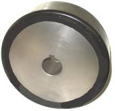
For the bottom wheels I'm thinking (4) 900 lbs polyurethane wheels. This solid poly wheel is my top choice but I would need to find a way to drive them from a shaft. This drive wheel would be nice but it's 3x the price and no weight spec given. I have an idea to mount these below the end truck using an aluminum spacer block and a pillow block bearing. I could either machine the aluminum to the proper thickness to preload the wheels or implement a spring system maybe with belvilles.
 

Attachments

  • 20220702_124557 - Copy.jpg
    20220702_124557 - Copy.jpg
    135.1 KB · Views: 51

b-dog

Well-known member
Joined
Apr 24, 2015
Messages
242
Location
Lakewood, CO
Sweet, I'm interested to see this complete!

Your math looks good to me.
30lbs/ft beam seems like it could be small for your cantilever. Have you looked at buckling? Also, consider a dynamic load under the cantilever. The force vector may not be directly inline with the web if the load swings.

Are your wheels going to be equalizing? If not, I don't think you can assume the load will be distributed evenly, especially if 1 wheel set is directly above the bridge. I would suggest keeping it simple and only using 2 wheel sets (4 total) per end truck. If you need to lower the wheel load for whatever reason, use 4 sets and make them equalizing. See EMH:

With the wheels you're looking at, you'll need guide rollers to keep the crane squared to the runway. Flanged wheels may cost more upfront but could be cheaper in the end.

You are thinking 4 bottom wheels total; 2 per end truck, right? Can you make 1 wheel on each end truck driven and the other an idler? You could connect the driven wheels with a shaft so you only need 1 motor or chain drive. I like these guys for wheels:
They have load charts for all configurations of size and wheel hardness. You could get away with 4" diam x 1.5" wide wheels if you did 2 per end truck with 60D hardness (same hardness as you linked above).

Do you know what length the end trucks will be? Max ratio of span to wheelbase is 8:1. I'm guessing you should consider your span to be 37' but quite frankly, I don't know. I would error on the long side.
 
OP
G

gotham

Well-known member
Joined
Jul 21, 2013
Messages
213
Location
Colorado
Sweet, I'm interested to see this complete!

Your math looks good to me.
30lbs/ft beam seems like it could be small for your cantilever. Have you looked at buckling? Also, consider a dynamic load under the cantilever. The force vector may not be directly inline with the web if the load swings.

Are your wheels going to be equalizing? If not, I don't think you can assume the load will be distributed evenly, especially if 1 wheel set is directly above the bridge. I would suggest keeping it simple and only using 2 wheel sets (4 total) per end truck. If you need to lower the wheel load for whatever reason, use 4 sets and make them equalizing. See EMH:

With the wheels you're looking at, you'll need guide rollers to keep the crane squared to the runway. Flanged wheels may cost more upfront but could be cheaper in the end.

You are thinking 4 bottom wheels total; 2 per end truck, right? Can you make 1 wheel on each end truck driven and the other an idler? You could connect the driven wheels with a shaft so you only need 1 motor or chain drive. I like these guys for wheels:
They have load charts for all configurations of size and wheel hardness. You could get away with 4" diam x 1.5" wide wheels if you did 2 per end truck with 60D hardness (same hardness as you linked above).

Do you know what length the end trucks will be? Max ratio of span to wheelbase is 8:1. I'm guessing you should consider your span to be 37' but quite frankly, I don't know. I would error on the long side.
Thanks for your comments. I really appreciate your time @b-dog

I'll double check with the SE but they approved the beam.

I hadn't thought about equalizing the loads on the wheels. I'll mull that for a bit.

These non flanged wheels seem roughly an order of magnitude cheaper than flanged. I haven't figure out the guide rollers yet. My first thought was some bigish ball bearings. Something softer or sprung would accommodate more error in the runway alignment, width, straightness, etc.

I was thinking two pairs of bottom wheels per end truck with one pair driven. 2587lbs max uplift, 900 lbs capacity per wheel. Lowish safety factor given that a failure only means the crane beam hits the runway. I like the wheels you linked. https://www.sunray-inc.com/load-capacities/ My reading of the chart is 47lbs for 60D hardness 4" diameter 1.5" width which seems impossibly low.

The problem with long wheelbase is it keeps the crane beam away from the walls. (Total beam length)37'/8=55.5" (Distance between runways) 13'/8=19.5". Attached drawing shows 36" wheel base. I could easily stretch it to 48". I don't think I want to go much longer than that.

Edits:
https://www.ebay.com/itm/272282280687?epid=2073156559&hash=item3f6549e2ef:g:PggAAOSwEK9TtCJK 5 ton end truck that specifies 35' max span and 33" wheelbase
https://www.hamiltoncaster.com/Cast...Wheel-Casters/FT-Part-Details/PartID/WFT-6H-1 2500 lbs flanged wheel. These are $130 each at Zoro.
 

Attachments

  • Clipboard7422.jpg
    Clipboard7422.jpg
    98.6 KB · Views: 44
Last edited:

b-dog

Well-known member
Joined
Apr 24, 2015
Messages
242
Location
Lakewood, CO
Thanks for your comments. I really appreciate your time @b-dog
Sure thing, overhead cranes are kinda my jam ;)

I'll double check with the SE but they approved the beam.
If you can post or email me calcs that would be cool. I might look at that here and let you know if I see any red flags.

I hadn't thought about equalizing the loads on the wheels. I'll mull that for a bit.

These non flanged wheels seem roughly an order of magnitude cheaper than flanged. I haven't figure out the guide rollers yet. My first thought was some bigish ball bearings. Something softer or sprung would accommodate more error in the runway alignment, width, straightness, etc.

I wouldn't bother with springs in this application, it's assumed that the bridge is going to skew. I would think at all times, half of your springs would be completely compressed and the other half would be relaxed.

I was thinking two pairs of bottom wheels per end truck with one pair driven. 2587lbs max uplift, 900 lbs capacity per wheel. Lowish safety factor given that a failure only means the crane beam hits the runway. I like the wheels you linked. https://www.sunray-inc.com/load-capacities/ My reading of the chart is 47lbs for 60D hardness 4" diameter 1.5" width which seems impossibly low.
Impossibly low indeed, you're looking at 60A which is soft, like an eraser...scroll down. Is there a reason for double the bottom wheels? I don't know see why you wouldn't just run single wheels, centered on the beam.

The problem with long wheelbase is it keeps the crane beam away from the walls. (Total beam length)37'/8=55.5" (Distance between runways) 13'/8=19.5". Attached drawing shows 36" wheel base. I could easily stretch it to 48". I don't think I want to go much longer than that.
Haha, yep, give an take for everything, such is life. I would think, guide rollers might be better than flanged wheels if you want to keep the wheelbase at a minimum. If you are doing electric, I could be convinced a short wheelbase would be ok. If the crane is manual and you'll be pushing/pulling on the load itself, at the end of the bridge beam, I would definitely go longer.

Edits:
https://www.ebay.com/itm/272282280687?epid=2073156559&hash=item3f6549e2ef:g:PggAAOSwEK9TtCJK 5 ton end truck that specifies 35' max span and 33" wheelbase
Nice! I have never noticed that. I wonder if they are able to use a shorter wheelbase due to the guide rollers. Flanged wheels are the industry standard.

https://www.hamiltoncaster.com/Cast...Wheel-Casters/FT-Part-Details/PartID/WFT-6H-1 2500 lbs flanged wheel. These are $130 each at Zoro.
 

b-dog

Well-known member
Joined
Apr 24, 2015
Messages
242
Location
Lakewood, CO
I'll double check with the SE but they approved the beam.

I semi-retract my initial impression. Just looking at basic bending/stress calcs, assuming a W10x30, you're fine*. That beam fails pretty badly for deflection with regards to cranes but that maximum allowable spec (L/600) is to ensure the trolley can climb the upslope. Allowable deflection (for cranes), at 9ft on your cantilever is about 3/16" and you're looking at almost 15/16". Might want to look into that....it would **** to pick up a load then have the trolley drift down and hit something or drift to the end of the beam which would exceed your 9ft assumption and presumably cause the beam to fail.

*Take that for what it's worth - free from some rando on an internet forum
 
OP
G

gotham

Well-known member
Joined
Jul 21, 2013
Messages
213
Location
Colorado
Thanks again.

Got it. 60D 1750lbs per wheel. Two wheels (one driven) per end truck sounds good to me.

I like these flanged wheels because they are rated for 2500lbs and they are flanged. What do you think of bringing the two shorter pieces of angle inside of the wheels (see attached images). It keeps the wheelbase longer for a given OAL.

I have a combo trolley/hoist that has a manual chain driven gear drive for translating the trolley. I'm planning electric drive for the crane beam.

W12x30 is what is specified. SE not too responsive...

Details:
Angle size? I'm thinking 6x3.5x5/16. Thoughts?
Wheels in double shear? I mostly see single sided. I have been planning on welding or bolting a piece of flat bar inboard of the wheels as a support for the other end of the axle.
Shaft size for bottom wheels? I'm thinking 1" or 1.25"
Electric Drive? What would a reasonable goal be for travel speed and motor power? My first thought was (1) VFD driving (2) of these 1/8 hp 100 rpm 3 ph gear motors (one on each end truck) with a further reduction using the chain from the motor to the drive wheel. There is also this 1/4 hp right angle 170rpm 3ph right angle gear motor. I'm not crazy about the right angle drive.
 

Attachments

  • Clipboard7722-3.jpg
    Clipboard7722-3.jpg
    92.5 KB · Views: 22
  • Clipboard7722.jpg
    Clipboard7722.jpg
    96.3 KB · Views: 25
  • Clipboard7722-2.jpg
    Clipboard7722-2.jpg
    93.7 KB · Views: 22

b-dog

Well-known member
Joined
Apr 24, 2015
Messages
242
Location
Lakewood, CO
Thanks again.

Got it. 60D 1750lbs per wheel. Two wheels (one driven) per end truck sounds good to me.

I like these flanged wheels because they are rated for 2500lbs and they are flanged. What do you think of bringing the two shorter pieces of angle inside of the wheels (see attached images). It keeps the wheelbase longer for a given OAL.
For sure! Great idea. Initial design is looking great.

Not sure if you care about OSHA and I can't remember if OSHA requires drop lugs and/or bumpers on the bridge. But, think about adding drop lugs so the crane doesn't fall if the wheel or wheel shaft fails. See the trolley you posted in #11. OSHA does require end stops and you don't want to hit the wheels against the end stops. Typically the bumper is attached to the drop lug and hits the end stop.

I have a combo trolley/hoist that has a manual chain driven gear drive for translating the trolley. I'm planning electric drive for the crane beam.

W12x30 is what is specified. SE not too responsive...

Details:
Angle size? I'm thinking 6x3.5x5/16. Thoughts?
Wheels in double shear? I mostly see single sided. I have been planning on welding or bolting a piece of flat bar inboard of the wheels as a support for the other end of the axle.
Shaft size for bottom wheels? I'm thinking 1" or 1.25"
Electric Drive? What would a reasonable goal be for travel speed and motor power? My first thought was (1) VFD driving (2) of these 1/8 hp 100 rpm 3 ph gear motors (one on each end truck) with a further reduction using the chain from the motor to the drive wheel. There is also this 1/4 hp right angle 170rpm 3ph right angle gear motor. I'm not crazy about the right angle drive.

I'm not sure about the specific sizes of parts.
Obviously, double shear is much more superior with all else considered equal but I don't think I'd worry about double shear. No end truck or trolley, that I can think of, has parts on the inside of the wheel. Just size the shafts appropriately. If you're machining the shafts, you can get high yield material that machines like butter.

Motor power is a function of acceleration. I'd error high so you don't have to buy twice. maybe 1/3 - 1/2 hp, each side?
Speed - average indoor cranes in my market go 100fpm (with 1/2-3/4hp minimum). I'm not sure how long your runway is but seems like 50fpm should be more than enough?
 
OP
G

gotham

Well-known member
Joined
Jul 21, 2013
Messages
213
Location
Colorado
Thanks for pointing out the drop lugs. I wasn't familiar with that feature.

I think the easiest thing for me to make is double sheer with shoulder screws as axles. I'm hoping to set the crane beam while the crane is lifting the other steel. I have a lathe in storage but it will remain in storage until the shop is done.

I'll probably only have ~25' of travel on the runways. I was thinking maybe 30fpm. Is that unreasonably slow? I'll keep looking for motors but it sounds like maybe even the (2) x 1/8 hp would be plausible (100fpm with 1/2 hp --> 50fpm with 1/4 hp). That part doesn't affect other parts of the design. I can play around with speeds a little using the VFD and sprocket ratios.
 
OP
G

gotham

Well-known member
Joined
Jul 21, 2013
Messages
213
Location
Colorado
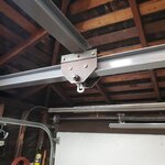
I got some parts in. Wheels look pretty beefy. That's a 1" shoulder bolt I'm going to use as an axle in double sheer. Is it standard practice to put some kind of thrust bearing or washer between the wheel and the end truck? Any thoughts on these oil embedded thrust bearings vs ultra low friction oil embedded thrust bearings from mcmaster (https://www.mcmaster.com/thrust-washers/for-shaft-diameter~1/)? SAE 30 vs SAE 80 w/ PTFE. Different temp range but same load and speed. My max speed will be <35rpm and indoors so well within specs for either.
 

Attachments

  • 20220816_111509 - Copy.jpg
    20220816_111509 - Copy.jpg
    199 KB · Views: 26

cannuck

Well-known member
Joined
Nov 30, 2021
Messages
4,657
Location
Rural SK
Sorry to have missed this thread, have been travelling a lot and only checking in once in a while.

I have built a few overhead cranes, 2 with plastic wheels (1/2 ton) that were intended to keep noise down (back yard shop) when working at night. When runways and bridge were clean and new, they worked reasonably well, but as the runways and wheels aged it is very easy to **** and lock the bridge when the trucks bind up. Most of all, the deformation of the polymer wheels means it takes a pretty fair pull to move a thousand pound load. When I did the last crane in my storage shelter, I bought some proper crane wheels (about $60 US each) and could not be happier. My 11 YO grandson can move 600 Kg (1320 lbs) located anywhere along the bridge without any truck binding. Important to make the trucks long enough and rigid enough to limit that problem. Bo.ttom line is steel wheels make the need for powered bridges and trolleys a lot less important.

All that said: I find I can buy commercial cranes and components fairly easily at auction. I scored a matching pair of 5 ton trolleys and bridges (46' span) complete with trucks for a very low price (building new shop around them, literally). I have also scored a powered 3 ton trolley for pocket change and have passed on many 1 and 2 ton winches with both cable and chain. I can not even begin to imagine having any kind of shop without good coverage from an overhead crane(s).
 
OP
G

gotham

Well-known member
Joined
Jul 21, 2013
Messages
213
Location
Colorado
Thanks cannuck. I was watching auctions for awhile but didn't see anything in my area plus I needed the bottom wheels for the cantilever force. Normally I try to buy rather than build if something is available used but here we are.
 
OP
G

gotham

Well-known member
Joined
Jul 21, 2013
Messages
213
Location
Colorado
A year later ... I'm approaching getting this thing built or at least the parts ordered. One question for @cannuck and / or the hive mind: The Hamilton steel wheels I have a small radius where the rolling surface meets the flange. I'm in the process of locating my radius gauges but it's maybe .1" The runway beam has a pretty sharp corner, definitely smaller radius than the wheel. I'm going to design in the ability to move the main angles of the end truck together or apart a little bit but it's definitely going to be difficult to adjust once the crane beam is installed. What is best practice here? Corner of the runway just at the beginning of the radius?
 

Attachments

  • 20230521_114332 - Copy.jpg
    20230521_114332 - Copy.jpg
    238.1 KB · Views: 19
  • 20230520_103457 - Copy.jpg
    20230520_103457 - Copy.jpg
    479.3 KB · Views: 28

cannuck

Well-known member
Joined
Nov 30, 2021
Messages
4,657
Location
Rural SK
A year later ... I'm approaching getting this thing built or at least the parts ordered. One question for @cannuck and / or the hive mind: The Hamilton steel wheels I have a small radius where the rolling surface meets the flange. I'm in the process of locating my radius gauges but it's maybe .1" The runway beam has a pretty sharp corner, definitely smaller radius than the wheel. I'm going to design in the ability to move the main angles of the end truck together or apart a little bit but it's definitely going to be difficult to adjust once the crane beam is installed. What is best practice here? Corner of the runway just at the beginning of the radius?
I build my crane trucks to run inside of the flange of an S beam (with fail-safe derailing provision) and mounts them to the bridge with shimmed bolts. That way I can fine tune the width (track the flange of wheels about 1/8" inside of inner edge of S beam) and alignment. Trolleys span both sides of S beam with similar mounting provisions. (my large cranes are top runners and have almost 1" total room between wheel flanges and runways)
 
Last edited:
OP
G

gotham

Well-known member
Joined
Jul 21, 2013
Messages
213
Location
Colorado
I build my camller crane trucks to run inside of the flange of an S beam (with fail-safe derailing provision) and mounts them to the bridge with shimmed bolts. That way I can fine tune the width (track the flange of wheels about 1/8" inside of inner edge of S beam) and alignment. Trolleys span both sides of S beam with similar mounting provisions. (my large cranes are top runners and have almost 1" total room between wheel flanges and runways)
So many questions...Are you saying just one set of wheels on each truck ie not both sides of runway? What's a shimmed bolt? I've been considering slots for truck to bridge adjustment and / or shims to adjust the wheels.
 

cannuck

Well-known member
Joined
Nov 30, 2021
Messages
4,657
Location
Rural SK
So many questions...Are you saying just one set of wheels on each truck ie not both sides of runway? What's a shimmed bolt? I've been considering slots for truck to bridge adjustment and / or shims to adjust the wheels.
Yes, wheels on inside of S beams. Requires absolute accuracy in runway location. Also some structure that would catch a derailment. I don't bolt the trucks directly to the bridge but have an interface of a few washers so not only width but alignment can be adjusted. Similarly, wheels have a few washers to offer second point of adjustment. In my farm storage structure my 12 YO grandson can pull both the trollery and trucks with 1200 lbs. on the hook with ease. I use a 2,000 lb ATV winch with 2 part block.
 
OP
G

gotham

Well-known member
Joined
Jul 21, 2013
Messages
213
Location
Colorado
Interesting. The drywall is being painted so the my runways are all masked off at the moment. I'll check parallelism the best I can when the painters are done. I'll almost certainly stay with wheels on both sides of both runway beams so I don't need to think about twisting those beams. I also need the anti-up lift wheels under the beams and I need some structure to mount those which could be combined with wheel mounting.
 
To avoid these ads, REGISTER NOW!
Top Bottom