To avoid these ads, REGISTER NOW!

Part needed for Sun Engine Analyzer

david5253

Active member
Joined
Nov 26, 2013
Messages
35
Location
Cripple Creek, Colorado
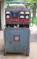
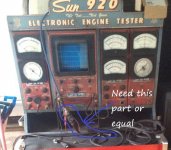
I'm currently restoring a Sun Engine Tester model 920. I have everything I need except the Pattern Pickup unit (see pictures) that is inserted into the coil on the engine and then feeds the impulses to the scope on the tester.

If I can't find an original unit, does anyone have a idea of something that would work? Looking forward to your thoughts.
 

Attachments

  • 920 EA.jpg
    920 EA.jpg
    90.1 KB · Views: 66
  • 920 part.jpg
    920 part.jpg
    122.7 KB · Views: 91
To avoid these ads, REGISTER NOW!

MBfreak

MEMBER EMERITUS
Joined
Dec 10, 2010
Messages
2,301
Location
Linkoping , Sweden
Been a while ( like 15 years) since I restored the big Sun Engine analyzer and it had the same coupling device to measure the Ignition voltage.

It is a capacitive voltage divider which is tailormade for the SUN input circuit.
Generally it is a lot like a 10/1 oscilloscope probe, but made for MUCH higher impulse voltage.
If my eroded memory serves me right the ignition scope Y axis was calibrated up to 30 kV on my SUN unit.

Like a lot of the SUN stuff it was very well made, so if you find an old one that fits your machine it is probably OK.
As usual, the weak point is the cable and plug in contact.

Keep it up.
The person who designed the two gas analyzer for SUN ( Beckman was the supplier) has been acive on GJ on and off!!

ola
 
To avoid these ads, REGISTER NOW!

laser3kw

Well-known member
Joined
Nov 17, 2012
Messages
7,276
Location
northen IL
high voltage probes for oscilloscopes are generally a few 1 meg resistors in series ( and a good insulating handle). If the OP gets cornered that may be an option to retrofit something.

PS try this site:
Sun engine analyzer site link
 
Last edited:

Grey George

New member
Joined
Jun 2, 2020
Messages
2
Location
Melbourne Australia
I am from Australia and restoring the same Sun unit.Do you know how to remove the black gauge surround to replace broken glass?Pretty rare stuff here.I have removed the gauges from the unit but simply can’t get them apart.Cheers
 

Lightning rod

Well-known member
Joined
Dec 1, 2012
Messages
283
Location
Toronto , Ontario
Thats a very small attenuator for 30 kV
They can be capacitive or resistive in nature as already mentioned
To the OP, when you say it is inserted in the coil, do you mean a lead is inserted in the
HV plugin of the coil or is there a wire wrapped around an ignition coil wire
The former means that the attenuator needs to be rated at 30 kV, the latter probably only a few hundred volts.
An attenuator rated for a few hundred volts is very easy to build
One for 30 kV rated and keep the waveform accurate, not so easy
 

MBfreak

MEMBER EMERITUS
Joined
Dec 10, 2010
Messages
2,301
Location
Linkoping , Sweden
There are two aspects of an attenuator to measure ignition pulses on a typical coil-type ignition. ( ie scope probe like unit)
The peak voltage is somewhere around 30 kV, if you check on the graticule of the scope I am pretty sure that the raster is having primary voltage graduations on the X( horizontal) lines.
The rise time is very high, the peak voltage appears in less than 10 µS.
The voltage divider is "two resistors in series" , BUT
There is capacitance over the lower resistor. Bottom terminal earth, top terminal input to scope circuit and also connection point to the top resistor which ends in the HV probe.
The product of R and C for the bottom resistor ( a few hundred kOhms) must be the same as the product of R and C for the top resistor ( several hundred megohms I Guess)
So, all other aspects apart, designing a 30 kV ignition probe requires great care.

If the two R*C ( time constants) are much different the wave form will be much distorted and the accuracy very low.

Ola
 

Lightning rod

Well-known member
Joined
Dec 1, 2012
Messages
283
Location
Toronto , Ontario
There are two aspects of an attenuator to measure ignition pulses on a typical coil-type ignition. ( ie scope probe like unit)
The peak voltage is somewhere around 30 kV, if you check on the graticule of the scope I am pretty sure that the raster is having primary voltage graduations on the X( horizontal) lines.
The rise time is very high, the peak voltage appears in less than 10 µS.
The voltage divider is "two resistors in series" , BUT
There is capacitance over the lower resistor. Bottom terminal earth, top terminal input to scope circuit and also connection point to the top resistor which ends in the HV probe.
The product of R and C for the bottom resistor ( a few hundred kOhms) must be the same as the product of R and C for the top resistor ( several hundred megohms I Guess)
So, all other aspects apart, designing a 30 kV ignition probe requires great care.

If the two R*C ( time constants) are much different the wave form will be much distorted and the accuracy very low.

Ola
Yes, sounds like you have built a few
I have made a few for test circuits in the HV LAB i used to work for
But 30 kV Rated impulse resistors Are usually 2.5 inches long or so
That is interesting packaging unless the coupler is longer
Than it looks on the pic

Something like this is about as cheap as your going to get
And will work fine for your app
https://www.alibaba.com/product-det...pm=a2700.7724857.normalList.26.2a8f79539fJ6kM

Making assumptions on your Sun input impedance and voltage max ratings
 
Last edited:
To avoid these ads, REGISTER NOW!
Top Bottom