OP

You are using an out of date browser. It may not display this or other websites correctly.
You should upgrade or use an alternative browser.
You should upgrade or use an alternative browser.
Parts for old Sears / Dunlap drill press?
- Thread starter CoconutPete
- Start date
OP
CoconutPete
Well-known member
FrankLee
Well-known member
With the spindle vertical and the chuck at the bottom, the full-length slot in the quill must be on the right with the gear rack facing you.
The dog point on the quill lock bolt/handle rides in that quill slot. It would be very apparent if the quill was upside down when the assembly is installed in the head casting.

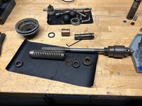
One more thing... the quill/spindle re-assembly procedure is very different than the larger ball-bearing machines.
That threaded thrust nut is the first part installed on the spindle. Thread that on all the way.

Then slide on the remaining parts.


Tighten the set screw for the upper collar into the divot on the spindle. At this point, the quill will have some vertical movement on the spindle.

Next, back-off the lower thrust nut until the quill has very little vertical movement on the spindle. The quill should turn freely on the spindle.

Lastly, tighten that small set screw in the lower thrust nut against the threads on the spindle thrust collar.


The dog point on the quill lock bolt/handle rides in that quill slot. It would be very apparent if the quill was upside down when the assembly is installed in the head casting.
One more thing... the quill/spindle re-assembly procedure is very different than the larger ball-bearing machines.
That threaded thrust nut is the first part installed on the spindle. Thread that on all the way.
Then slide on the remaining parts.
Tighten the set screw for the upper collar into the divot on the spindle. At this point, the quill will have some vertical movement on the spindle.
Next, back-off the lower thrust nut until the quill has very little vertical movement on the spindle. The quill should turn freely on the spindle.
Lastly, tighten that small set screw in the lower thrust nut against the threads on the spindle thrust collar.
OP
CoconutPete
Well-known member
Thanks Frank!
This is how it came off when I disassembled it and this is how it looks in the instruction manual.
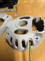
Everything goes together smoothly and it functions. The only thing I really can't figure out is that grove on one side of the quill. My design is slightly different than your pictures and nothing appears to be meant to ride in that grove.
This is how it came off when I disassembled it and this is how it looks in the instruction manual.
Everything goes together smoothly and it functions. The only thing I really can't figure out is that grove on one side of the quill. My design is slightly different than your pictures and nothing appears to be meant to ride in that grove.
Attachments


FrankLee
Well-known member
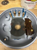
Yeah, that quill is upside down. The slot should be on the left side during quill/spindle installation into the head casting.
This looks like the quill lock. It should have a full dog point.

That collar on mine is a custom piece explained in the link below. Otherwise, the assembly is really the same as yours.
 www.garagejournal.com
Here's the quill lock. You can see the slot in left side of the quill.


This looks like the quill lock. It should have a full dog point.
That collar on mine is a custom piece explained in the link below. Otherwise, the assembly is really the same as yours.
Craftsman Drill Press
@Outlawmws I'll let Frank speak for himself, I know he's had a couple vari-slo's as I have had, both solid bar and I-beam type models. The kindest word I can come up with for the vari-slo is finicky. Others may have better experiences, but the MSA is so much more practical and low maintenance. I...
www.garagejournal.com
Here's the quill lock. You can see the slot in left side of the quill.
OP
CoconutPete
Well-known member
YESSS! Much better. Thank you!
What do you lubricate the quill and all those internal parts with? Red marine grease? White lithium grease? Motor oil?
What do you lubricate the quill and all those internal parts with? Red marine grease? White lithium grease? Motor oil?
FrankLee
Well-known member
I use 3-in-One 20 weight motor oil for all Oilite/porous bronze bushings and internal parts on the 12-1/4" drill presses.

OP
CoconutPete
Well-known member
FrankLee
Well-known member
In those situations, I use blind rivets and flatten the back side.

OP
CoconutPete
Well-known member
Yep. That's exactly what i ended up doing!
OP
CoconutPete
Well-known member
Onto the motor. Here you can see what I did with the rivets. I only had "regular" rivets so I cut them in half w/ the dremel and yanked the center piece out and then just pounded them flat on the other side. Worked pretty well.
Unfortunately the motor is what I took the fewest pictures of during disassembly so this part is a little more exciting than planned. Figuring out which way the rotor goes in will be the funnest part I guess.
Unfortunately the motor is what I took the fewest pictures of during disassembly so this part is a little more exciting than planned. Figuring out which way the rotor goes in will be the funnest part I guess.
Attachments


OP
CoconutPete
Well-known member
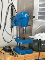
Motor works! Guess I took decent pictures.
The pulley is extremely hard to get back on, need to see if I can borrow somebody's press.
The pulley is extremely hard to get back on, need to see if I can borrow somebody's press.
FrankLee
Well-known member
The motor pulley should slide on without difficulty.
You may need to file set-screw burrs off the motor shaft, or run a 1/2" drill bit through the pulley bore.
You may need to file set-screw burrs off the motor shaft, or run a 1/2" drill bit through the pulley bore.
OP
CoconutPete
Well-known member
Well - big shout out to Frank! I'm honestly not sure I would be done by now (or ever) without all your help.
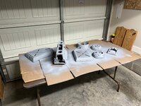
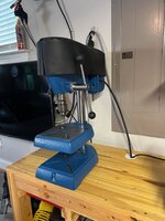
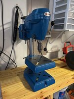
I even made a little dust cover out of some vinyl and a needle and thread.
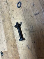
I have one bolt left over and I'm embarrassed to say I can't figure out where the heck it goes. The machine works like a dream!
I even made a little dust cover out of some vinyl and a needle and thread.
I have one bolt left over and I'm embarrassed to say I can't figure out where the heck it goes. The machine works like a dream!
Attachments

FrankLee
Well-known member
"It's a beaut, Clark"
Very nice!
That extra bolt looks like a motor mount bolt or a base bolt. It looks like you're covered tho.
Very nice!
That extra bolt looks like a motor mount bolt or a base bolt. It looks like you're covered tho.
OP
CoconutPete
Well-known member
Correct, motor mount has 4 bolts."It's a beaut, Clark"
Very nice!
That extra bolt looks like a motor mount bolt or a base bolt. It looks like you're covered tho.
Come to think of it, it may have been used to bolt the press to the thin sheet of ... something it was bolted to when I bought it.
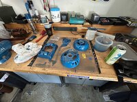
Off to do the bench grinder. That blue is just beautiful and why not have them match!