Titanium Frost
Well-known member
Background:
- Moved into a new house 4 years ago, but did not have any input into lighting or electrical design. House was 90% complete when we put our offer in.
- There were 2 photocells installed: one to operate the soffit lights and one to operate the other outdoor lights on the exterior of the house/garage.
- Both photocells are mounted remotely from the lights.
- The photocell for the soffit lights failed within 18 months, so I unhooked it, spliced the lighting wires together and turned off the breaker.
- The second photocell just failed recently, leaving the exterior in the dark (I've only noticed it now as the days get shorter).
- Both photocells installed by the builder were Intermatic K4221 photocells. I purchased a GE 18292 from HD to replace the Intermatic.
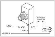
So....I went to install the new photocell and discovered that the builder's electrician only ran 2 wires + grnd to the box where the photocells are mounted. The photocells are 3 wire devices. The electrician wired the white common coming from the Intermatic to the ground in the box. I only realized this when I went to wire a new photocell.
So....I'm pretty sure that's a no no (wiring common on the device to ground). The photocell is a powered device, so I can't use the inexpensive 3 wire model as a switch. Does anyone know of a 2 wire photocell? The alternative I guess is to install a photocell at every light fixture? Not my first choice if there is a simpler solution. I currently have the 2 wires for the house/garage lights in the remote photocell box spliced together so the lights are on all the time...not ideal for energy conservation, but a deterant for the undesirables roaming the lanes at night.
The other question is...why did the Intermatic devices work in the first place? And was the incorrect wiring the cause of the very premature failures?
Thanks in advance....
- Moved into a new house 4 years ago, but did not have any input into lighting or electrical design. House was 90% complete when we put our offer in.
- There were 2 photocells installed: one to operate the soffit lights and one to operate the other outdoor lights on the exterior of the house/garage.
- Both photocells are mounted remotely from the lights.
- The photocell for the soffit lights failed within 18 months, so I unhooked it, spliced the lighting wires together and turned off the breaker.
- The second photocell just failed recently, leaving the exterior in the dark (I've only noticed it now as the days get shorter).
- Both photocells installed by the builder were Intermatic K4221 photocells. I purchased a GE 18292 from HD to replace the Intermatic.
So....I went to install the new photocell and discovered that the builder's electrician only ran 2 wires + grnd to the box where the photocells are mounted. The photocells are 3 wire devices. The electrician wired the white common coming from the Intermatic to the ground in the box. I only realized this when I went to wire a new photocell.
So....I'm pretty sure that's a no no (wiring common on the device to ground). The photocell is a powered device, so I can't use the inexpensive 3 wire model as a switch. Does anyone know of a 2 wire photocell? The alternative I guess is to install a photocell at every light fixture? Not my first choice if there is a simpler solution. I currently have the 2 wires for the house/garage lights in the remote photocell box spliced together so the lights are on all the time...not ideal for energy conservation, but a deterant for the undesirables roaming the lanes at night.
The other question is...why did the Intermatic devices work in the first place? And was the incorrect wiring the cause of the very premature failures?
Thanks in advance....

 (1/2 educated guess) is that the cell must be connected in series with the load it is switching. It will still require a neutral.