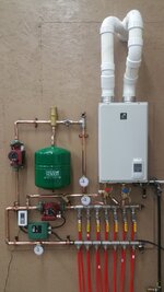
So I did my own radiant floor heat last year and it came out great. It's a primary/secondary setup utilizing a takagi 140k on demand unit. The efficiency seemed great and being a modulating boiler you could tell it always ran on the first stage of burners. The specs of my barn are 1440 sq ft with 7 loops at 250ft per loop. A little over kill but it seems to heat up quick if I want to raise the temp. Now my friend is building a 3500 sq ft shop and wants me to build the radiant heat panel for him, I'm thinking I can duplicate my setup using the same boiler but going the next size up for circulating pumps and using 3/4 copper for the primary and 1" for the secondary. I'm planning 1 zone, 7 loops of 5/8"x500 ft. Pics of my setup I did last year that I plan on copying

You are using an out of date browser. It may not display this or other websites correctly.
You should upgrade or use an alternative browser.
You should upgrade or use an alternative browser.
Please double check my radiant floor heat idea
- Thread starter Earp69
- Start date
Those units have a 4gpm max flow. They are not condensing .. so they may with radiant depending on use,
I think you have posted this before. You have the primary/ secondary backwards. The primary should loop around the boiler and the close spaced tee should be out to the secondary. The safety valve should be mounted right at the outlet of the unit as in the manual.
I heat my whole house at over 4k sf with 60k of boiler -- so your friend should do a load to see what unit to use.
Today with the modern ecm pumps -- they are worth getting. More flexibility and they use 1/4 of the power. The Alphia two can even get you a preset temp delta. You don't need a bigger pump -- just keep the loops under 300. 250 even better. It's always better to have more pipe and one more loop
theoldwizard1
Well-known member
More than double the square footage and you think you can use the same heat source. I doubt it would work.
Also double the length will mean the return water temperature will be much colder.
Also double the length will mean the return water temperature will be much colder.
Are you speaking from actual radiant heat experience? Or just guessesMore than double the square footage and you think you can use the same heat source. I doubt it would work.
Also double the length will mean the return water temperature will be much colder.
This unit is condensing, and max flow is more than 4gpm. Not sure how my system worked so well for being so wrong as your saying? Also I'm planning 5/8 pex for his setup not 1/2 inch so 500 ft loops are feasibleThose units have a 4gpm max flow. They are not condensing .. so they may with radiant depending on use,
I think you have posted this before. You have the primary/ secondary backwards. The primary should loop around the boiler and the close spaced tee should be out to the secondary. The safety valve should be mounted right at the outlet of the unit as in the manual.
I heat my whole house at over 4k sf with 60k of boiler -- so your friend should do a load to see what unit to use.
Today with the modern ecm pumps -- they are worth getting. More flexibility and they use 1/4 of the power. The Alphia two can even get you a preset temp delta. You don't need a bigger pump -- just keep the loops under 300. 250 even better. It's always better to have more pipe and one more loop
The 140,000 BTU boiler to too large if anything!More than double the square footage and you think you can use the same heat source. I doubt it would work.
Also double the length will mean the return water temperature will be much colder.
Yes, old wizard is thinking forced air terms, not radiant floor heatThe 140,000 BTU boiler to too large if anything!
Never discount luck in lifeThis unit is condensing, and max flow is more than 4gpm. Not sure how my system worked so well for being so wrong as your saying? Also I'm planning 5/8 pex for his setup not 1/2 inch so 500 ft loops are feasible
I do now see that you have a PVC drain off the unit ..... lots of those Takagi are not condensing so I made a quick assumption. I jumped on the 140k and the specifications show 4gpm ... about right for a 140k on-demand.
Explaining why a particular system may be piped incorrectly and still work ... Radiant is very forgiving. As long as BTU's get into the slab -- the slab is going to warm . But -- it's piped incorrectly and there is no reason to repeat the mistake and risk that a different flow causes problems. We learn and improve as we go forward.
Is there a reason for the larger pipe. 1/2 is typically not only the cheapest way to go -- it's makes for a better system in most cases. The surface area of the 5/8 is not that much greater --- so the heat transfer is not that much more and 5/8 holds more water ..so the whole assembly just takes longer to heat and stabilize. Especially pushing out the loops to the max. All makes for slower response. PEX is cheap and so are extra spaces on a manifold --- shorter closer loops keep the delta tighter and make for a better more efficient system.
My last plate system used 3/8 tubing .... shorter loops and more of them vs 1/2. But -- you don't lose output or increase head as long as the loops are correct. Long loops of any size increase head
Last edited:
BTU's are BTU's .... while modulation does solve some of the problems and w/ condensing you do want some head room on BTU output if the heating season would cause the unit to fully fire for long parts of the winter. But -- 140k for 1400 is only going to need to run on the lowest output most of the time ... depending on the unit design. Some units are designed to fire on high and then drop down .... others start low and ramp up. Often ODR is the latter. The whole point of radiant is low and slow (long run times) for max efficiency -- same with new boilers w/ small mass heat exchangers.Yes, old wizard is thinking forced air terms, not radiant floor heat
theoldwizard1
Well-known member
LOGIC !Are you speaking from actual radiant heat experience? Or just guesses
Correction, it's 110k btu and 6.6gpm max flow. When it first fires it lights all the 3 stages and once it sees the delta is below setpoint it drops to just the one stage which only takes about 5 sec. Can you please draw or give me an example of how my setup should be? I'm having a hard time seeing what your saying.Never discount luck in life
I do now see that you have a PVC drain off the unit ..... lots of those Takagi are not condensing so I made a quick assumption. I jumped on the 140k and the specifications show 4gpm ... about right for a 140k on-demand.
Explaining why a particular system may be piped incorrectly and still work ... Radiant is very forgiving. As long as BTU's get into the slab -- the slab is going to warm . But -- it's piped incorrectly and there is no reason to repeat the mistake and risk that a different flow causes problems. We learn and improve as we go forward.
Is there a reason for the larger pipe. 1/2 is typically not only the cheapest way to go -- it's makes for a better system in most cases. The surface area of the 5/8 is not that much greater --- so the heat transfer is not that much more and 5/8 holds more water ..so the whole assembly just takes longer to heat and stabilize. Especially pushing out the loops to the max. All makes for slower response. PEX is cheap and so are extra spaces on a manifold --- shorter closer loops keep the delta tighter and make for a better more efficient system.
My last plate system used 3/8 tubing .... shorter loops and more of them vs 1/2. But -- you don't lose output or increase head as long as the loops are correct. Long loops of any size increase head
You mention 140k in the post above ... That's all I can go by as the units all look the same.
The problem you have with these "on - demand" -- they are designed to make hot water. If you look at the pipe diagram they show in the manual -- the heat loop is out to an air handler. That's going to want -- 140 degree water. Also -- the diagram is very poor in its ability to show relative placement of devices .... it's a schematic.
But -- it clearly shows the pump of the primary -- pumping into the heater. This is how they always have to be on on these units. The pump needs to be overcoming the head of the heater. Unless I'm missing something where the pipes cross .. the pump is not doing that and it's too far away. Also -- you want the t&P valve just as it comes out of the heater .. as they show it. This is the hottest point and where it needs to be.
Now ---- go look at primary secondary diagram someplace that's better illustrated. The primary loop is .... well -- a loop. The water goes around and around. The secondary is two "T" close spaced ( determined by pipe diameter size) with the pump pulling the water out. You have the primary going into the secondary ... it's backward. I'm trying to figure out how it even works ... and what's going on with the pumps fighting each other.
Does this photo change anything? And the pressure relief is literally 2 foot out from the outlet of the heaterYou mention 140k in the post above ... That's all I can go by as the units all look the same.
The problem you have with these "on - demand" -- they are designed to make hot water. If you look at the pipe diagram they show in the manual -- the heat loop is out to an air handler. That's going to want -- 140 degree water. Also -- the diagram is very poor in its ability to show relative placement of devices .... it's a schematic.
But -- it clearly shows the pump of the primary -- pumping into the heater. This is how they always have to be on on these units. The pump needs to be overcoming the head of the heater. Unless I'm missing something where the pipes cross .. the pump is not doing that and it's too far away. Also -- you want the t&P valve just as it comes out of the heater .. as they show it. This is the hottest point and where it needs to be.
Now ---- go look at primary secondary diagram someplace that's better illustrated. The primary loop is .... well -- a loop. The water goes around and around. The secondary is two "T" close spaced ( determined by pipe diameter size) with the pump pulling the water out. You have the primary going into the secondary ... it's backward. I'm trying to figure out how it even works ... and what's going on with the pumps fighting each other.
Attachments

like2wheel
Well-known member
Also wondering what diameter piping should be used for each loop.
Seems like the primary should have a larger diameter, & the secondary should be same or smaller than the primary?
Seems like the primary should have a larger diameter, & the secondary should be same or smaller than the primary?

They use a valve at the Junction ... also it's a boiler (electric) -- so I don't know the head. Some of those are a little tank with low head.I copied the hydrosmart menards sells, so the system the sell is incorrect?
The junction (between the "T") is often called the decoupler. It's just pipe on a simple system -- spacing based on the pipe size --- pipe size on flow.
They have a devise that is acting as a balance valve -- flow controller -- diverter could be called a few things. It's going to change the fluid dynamics
Last edited:
No. What you call the primary pump -- the upper. It's pulling water from the hot side .... the primary should feed to the cold on these.Does this photo change anything? And the pressure relief is literally 2 foot out from the outlet of the heater
I can't tell exactly what direction the other pump is ..... it should be pushing water to the floor. Do you have that reversed as well and that's providing the fight (two pumps) feeding into the heater?
I get that the T&P is two feet away .. they show it right after .... just like most do. You will have cooling -- the valve is a safety. My point was when you do a new one .... you fix the things off.
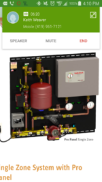
Sorry for the delayed response, been a busy few days at work. So is this how your saying I should have it piped? I'm not opposed to changing my own setup if this will increase efficiency.No. What you call the primary pump -- the upper. It's pulling water from the hot side .... the primary should feed to the cold on these.
I can't tell exactly what direction the other pump is ..... it should be pushing water to the floor. Do you have that reversed as well and that's providing the fight (two pumps) feeding into the heater?
I get that the T&P is two feet away .. they show it right after .... just like most do. You will have cooling -- the valve is a safety. My point was when you do a new one .... you fix the things off.
Attachments

This is from the Viessmann 200 application guide -- can download and see page in color. I'm trying to find one close to how you have it
It shows the close spaced tees layout on the right. The pump is pumping into the boiler -- the cold input. See how this showes the T&P valve just at the hot exit?
With close spaced "T" you need to measure the distance between the "T" -- there is a formula for the distance based on the pipe size and then you want a defined amount of straight pipe on each side. The close spaced tee is the simple version of the Low Loss Header. You are creating what is called hydraulic separation .... a fancy name for .. give the boiler the flow it wants and the system side the flow it wants. On smaller systems the close tee will work .... when you get to a larger system with lots of loops there is too much flow needed and the low loss header must be used.
If you notice .... Viessmann likes the air separator and fill valve on the system side (secondary loop) with the pump "pumping away" from the air separator. There is a reason for that point. Has to do with pressures and how air works in water. Some layouts do show the air separator on the primary loop on the hot exit from the boiler -- the theory there is heat. But the pump in all cases is on the cold side of the boiler.
The secondary pump is flowing towards the radiant loops --
My comments on this thread ... and the other when you posted was not to be critical. It was for those looking at your setup to understand where the potential problems are. I can't be there to flip on the boiler on cold startup and see how the boiler works ... on initial start with all the water cold .... it should run on high as the cold water coming in from the floor should be enough to keep the primary loop cold. I can't tell how yours flows. Understand? Since it can modulate ... even if the flow is poor -- it will drop down and just power on from there. Take longer -- but the boiler will not over heat.
Radiant is very forgiving .... It's not really a question of more efficient. It really about boiler protection and proper flow w/ the smallest pumps.
I will look for another diagram .... The viessmann guide is very good
Attachments
I appreciate the constructive criticism, if I knew it all I wouldn't be here asking for help right? Sorry if I came across defensive, I'm just trying to relay my thoughts on how it works/why i did it, not defend that my way is right. What's the best affordable low loss header? Im doing nine 400' loops of 5/8 pex and am wondering if the closely spaced tee is no longer an option with that many loops?This is from the Viessmann 200 application guide -- can download and see page in color. I'm trying to find one close to how you have it
It shows the close spaced tees layout on the right. The pump is pumping into the boiler -- the cold input. See how this showes the T&P valve just at the hot exit?
With close spaced "T" you need to measure the distance between the "T" -- there is a formula for the distance based on the pipe size and then you want a defined amount of straight pipe on each side. The close spaced tee is the simple version of the Low Loss Header. You are creating what is called hydraulic separation .... a fancy name for .. give the boiler the flow it wants and the system side the flow it wants. On smaller systems the close tee will work .... when you get to a larger system with lots of loops there is too much flow needed and the low loss header must be used.
If you notice .... Viessmann likes the air separator and fill valve on the system side (secondary loop) with the pump "pumping away" from the air separator. There is a reason for that point. Has to do with pressures and how air works in water. Some layouts do show the air separator on the primary loop on the hot exit from the boiler -- the theory there is heat. But the pump in all cases is on the cold side of the boiler.
The secondary pump is flowing towards the radiant loops --
My comments on this thread ... and the other when you posted was not to be critical. It was for those looking at your setup to understand where the potential problems are. I can't be there to flip on the boiler on cold startup and see how the boiler works ... on initial start with all the water cold .... it should run on high as the cold water coming in from the floor should be enough to keep the primary loop cold. I can't tell how yours flows. Understand? Since it can modulate ... even if the flow is poor -- it will drop down and just power on from there. Take longer -- but the boiler will not over heat.
Radiant is very forgiving .... It's not really a question of more efficient. It really about boiler protection and proper flow w/ the smallest pumps.
I will look for another diagram .... The viessmann guide is very good
I appreciate the constructive criticism, if I knew it all I wouldn't be here asking for help right? Sorry if I came across defensive, I'm just trying to relay my thoughts on how it works/why i did it, not defend that my way is right. What's the best affordable low loss header? Im doing nine 400' loops of 5/8 pex and am wondering if the closely spaced tee is no longer an option with that many loops?
Have you done the PEX loops ? Just wondering why you are using the 5/8
The need for a LLH is BTU transfer. You need "X" flow to get "Y" BTU's ...... the whole system is about moving the BTU's. You can only flow so much water through the close spaced "T" . High temp water will transfer more heat .... but radiant is low temp.
It all starts with that heat load calculation
Main reason for 5/8 was to reduce the size of manifold, which is a poor reason I know. Unfortunately he's already received all the pex. I'm not sure how to do a heat load Calc because he's not sure what or how he plans on insulating it which doesn't make things any easier. All i know is it's 3500 sq ft, 18 foot ceilings, one 14x14 door, one 12x12 door, and one 10x10 door and all are r10. Tried talking him into r17 doors but he wouldn't go for it
You should be able to punch that in ..... what's the overall insulation? What you have to understand is the flow ...... GPM needed and do you have a large enough pipe.
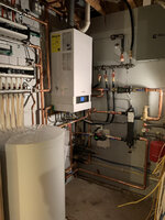
Wish I had a better picture of my current project. If you look in the middle of the pipes you can see the low loss header (black rectangle) . the pipes on the left are the boiler loop. You see how the pipes are smaller .. the right side is the secondary out to the PEX loops. The flow is greater -- so the pipe is larger. If you follow the secondary pipe around and look left from the pump you can see a 90 off the bottom -- that goes down and under a floor to a remote location with two additional manifolds. One is 8 loops 1/2" pex and the other is 11 loops of 3/8 pex -- all manifolds get flow from that one smart pump. You can see the two additional manifolds on top of the indirect tank. The pipe continues past the 90 and goes up over the boiler. It's a small mechanical room for a complex project .
It's often easier in a big building to use two manifolds and connect them together. this cuts down on the loop lengths and the back and forth tubing to get out to the far away parts of the building
Attachments
Last edited: