To avoid these ads, REGISTER NOW!

Point Loading Steel Beam Calc's

shooon

Well-known member
Joined
Aug 30, 2016
Messages
68
Location
Dawson Creek, BC
Just wondering if anyone can help me confirm my math for a beam I installed- the plan is to use the beam with a chain fall.

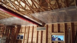
I incorporated a 24' W8X31 steel beem across the span of my garage. The beam is supported by 12" doubled up LVL's spanning 48". Once the inside wall sheathing is up I plan to lag bolt some steel plates into the LVL and then bolt the beam down to the plates. The idea behind the plates is to secure the beam from shifting around from accidental side loading.

When doing the math on the beam, I wanted it to be able to point load 1000lbs (1/2 ton) at 12' span of the beam since that should be the weakest point. I then doubled the result for safety margin.

W8x31 with 24' span I came up with 1900lbs (1.9 kips/ft) max weight before bending became a concern.
 

Attachments

  • 20161202_171626.jpg
    20161202_171626.jpg
    144.4 KB · Views: 174
To avoid these ads, REGISTER NOW!

LX-Markham

Well-known member
Joined
Apr 27, 2013
Messages
2,929
Location
Markham, Ont.
If I was at the office, I'd calc this in a second, but it's the long weekend and I didn't bring my steel book home with me.
If nobody else gets you an answer, I'll do it next week. I don't do many hoist beams, but off the top of my head I think you need to apply a 1.2 factor to you load for impact loading (limit states design).

Can you confirm if the steel is 300W or 350W?
And I assume you are not concerned about deflection? 24' is a long span for an 8" beam. It may have the strength, but it's likely going to bend quite a bit.
And it doesn't appear as if the top flange is braced. So the strength will be based on an unsupported length of 24'.
 
Last edited:

DblDog

Member
Joined
Jul 11, 2017
Messages
16
Pending LX's review, check out amesweb.info, they have a quick calculator for simple spans with a concentrated load. LX's comment regarding deflection is correct...if the chain fall is on a trolley, meaning it could slide from one support to the opposite side, too much deflection under load will cause the trolley travel to mid span.
 
OP
S

shooon

Well-known member
Joined
Aug 30, 2016
Messages
68
Location
Dawson Creek, BC
If I was at the office, I'd calc this in a second, but it's the long weekend and I didn't bring my steel book home with me.
If nobody else gets you an answer, I'll do it next week. I don't do many hoist beams, but off the top of my head I think you need to apply a 1.2 factor to you load for impact loading (limit states design).

Can you confirm if the steel is 300W or 350W?
And I assume you are not concerned about deflection? 24' is a long span for an 8" beam. It may have the strength, but it's likely going to bend quite a bit.
And it doesn't appear as if the top flange is braced. So the strength will be based on an unsupported length of 24'.

Thank you.

I've been using http://webstructural.com/beam-designer.html to get some numbers.

Yes, the beam is completely unbraced for the 24' length.
As far as steel grade I can't find mention of 300W or 350W. However my invoice from the steel supply states 50 KSI / A992 which a quick google search says is the same as 350W ?

Realistically this thing won't be used mid span, likely 6-8' span. I just was trying to figure out what my safe working loads might be. Prior to buying the beam nobody wanted to talk to me about it due to liability concerns, which I can understand.. Just wish I had thought to come here first.

Deflection is a concern now that you mention it - the sliding of the beam trolley due to deflection. I might have to rig up a brake to assist with that if I can't find a way to limit deflection.
What would you recommend for bracing and do you think it's possible given my pictured setup ?
 
Last edited:

spudley

Well-known member
Joined
Dec 27, 2016
Messages
702
Location
Northeast Wisconsin
Thinking out loud here but could you use a sliding column (post) and move it from the wall to the center when using the hoist?
 

ard

Well-known member
Joined
Feb 16, 2015
Messages
4,391
Location
Sierra Foothills... California
Thinking out loud here but could you use a sliding column (post) and move it from the wall to the center when using the hoist?

Good idea.

You could have two load limits- one far greater with the temp column clamped in place. And also know that even at the lower limit the column would control deflection and let you move the load easier.
 

brownbagg

Well-known member
Joined
Mar 20, 2006
Messages
5,208
i would be more concern with the connection at the wall than bending the beam
 

Chris705

Well-known member
Joined
Nov 1, 2012
Messages
834
Location
The Finger Lakes of NY
schooon - looks like you used roof trusses, any idea if there is extra bottom chord loading that you are not taking advantage of? You might be able to run a couple lvl strongbacks across multiple trusses and pick up son extra loading capacity. Your 1000 lbs loading is fairly light in the scheme of things.
 

johninct

Well-known member
Joined
Dec 21, 2010
Messages
2,593
The connection at the wall and deflection have to do with each other.
 
OP
S

shooon

Well-known member
Joined
Aug 30, 2016
Messages
68
Location
Dawson Creek, BC
Thinking out loud here but could you use a sliding column (post) and move it from the wall to the center when using the hoist?

That's a great idea!! That would allow increased loading without the hassle of a permanent post in the middle of the garage.

i would be more concern with the connection at the wall than bending the beam

For the wall connection I have a large piece of 12" C channel that will be lag bolted to the wall, into the LVL. The upper lip of the c channel will be drilled and bolted into the bottom flange of the beam on both sides.

schooon - looks like you used roof trusses, any idea if there is extra bottom chord loading that you are not taking advantage of? You might be able to run a couple lvl strongbacks across multiple trusses and pick up son extra loading capacity. Your 1000 lbs loading is fairly light in the scheme of things.

Also a great idea!
My only concern is the bottom chords of these trusses are 2x4's - I would have to involve a structural engineer or truss expert before trying that. I wonder how much load each truss could support individually?

A w8x31 is good for 1 ton at 20' span, so your calcs are close. At 1/2 ton you should be good if your supports are good.

Thank you.
Good to know numbers are close, I thought I had overestimated but apparently fell short :sad:
 

ard

Well-known member
Joined
Feb 16, 2015
Messages
4,391
Location
Sierra Foothills... California
Generally roof trusses will be specd to only carry the load of a ceiling, insulation, lights. So like 10lbs/sqft?? If they were specd for more, you might be able to use that- I think that was the suggestion.

The drawing from the truss mfg should list it.
 

Snap50

Well-known member
Joined
Dec 29, 2009
Messages
145
Location
New England
With your unbraced beam lateral buckling failure is the concern and greatly reduces the beam's carrying capacity.

I didn't run the calcs but assuming what others have advised is correct, you want to secure the ends so the beam is restricted from rotating and movement and be careful how you load it. Don't hang your weight from one side of the beam which would cause it to roll over.

There are ways to reinforce the flanges along the length if you find that you need more load capacity from the "unbraced" beam. Alternatively there may be a way to introduce some lateral braces to have a similar effect.
 
To avoid these ads, REGISTER NOW!

Snap50

Well-known member
Joined
Dec 29, 2009
Messages
145
Location
New England
schooon - looks like you used roof trusses, any idea if there is extra bottom chord loading that you are not taking advantage of? You might be able to run a couple lvl strongbacks across multiple trusses and pick up son extra loading capacity. Your 1000 lbs loading is fairly light in the scheme of things.

Prefab trusses are Never overdesigned. That is the point of economy.
One-thousand pounds is alot for a 24' truss, presumably spaced at 2 feet o/c.
That is more than 2/3 of the required snow load on my town here in the northeast.
 

matt_i

Well-known member
Joined
Mar 14, 2008
Messages
10,724
Location
SE Michigan
If you are worried about buckling of the top flange the classic fix is to put a "cap channel" on it which emulates a "T" shape, like the U of Tennessee's logo. It has to be stitch welded which is more trouble now.

I would never use a lag bolt for attaching anything I cared about, poor material, split wood like crazy due to the archaic point design. Source GRK-RSS screws, so much better. ABC-Spax also has a similar set of products.

Your deflection looks good, I get less than 3/16" at the center. Well less than L/480.

I would X-brace that wall (and the other equivalent behind)). Just because you have the column supported doesn't mean the wall can't fold over in the direction of the plane if a load does something you didn't think of like sway on a chain. The link is for a Simpson 16ga flat strap you nail to every stud and top and bottom plate with #10s I think.

http://www.homedepot.com/p/Simpson-Strong-Tie-25-ft-16-Gauge-Coiled-Strap-CS16-R/100375320
 

bad_idea

Well-known member
Joined
Jun 11, 2011
Messages
4,332
Location
Pasquotank, NC
Thinking out loud here but could you use a sliding column (post) and move it from the wall to the center when using the hoist?

I would suggest a large rolling base for said column to make it easier to move and also to spread out the load. Then build some kind of threaded shaft into the support pad to preload the support point to avoid deflection. Perhaps a transmission support for use with a lift would do it?
 
OP
S

shooon

Well-known member
Joined
Aug 30, 2016
Messages
68
Location
Dawson Creek, BC
If you are worried about buckling of the top flange the classic fix is to put a "cap channel" on it which emulates a "T" shape, like the U of Tennessee's logo. It has to be stitch welded which is more trouble now.

I would never use a lag bolt for attaching anything I cared about, poor material, split wood like crazy due to the archaic point design. Source GRK-RSS screws, so much better. ABC-Spax also has a similar set of products.

Your deflection looks good, I get less than 3/16" at the center. Well less than L/480.

I would X-brace that wall (and the other equivalent behind)). Just because you have the column supported doesn't mean the wall can't fold over in the direction of the plane if a load does something you didn't think of like sway on a chain. The link is for a Simpson 16ga flat strap you nail to every stud and top and bottom plate with #10s I think.

http://www.homedepot.com/p/Simpson-Strong-Tie-25-ft-16-Gauge-Coiled-Strap-CS16-R/100375320

Thank you.

I've seen those GRK-RSS screws at the hardware store, they look pretty solid I'll give them a shot!

for the 3/16" deflection you came up with, were you using 1000lb loading or 2000lb ?

With regards to wall bracing; I've placed 2 rows of blocking 4' apart across the entire wall (ie: one row at 4' height, another row at 8') Also the interior wall will be 5/8" plywood- so it will be structural sheathing in a sense. I'm wondering if I should still go with the strapping you recommended or if the blocking and sheathing are enough?

I would suggest a large rolling base for said column to make it easier to move and also to spread out the load. Then build some kind of threaded shaft into the support pad to preload the support point to avoid deflection. Perhaps a transmission support for use with a lift would do it?

That's another great idea, thank you.

I was originally thinking something like a tele-post type setup. I was also maybe thinking of buying a set of vehicle dollies and modifying one of them to support the post- they can provide 4000lbs support and still move around. The hydraulic trans lift idea sounds pretty awesome though- probably a lot easier to setup and move around.
 

ptgarcia

Well-known member
Joined
Nov 15, 2016
Messages
1,202
Location
Alta Loma, CA
With changes in length due to deflection and temperature should one end of the beam be pinned and the other on roller (or other free end)? Just thinking back to my college structures classes.
 

matt_i

Well-known member
Joined
Mar 14, 2008
Messages
10,724
Location
SE Michigan
With changes in length due to deflection and temperature should one end of the beam be pinned and the other on roller (or other free end)? Just thinking back to my college structures classes.

This is a good point but I think one could get away with oversizing the holes slightly, for example, if using a 3/8" screw, drill a 1/2" clearance hole. Just so the building and beam could move very slightly relative to each other if necessary.

Imo, the fixed-pin and roller support from Statics 101 is basically just so the beam shows the assumptions made in the theory which allow no moments at either end and the length isn't constrained. But those are conservative-worst case.

In the deflection calc I used 1000 lbs.

Relative to the x-bracing, in my opinion no reasonable amount of cross-blocking can do the same thing. The reason is the cross-blocking/fire blocking can only support a very small moment, its usually toenailed to the vertical 2x which is also structurally iffy. Placing the strap in tension (as the wall racks) is very strong. The nails are in shear which is also best-case for connecting the timber to the flat steel. The second part of the "X" makes sure you are covered for both directions as the strap can't support any compression. It would rely on the other member.
 
Last edited:

Road_runner

Well-known member
Joined
Jun 28, 2015
Messages
74
Location
Somewhere around here (in the UK)
I did a similar calc for a garage here in the uk. Based on a 1 tonne (1000kg or 2240lb) load, using S275 steel, the most efficient section was a 152 x 152 x 23 UC (universal column) section for a 7m (just under 24 ft) span.

Deflection was one of the criteria. The UC section is more compact than the beam and therefore resists buckling better than a more slender UB section. It also means it takes less headroom than a UB.
 

Beemie

Member
Joined
Dec 6, 2016
Messages
23
With changes in length due to deflection and temperature should one end of the beam be pinned and the other on roller (or other free end)? Just thinking back to my college structures classes.

I think you're over thinking it. Theoretical vs real world.
Most steel beams in buildings are designed as "simple span" which is as you've described pin/roller but I am sure you have never seen a steel beam not connected at both ends. We don't emulate roller supports on anything except very very long members like bridges, etc.

You need to be more concerned about keeping your beam from moving and rolling over.
 
Last edited:

handymancanfixit

Well-known member
Joined
Aug 25, 2014
Messages
57
Location
Winston Salem, NC
I get the same deflection as matt_i, less than 3/16" for a 1000 lb point load at the center. You only get 5/16" deflection with a 2000 lb load and less than 1/2" with a 3000 lb load.

You should definitely triangulate the ends to insure against rolling. Difficult to weld on now, but you could do it with blocking/framing using some angle iron.

I don't think rolling is a realistic possibility (if it is bolted down), but I always try to insure against Murphy.
 

LX-Markham

Well-known member
Joined
Apr 27, 2013
Messages
2,929
Location
Markham, Ont.
Rolling at the ends is a result of the top flange buckling at midspan. That's where bracing would be most effective.
 

LX-Markham

Well-known member
Joined
Apr 27, 2013
Messages
2,929
Location
Markham, Ont.
I'd have to backwards engineer it (and it's way too big a formula for a Friday afternoon). Generally, bracing for the beam should be designed for 2% of the compression force in the top flange of the beam caused by the vertical load.
 
To avoid these ads, REGISTER NOW!
Top Bottom