To avoid these ads, REGISTER NOW!

Post and Beam Joint Repair

kvesi122

Member
Joined
Nov 3, 2015
Messages
21
Hi Guys,

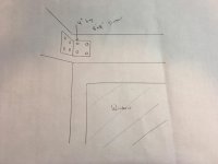
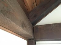
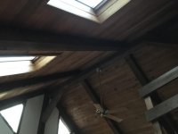
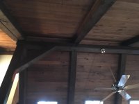
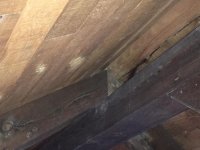
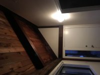
First time poster here. I had a question about support beam bracing. This joint isn't in the best shape (1972 structure) and the doorway adjacent to the joint has tilted somewhat.

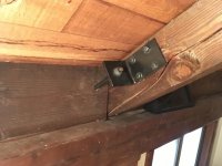
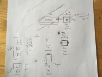
I was thinking of bracing the beam as shown with a Simpson 7x6 Strong Tie.

Any advice would be greatly appreciated.

Thank you,

Kevin
 

Attachments

  • IMG_3156.jpg
    IMG_3156.jpg
    78.5 KB · Views: 260
  • IMG_3130.jpg
    IMG_3130.jpg
    80.8 KB · Views: 408
  • IMG_3155.jpg
    IMG_3155.jpg
    72.6 KB · Views: 367
  • IMG_3157.jpg
    IMG_3157.jpg
    17 KB · Views: 29
To avoid these ads, REGISTER NOW!

wrenchguy

Well-known member
Joined
Sep 22, 2011
Messages
4,697
Location
NW Indiana
that should been a half lap intersection, that way each piece would bear on post. guess u can jack it and pull it and put fix plate on it.
 
OP
K

kvesi122

Member
Joined
Nov 3, 2015
Messages
21
I can try and get a pic of the top to show the joint.

The posts rest on a foundation wall. I think I would need to push the vertical beam upright from the outside and then mount the bracket if I went that route. Anything wrong with bracketing it as is?

Not super concerned with squaring it up perfectly. Just trying to prevent future shifting.
 

why worry

Well-known member
Joined
Oct 3, 2014
Messages
301
I would put the angle brace on the inside corner as you have it shown. I would also use lag screws that would reach at least 3/4 of the way through. Predrill for the size of anchor to minimize the risk of splitting.
 

BD1

Well-known member
Joined
Mar 18, 2007
Messages
4,602
Location
north side
Your angle clip picture is how I did mine except mine was full height.
If you have room on top of the leaning timber you pull that in. Lag screw angle clip on top of that timber and another on the other horizontal . Then use come along, all thread rod, or pipe clamps to draw together. Once set then add angle iron from top of one to top of other. Kinda like a 45 degree angle.
 

Nor'Easter

Well-known member
Joined
Nov 30, 2012
Messages
718
Location
Maine
Timber frames move throughout the year. You can't control nature. I highly doubt you will be able to close that gap, and if you do the checking may may turn into straight grain failure.

It takes one or two 3/8 RSS screws to close an 1/8" gap like that onsite, and this is with green timbers.
 

rsanter

Well-known member
Joined
Dec 22, 2007
Messages
18,505
Location
visalia ca
Highy doubt you will be able to pull that back.
You will need 1/2 steel bracket to begin to counter the force of the warped/twisted piece of lumber
 
OP
K

kvesi122

Member
Joined
Nov 3, 2015
Messages
21
Looks like this turned into a rescue mission.

As far as maintaining stability and integrity, it seems the consensus is to lock it in place with a steel bracket?

**found the original plan for the post setup. Looks like they just used 10" barn spikes to attach the beam to the post from a profile view.
 

Attachments

  • 81B58695-1412-4FB4-844F-DA857C0E2347.jpg
    81B58695-1412-4FB4-844F-DA857C0E2347.jpg
    119.6 KB · Views: 136
Last edited:

matt_i

Well-known member
Joined
Mar 14, 2008
Messages
10,725
Location
SE Michigan
I think you have to be really careful about driving "lags" close to the end-grain (where the timber was cut) as I think it could split out very fast.

What I think I would do is this...make a "heavy metal" strap out of something like 1/4" x 1" flat steel. Could be bent while hot or also welded if you are good with this. Similar to your picture except make the legs 12" long (make from 24" piece of flat bar). Use 4 of the GRK-RSS screws which saw a hole and don't split nearly as bad. I would put 1 of them 3-4" away from the intersection of the corner, and another one ~10" away from the corner on each side.

Now you have it anchored back in the meaty part of the timber as well.
 

lakeroadster

Well-known member
Joined
Jan 19, 2015
Messages
5,166
Location
Central Colorado
There are Post and Beam Connectors that are more up to the task than the Simpson Strong Tie's you're contemplating. As stated above getting away from the end grain is a good idea, and using the GRK screws is also a good choice. Here's a link to some brackets: https://www.houzz.com/product/86474704-tanto-gusset-timber-plate-raw-steel-3-transitional-brackets

attachment.php
 

Attachments

  • kvesi122 Post and Beam.jpg
    kvesi122 Post and Beam.jpg
    49.8 KB · Views: 1,018
OP
K

kvesi122

Member
Joined
Nov 3, 2015
Messages
21
Thank you all for your advice! I'm going to take some measurements so see how much it shifts during the spring months and I'll use a brace similar to the one above if it shifts too much. I'll probably end up welding one up.

Will post up pics of my findings/bracket once that time comes.
 
OP
K

kvesi122

Member
Joined
Nov 3, 2015
Messages
21
Decided to bite the bullet and have a pro come out to assess and estimate repairs. I will post up his findings and suggestions.
 

racingtadpole

Well-known member
Joined
Dec 3, 2011
Messages
2,029
Location
The far side of crazy.. but sometimes Australia
Get up in the roof space and have a look at how the other end of that pitch beam is attached and see if there is anything stopping that one and it’s opposite from spreading. Based on the way that horizontal beam is rolling I would suggest there isn’t. Roof load is being transferred in a downward direction the pitched beams are spreading and taking the horizontal with it. If there isn’t it is probably worth drawing your contractors attention to it because no amount of brackets of refined joinery will stop that movement without stopping the pitches from spreading.

When I first started renovating houses a few moons ago I found this out the hard way..
 

Montyx5

Well-known member
Joined
Mar 5, 2017
Messages
45
Location
Kankakee IL. area
Get up in the roof space and have a look at how the other end of that pitch beam is attached and see if there is anything stopping that one and it’s opposite from spreading. Based on the way that horizontal beam is rolling I would suggest there isn’t. Roof load is being transferred in a downward direction the pitched beams are spreading and taking the horizontal with it. If there isn’t it is probably worth drawing your contractors attention to it because no amount of brackets of refined joinery will stop that movement without stopping the pitches from spreading.

This is what I see as well. It is apparent that this was done by someone without knowledge on this type of construction. I believe that a structural engineer that specializes in this type of repair is required. Without proper supporting and bracing, trying to repair the geometry of the framing members could be catastrophic. It is possible that a situation exsists where one fastener's ability to hold its current load should fail the structure would fail.
 
OP
K

kvesi122

Member
Joined
Nov 3, 2015
Messages
21
The house is built around a ridge beam. The joints at the ridge don't show any signs of shifting but I'll keep looking for the source of movement. The fact that the beams are barely joined has a major effect, I'm sure.

I'm hoping the specialists will be able to pull it together with rods and turnbuckles. Once it's relatively joined, bracket them in place and leave the turnbuckles where possible.
 

R.Anderson

Well-known member
Joined
May 26, 2012
Messages
906
Location
Wisconsin
The house is built around a ridge beam. The joints at the ridge don't show any signs of shifting but I'll keep looking for the source of movement. The fact that the beams are barely joined has a major effect, I'm sure.

I'm hoping the specialists will be able to pull it together with rods and turnbuckles. Once it's relatively joined, bracket them in place and leave the turnbuckles where possible.

Take a look at in the attic. Is there any other bracing to act as/like a bottom chord? I'm willing to guess not. The top chord is not secure to the bottom chord and are spreading as others have stated.

I have seen top chords spoon/bow enough to cause that too, but those were 2x4 chords with not enough bracing.

The spreading is causing the gap and twisting and it is slowly happening over time from the weight of the roof. I'll also second that there is a good chance it is happening else where.

Pulling em back together may cause more problems than it would fix. I would secure em as is.
 
Last edited:
OP
K

kvesi122

Member
Joined
Nov 3, 2015
Messages
21
The house has cathedral ceilings, no attic so it should be fairly easy to hunt around and find more movement. None of the other "joints" show signs of shifting on the other side of the house. Just 2 joints on this side.
 

Montyx5

Well-known member
Joined
Mar 5, 2017
Messages
45
Location
Kankakee IL. area
Something else that has not be mentioned is the state of the foundation. Has there been any settling or movement of the foundation around the problem areas?
 
To avoid these ads, REGISTER NOW!
OP
K

kvesi122

Member
Joined
Nov 3, 2015
Messages
21
The foundation is poured concrete. The wall isn't cracking or bowed at all. Im trying to get access to the foot of the posts to see how they're still squared up on that wall.
 
OP
K

kvesi122

Member
Joined
Nov 3, 2015
Messages
21
Pardon the delayed update. Had a post and beam specialist come out and check the joints along with the original house plans.

They designed 7 custom 3/8" thick brackets that are being installed tomorrow. I will post up pictures of the repairs. The agreed plan was to lock things in place where they would prevent movement and provide the proper structural support without attempting to drastically shift things back into place for aesthetic purposes. As long as they're structurally sound I'm cool with it.

Total cost including the site visit is ~$1100.
 

TLCObsession

Well-known member
Joined
Aug 30, 2011
Messages
328
Location
Bellingham, WA
Do pay attention to the fasteners people have mentioned. I would use RSS or GRKs myself.There is so much wrong with the situation, but tying the beam to the post and the perpendicular beams together should be pretty doable. I wouldn't even try to pull it all the way together, just stabilize it.

If you want an expert engineer to draw you a repair, I can refer you to someone. You may not like what he suggests though.
 
OP
K

kvesi122

Member
Joined
Nov 3, 2015
Messages
21
I'll take some detailed pictures when I get home. I'll also add a few of the general structure and surrounding area.

Drawing up a few turnbuckle/threaded rod designs to see how they could be added tastefully without standing out too much. Will have an engineer come out for the proper installation locations for that as well as a review of the repairs from the post and beam guys.
 
OP
K

kvesi122

Member
Joined
Nov 3, 2015
Messages
21
Do pay attention to the fasteners people have mentioned. I would use RSS or GRKs myself.There is so much wrong with the situation, but tying the beam to the post and the perpendicular beams together should be pretty doable. I wouldn't even try to pull it all the way together, just stabilize it.

If you want an expert engineer to draw you a repair, I can refer you to someone. You may not like what he suggests though.

Why would I not like what he has to suggest? If it's a logical statement from an engineer there isn't much to argue with.
 

lakeroadster

Well-known member
Joined
Jan 19, 2015
Messages
5,166
Location
Central Colorado
Pardon the delayed update. Had a post and beam specialist come out and check the joints along with the original house plans.

They designed 7 custom 3/8" thick brackets that are being installed tomorrow. I will post up pictures of the repairs. The agreed plan was to lock things in place where they would prevent movement and provide the proper structural support without attempting to drastically shift things back into place for aesthetic purposes. As long as they're structurally sound I'm cool with it.

Total cost including the site visit is ~$1100.

Money well spent. Kudos to you for doing this right. :thumbup:
 
OP
K

kvesi122

Member
Joined
Nov 3, 2015
Messages
21
Didn't come out quite as clean as I would have liked but I think they did the best with what they had.

There are 2 of the threaded rod setups installed, 1 on each rafter.

All the water damage occurred in 1998 before the roof was replaced.
 

Attachments

  • IMG_3256.jpg
    IMG_3256.jpg
    88.6 KB · Views: 80
  • IMG_3254.jpg
    IMG_3254.jpg
    119 KB · Views: 78
  • IMG_3253.jpg
    IMG_3253.jpg
    72.7 KB · Views: 71
  • IMG_3252.jpg
    IMG_3252.jpg
    81.2 KB · Views: 81
Last edited:
OP
K

kvesi122

Member
Joined
Nov 3, 2015
Messages
21
More. Showing 1 of the ridge beams. All the joints look fine at the ridge. Confirmed they are joined with straps on the top per the house plans.
 

Attachments

  • IMG_3196.jpg
    IMG_3196.jpg
    78.6 KB · Views: 50
  • IMG_3197.jpg
    IMG_3197.jpg
    97 KB · Views: 51
  • IMG_3199.jpg
    IMG_3199.jpg
    93.5 KB · Views: 49
  • IMG_3200.jpg
    IMG_3200.jpg
    130.9 KB · Views: 46
OP
K

kvesi122

Member
Joined
Nov 3, 2015
Messages
21
And one last one showing the 2 shorter rafters that the threaded rods were lagged to.

The furthest one is along the outer wall.

Fire away if you disagree with this repair. I'm curious to hear what the different opinions are so I can learn from this either way, at the very least.

**Don't know why this attached sideways unless it's the resolution**
 

Attachments

  • IMG_3261.jpg
    IMG_3261.jpg
    79.6 KB · Views: 34

lakeroadster

Well-known member
Joined
Jan 19, 2015
Messages
5,166
Location
Central Colorado
Seems like they should have made this bracket as a welded fabrication in order for it to fit tight against the beam... or made a filler piece...

attachment.php
 

Attachments

  • kvesi122.jpg
    kvesi122.jpg
    119 KB · Views: 193
OP
K

kvesi122

Member
Joined
Nov 3, 2015
Messages
21
I suppose I could add a filler piece, but if they angled the tab to be flush against the foot it would only be bearing the edge of the nut and washer rather than the full contact surface. I agree with what they did, although the spacing is a little excessive.
 

BD1

Well-known member
Joined
Mar 18, 2007
Messages
4,602
Location
north side
Seems like they should have made this bracket as a welded fabrication in order for it to fit tight against the beam... or made a filler piece...

attachment.php

Yes I agree. They did it the easy way. Cut a piece of angle iron and drilled holes.
 
OP
K

kvesi122

Member
Joined
Nov 3, 2015
Messages
21
A welded bracket (assuming it was welded properly) would be stronger I'd think but this is up about 12-14ft so it blends in.

As long as it serves its purpose structurally I'm happy.
 

Ole Slewfoot

Well-known member
Joined
Feb 22, 2016
Messages
5,098
Location
Freedom, CA
Unless im mistaken its just tied to a soffit block...
RSS fasteners wold serve better than lags, through bolts even better.
I don't think that would pass any inspection in CA, but we have our unique challenges that may not affect you.
We have to put a 90* twist strong tie on every rafter.
 
OP
K

kvesi122

Member
Joined
Nov 3, 2015
Messages
21
The threaded rod is attached to this bracket on the other side of the soffit block:

attachment.php


The rafter is a 2 piece setup that is toenailed to the beam. Not the way I would have built the house but I'm making do with what I have.

Through bolts would have been nice, I agree. 6" square head lags were used. The backside of the bottom portion is not accessible without tearing off siding. I thought about using a hole saw to zip a plug out and through bolt.

The brackets preventing further spreading/slipping of the 2 rafters that are toenailed to the rafter tie. Feel free to thump me on the head if this is the incorrect nomenclature.
 
Last edited:
OP
K

kvesi122

Member
Joined
Nov 3, 2015
Messages
21
No problem!

You guys are all a hell of a lot smarter than I am, not trying to argue with your responses.
 
OP
K

kvesi122

Member
Joined
Nov 3, 2015
Messages
21
Had a structural engineer come out to check out the remaining rafters. He recommended a turnbuckle system in addition to what is currently in place. 2 in the living room area and one in the 2nd floor sleeping area that has a center post.

This is the design that I came up with based off of his quick bracket sketch. Shot it over to him for his approval. If he deems it sufficient I will likely have a crew recommended by him install it.
 

Attachments

  • IMG_3304.jpg
    IMG_3304.jpg
    104.3 KB · Views: 33
To avoid these ads, REGISTER NOW!
Top Bottom