To avoid these ads, REGISTER NOW!

Power supply discussion

skeer

Well-known member
Joined
Sep 14, 2021
Messages
1,049
Location
Standish, MI Area
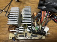
I wanted to create this thread both to help me keep track of stuff and to hopefully ask some questions and learn more. I pulled an older atx psu from an HP desktop I have out in storage, it's rated for 440w and the base board is a Delta, DPS-460DP-5. I have not been able to locate any schematics on this model but it does have a separate rectifier board pre-transformer(s).

I have not been able to look or test much with this yet but I did verify post rectification circuits output is 120-ish VDC, and interestingly enough the primary input for the large transformer on the second board measured around 215VDC.
I'd love to find the schematic for this, not that I'm smart enough to re-engineer things but curiosity is a b~tch. This has spurned a couple new thoughts that, I'll share here. From what I have read, there's many variables to define before you could answer the question; rectify before or after transformer. I'm pretty sure in this case either is just as good.

The other thought bouncing around is, I'm still looking for a way to adjust the output voltage to my terminals. So there's either - A; a rotary switch between 3, 5, and 12. Or B; a variac, pot, or an SCR?
Vary & regulate the AC input voltage or the DC output voltage? Of course neither of those address the desire for more than 12 volts either.. so there's still that as well.IMG_0140.jpegIMG_0138.jpeg
 
To avoid these ads, REGISTER NOW!

dogdog

Well-known member
Joined
Nov 15, 2011
Messages
12,711
There are no transformers on these SMPS... what you are seeing are either Inductors , Chokes or common mode Chokes for RFI filtering... and the rest are DC to DC buck converters. Sorry got the Adult ADHD so never learned SMPS properly hope some one can help, just pointing out so you don't go down the wrong path.


theoldwizard1

Well-known member
Joined
Feb 22, 2011
Messages
43,466
Location
SE MI
Dogdog is correct. Almost all DC power supplies built on the past 30 (or more) are Switch Mode Power Supplies (SMPS). There is lots of documentation on how these work. There is usually just one IC that controls the whole thing (maybe more on an ATX power supply because it creates 3 voltages: +12, +5 and +3). The incoming AC is rectified to DC. This would probably be a very "bumpy" (unfiltered) DC close to 200V.

This is passed to the "switcher IC" power transistors. They are turn on/off at high frequency (40kHz or more). These "charge" the inductors. Some filtering and most important a feed back loop to the switcher to control the pulse width modulation (PWM).
 

theoldwizard1

Well-known member
Joined
Feb 22, 2011
Messages
43,466
Location
SE MI
You will NEVER be able to convert that into a fully adjustable power supply !

Just mount it in a plastic box with 1 blank banana jack (ground) and 3 red banana jacks (+3, +5 and +12). The +5 has the most power capability. One of the other wires needs to be shorted to ground to turn it on.

There are after market kits/plans to turn that into a fully adjustable power supply.

If you wandt more power, buy a used Dell DA-2 power brick. 12V @ 18A !
 

SlappyWhite

Well-known member
Joined
Oct 3, 2012
Messages
1,819
Location
Upper Canada
As others noted it is a switching power supply....

I believe the input is rectified (full wave bridge) so if you are putting 120VAC (technically 120v RMS, ~170 v peak...) into it you will measure 240 to 340 VDC (depends on some factors and the meter). Why you are likely seeing the 215 VDC at some point deeper in.

No way to easily make it adjustable output as is but you can always add an adjustable regulator on the DC outputs.
 
To avoid these ads, REGISTER NOW!

dogdog

Well-known member
Joined
Nov 15, 2011
Messages
12,711
As others noted it is a switching power supply....

I believe the input is rectified (full wave bridge) so if you are putting 120VAC (technically 120v RMS, ~170 v peak...) into it you will measure 240 to 340 VDC (depends on some factors and the meter). Why you are likely seeing the 215 VDC at some point deeper in.

No way to easily make it adjustable output as is but you can always add an adjustable regulator on the DC outputs.
Only one problem… dc regulator at that high of voltage spec is going to cost $$$$$$.
 

MBfreak

MEMBER EMERITUS
Joined
Dec 10, 2010
Messages
2,301
Location
Linkoping , Sweden
Quote
There are no transformers on these SMPS.
Unquote
Wrong

There are no POWER FREQUENCY transformers on switch mode power supplies.
HOWEVER
There is a high frequency transformer, sometimes with several windings. in all switch mode power supplies that are used to run computers, amplifiers etc.
This to isolate the driven parts neutral ( ie chassis)from mains voltage to earth.
Sealed units like LED lamps etc have most often just an inductor.

Ola
 

Chukster

Well-known member
Joined
Jan 25, 2012
Messages
2,599
Location
Cary, NC
Well, switching power supplies are really quite complex things. Not generally something for a beginner to tackle. Lots of sensing and feedback of signals to control circuits, etc. You will learn in the process, but i predict it will be slow. And yes, many of the voltages on the circuit board are quite high. Technician beware, just like the olden days of vacuum tubes with 100, 200, 300 & more Vdc power supplies.
 
To avoid these ads, REGISTER NOW!
Top Bottom