f150skidoo
Well-known member
I have been wanting to improve my bending capability's in the shop for awhile. My 32" brake in my shop press and 4 foot box and pan brake ain't cutting it anymore, always need wider then the shop press and thicker then the box and pan brake. I've been looking at the classified's and auctions for over a year and haven't found one that fits my needs.
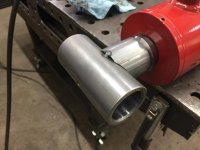
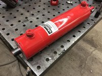
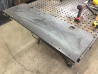
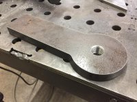
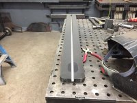
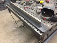
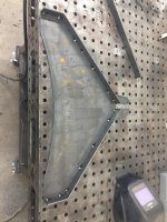
So I decided to just build one. My brake is going to based off of the DXF files from BESRK's build on Pirate4x4 but I significantly changed them to add more strength and to be more compact of a machine. After I figured out the basic design I constructed a 3D rendering then ran stress simulations to make sure the frame was up to the task. This style of brake uses mechanical advantage, so with the 3.81:1 ratio a 3.5" bore cylinder @3000psi will create 110,049 lbs of force. But I'm going to reduce the pumps psi to drop the machines tonnage to 44-45 tons. I outsourced the cutting of the 1" plate frame which was ready for pickup today and I also picked up a 3hp power unit.
So I decided to just build one. My brake is going to based off of the DXF files from BESRK's build on Pirate4x4 but I significantly changed them to add more strength and to be more compact of a machine. After I figured out the basic design I constructed a 3D rendering then ran stress simulations to make sure the frame was up to the task. This style of brake uses mechanical advantage, so with the 3.81:1 ratio a 3.5" bore cylinder @3000psi will create 110,049 lbs of force. But I'm going to reduce the pumps psi to drop the machines tonnage to 44-45 tons. I outsourced the cutting of the 1" plate frame which was ready for pickup today and I also picked up a 3hp power unit.


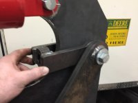
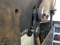
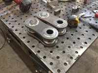
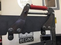
 And over-center linkages can REALLY increase the forces as they pivot.


") ....I have on my list to work on my Diacro, it slowly leaks from the tank to the point where the pump aerates the fluid...
....I have on my list to work on my Diacro, it slowly leaks from the tank to the point where the pump aerates the fluid...