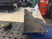
I used 3/4" 85 degree die since it's my smallest full width die on my 4way die. My 5/8 and 1/2" dies are all short lengths. My punch has a .125" radius. I wasn't trying to over bend it, but I think that happened since I was using a die 50% to large for the material. I didn't try coining it.
Gotcha. The 1/8R Punch should work well using a 1/2" Bottom on .060. We typically figure 4-5-6 times material thickness for the opening using a .008, .016 or .031R. Anything bigger we add the additional Punch Radius minus 1/32. That gets us close enough to work out the details if we have to hold +/-.005 which is becoming more and more common in a world where designers and engineers default their Cad Systems to 3 place decimals...and it is an act of Congress to get them to use a tolerance scheme that makes sense.
85° Tooling will require Air Bending. Coin it and you will be over 90° assuming you have matching Punch angles.
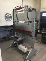
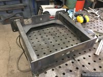
Nice job on the Machine!!!
We are experimenting with 86° Tooling for our ATC (Automatic Tool Change) Brakes. Using this tooling allows for the machine to get feedback and adjust the depth of stroke to hold angles on varying material thickness.
The drawback to Air Bending is the Form bulges at each end of the bend. Causes issues at weld assembly and inspection has issues with a part where the flange will check in print except where there is a bulge, they check big or out of print in some cases. Need to do some serious soul searching on this change if we decide to move forward. It is +/-$100K per machine to change out the tooling. But set-up time is reduced. Not sure if it is enough for an ROI.
I am really interested in seeing the data you collect.


")