To avoid these ads, REGISTER NOW!

Press Brake Die Holder

jimgood

Well-known member
Joined
Aug 4, 2014
Messages
2,394
Location
Marshall, VA
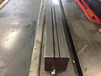
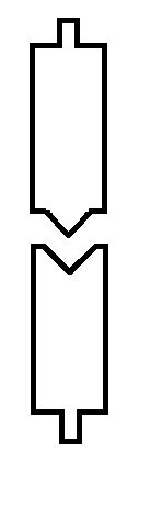
I'm new to press brakes but I have a rudimentary understanding of how they work. I ordered a set of press brake dies but I will need a holder. I'll be using these in my HF 20-ton press to bend 1/8" sheet so pretty light duty. The profile of my dies looks like the crude diagram below. The tab along the spine of the die is exactly .5" wide by about .63 tall. The dies are 5" long.

I have looked around online but I'm not well versed in the terminology and I'm not sure what to search for. I'd like to keep the cost under or around $100. Can anyone help me find what I'm looking for? I'd like to at least get an idea of cost to see if my fallback plan is more or less reasonable.

My fallback plan:
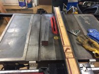
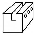
Was to get a piece of 2 x 2 steel 10" long and having about a .515" by .75" deep channel cut down the middle the full length. I'll cut it in two pieces about 5" long, one for the bottom and one for the top.

On the top one, I'll drill and tap holes for set screws through one side of the channel. The idea is that the tab on the die would fit into the channel and be held in place by tightening the set screws. I would weld a collar on the top of the holder to fit around the tube under the top of the press, also with a set screw.

I think my steel supplier is doing machine work now so I'll see what they'd charge for cutting the channel. I might also check with a local machine shop.

Edit: I just realized that I made a slight error in my diagram below. The top die (punch) will not have shoulders where it meets the bottom die. The "vee" will go all the way to the edges.
 

Attachments

  • Untitled.jpg
    Untitled.jpg
    8.4 KB · Views: 46
Last edited:
To avoid these ads, REGISTER NOW!
OP
J

jimgood

Well-known member
Joined
Aug 4, 2014
Messages
2,394
Location
Marshall, VA
That's great. Was there a specific term you used to search for the specific profile for your dies? Are they all the same?
 

ez-duzit

Well-known member
Joined
Jun 24, 2013
Messages
5,094
Location
Marina del Rey
That is a standard size/shape. But I wouldn't say they're all the same. Double-check the dimensions.

BTW, for my bottom die I found a new drop off a 3-3/4" (square) 4-way die.

brake-dies_zpsc3a199bd.jpg
 

4 FN 27

ALLIANCE MEMBER
Joined
Oct 19, 2015
Messages
4,635
Location
Minnesnowta
That's great. Was there a specific term you used to search for the specific profile for your dies? Are they all the same?

Press Brake American Die Holder

Press Brake American Die Adaptor

I am assuming you have "American Tooling" coming? From your description it is an American Tang on the tooling.

If you are looking to adapt something you could try:

http://www.gladwinmachinery.com/

Call them and ask for Joe Miska.

They have all kinds of stuff used. You pay by the pound and they will ship it.
 
Last edited:

gorilla

Well-known member
Joined
Dec 13, 2007
Messages
1,649
If you plan on using this die setup on a HF press you don't need die holders. Just cut the tab off the bottom die and adapt a piece of round tube to the top die for the press ram.We had a requirement to bend 2" wide 1/2" plate 90* now and then it was too much trouble to change dies in the pressbrake for one or two bends so we would do it in the shop press with a setup like what your talking about.
 
OP
J

jimgood

Well-known member
Joined
Aug 4, 2014
Messages
2,394
Location
Marshall, VA
Press Brake American Die Holder

Press Brake American Die Adaptor

I am assuming you have "American Tooling" coming? From your description it is an American Tang on the tooling.

If you are looking to adapt something you could try:

http://www.gladwinmachinery.com/

Call them and ask for Joe Miska.

They have all kinds of stuff used. You pay by the pound and they will ship it.

That was helpful. Thanks.
I guess what I'm really looking for is a punch holder. I actually don't know what the punch looks like yet. When the seller sent the punch and die, the box broke open in shipping and the **** heads at USPS taped the box up with only the die in it. I thought the punch would look similar to the die. I'm still waiting on it.

My diagram of the bottom die is accurate. I'm not so concerned with that as I am with how to hang the punch from the press.

The punch holders on that site above look kind of involved so I better wait and see what my actual punch is going to look like before I get to far ahead of myself.

gorilla, I guess I could weld a collar directly to the top of the punch but it's going depend on its shape.

It seems to me like the die could just sit with the tang between two plates.

I have looked at the Swag Offroad stuff and I probably could have just done that if I'd had my head screwed on straight.
 

ez-duzit

Well-known member
Joined
Jun 24, 2013
Messages
5,094
Location
Marina del Rey
I am going to use extension springs to suspend the top die and holder, keeping them pressed tightly against the ram of my 50-ton Carolina press.
 
OP
J

jimgood

Well-known member
Joined
Aug 4, 2014
Messages
2,394
Location
Marshall, VA
Revisiting this thread because I have an update or two.

I received the punch and it is exactly like the one pictured in ez-duzit's post, just shorter.

To make a pair of holders, I ordered two pieces of 10 x 2" 1018 square bar ($108 w/ shipping) and a couple of 7 1/4" metal cutting circ saw blades ($41.50 w/ shipping). Tomorrow I'm going to pick up a cheap second hand Skilsaw ($30).

The plan is to use the saw to cut grooves into the square bars that will receive the tangs on the punch and die. Then I'll drill and tap them along the sides of the grooves for set screws.

For the punch, I'll source a piece of round tube and weld it to the top of one of the holders. This has to be 1 5/8" ID with a little clearance. I could order something from onlinemetals but the minimum will be a 10-12" piece and it will run over $40 with shipping. I only need a piece about 2" long. I'll see if I can find something at the scrap yard or maybe a cut off at the local machine shop. Another option will be to get a 3/16" x 2" flat bar and forge it around the shaft on the HF press.

The two major unknowns with my plan are:
  1. How the blades will hold up cutting 3/4" deep into 2" steel. I'm thinking I should make several passes getting gradually deeper each time.
  2. Will the sides be smooth enough and true enough that the punch/die won't tilt when the set screws are tightened. That's going to come down to how well I can jig this so that the cut's are repeatable and how tight I can keep the saw against the guide. So my fallback plan is to just permanently weld the punch/die into their respective holders. Shouldn't need more than tack welds at each end and the most important orientation is the mating surface of the shoulders of the punch/die on flat of the bars.


For the record, I priced having a local machine shop mill grooves into two pieces of A36 and it was going to run close to $500 (their price on the stock was the same as me ordering and having it shipped). Granted, I spec'd two 22" pieces but the metal was $160 and the rest was labor. This guy is really busy and he doesn't need my piddling job so :dunno:
 

Attachments

  • Untitled.jpg
    Untitled.jpg
    14.4 KB · Views: 28
OP
J

jimgood

Well-known member
Joined
Aug 4, 2014
Messages
2,394
Location
Marshall, VA
I could use some help on this.

I have two 2" square bars 11" long in 1018 steel. Per my post above, I decided to use a metal cutting saw to cut the grooves. I ordered two 7 1/4" blades as I was planning to use a cheap Skil saw. But now I'm wondering if I should use my table saw. It would be infinitely easier to keep the parts running straight on the table saw.

The Skill saw blades have a max speed rating of 7430 rpm. My table saw runs at 3450 but uses a 10" blade. Both blades have the same arbor size and I only need the little blades to be above the table by a max of 3/4" so I think that will work.

If I'm calculating it correctly, the circumference of the blade is just shy of 22.8" or 1.9 feet. So, using the table saw, that should be a cutting speed of 6555 FPS (circumference * RPM). EDIT: this is definitely wrong. I think it should be 6555 FPM or 109.25 FPS.

Regardless of whether my calculation is correct, we know that's going to be about half the speed that the blade was designed for. The question is, is that too slow?
 
Last edited:

astroracer

Well-known member
Joined
Jun 22, 2005
Messages
3,001
Location
Mid_Michigan
How wide is the groove? 3/4"? Order a piece of steel 1 1/4" wide at that thickness x 22" long.
Order two more pieces the same thickness only 2" wide. Drill and C'bore one for 1/2" SHCS's. Drill and tap the other and drill thru holes on the narrow piece. Clamp them together with the bolts. Viola! A die holder. :)
Mark
 

racingtadpole

Well-known member
Joined
Dec 3, 2011
Messages
2,029
Location
The far side of crazy.. but sometimes Australia
I could use some help on this.

I have two 2" square bars 11" long in 1018 steel. Per my post above, I decided to use a metal cutting saw to cut the grooves. I ordered two 7 1/4" blades as I was planning to use a cheap Skil saw. But now I'm wondering if I should use my table saw. It would be infinitely easier to keep the parts running straight on the table saw.

The Skill saw blades have a max speed rating of 7430 rpm. My table saw runs at 3450 but uses a 10" blade. Both blades have the same arbor size and I only need the little blades to be above the table by a max of 3/4" so I think that will work.

If I'm calculating it correctly, the circumference of the blade is just shy of 22.8" or 1.9 feet. So, using the table saw, that should be a cutting speed of 6555 FPS (circumference * RPM). EDIT: this is definitely wrong. I think it should be 6555 FPM or 109.25 FPS.

Regardless of whether my calculation is correct, we know that's going to be about half the speed that the blade was designed for. The question is, is that too slow?

The idea of using a hand held saw is at best marginal, and using a table saw is just plain dangerous. You are attempting a milling operation, please consider spending the small amount of money it would cost to have a machine shop profile out the steel safely on a machine that is designed for that purpose.

If you are being quoted $500 to supply and mill those two pieces of steel, look around elsewhere.
 
Last edited:
OP
J

jimgood

Well-known member
Joined
Aug 4, 2014
Messages
2,394
Location
Marshall, VA
How wide is the groove? 3/4"? Order a piece of steel 1 1/4" wide at that thickness x 22" long.
Order two more pieces the same thickness only 2" wide. Drill and C'bore one for 1/2" SHCS's. Drill and tap the other and drill thru holes on the narrow piece. Clamp them together with the bolts. Viola! A die holder. :)
Mark
The groove will need to be a nominal 1/2" wide by 3/4" deep. It needs clearance for a slip fit.

I don't know what SHCS is.

But I guess I could have tried something like this. I wish I had thought of this before I paid $120 for two hunks of square bar :lol_hitti:
attachment.php
 

Attachments

  • Untitled.jpg
    Untitled.jpg
    13.4 KB · Views: 735
OP
J

jimgood

Well-known member
Joined
Aug 4, 2014
Messages
2,394
Location
Marshall, VA
The idea of using a hand held saw is at best marginal, and using a table saw is just plain dangerous. You are attempting a milling operation, please consider spending the small amount of money it would cost to have a machine shop profile out the steel safely on a machine that is designed for that purpose.

If you are being quoted $500 to supply and mill those two pieces of steel, look around elsewhere.
Why would cutting steel on a table saw be any more dangerous than cutting wood? Not trying to be a smart ***. I really want to know what risks you're seeing that I'm not seeing.
 

racingtadpole

Well-known member
Joined
Dec 3, 2011
Messages
2,029
Location
The far side of crazy.. but sometimes Australia
Think about the forces involved..


In that video the cut is all the way through, you want to make a cut that wont go full thickness. It is more than probable that the blade will become bound up by the chips and you will have an 11" long missile of 2" square stock.
 
Last edited:

OccupantRJ

Well-known member
Joined
May 15, 2009
Messages
10,906
Location
Eastern North Carolina
I think you are going to learn a valuable, dangerous lesson. On a horizontal mill designed for that type of work, and using coolant, about 200 rpm on a 4" diameter cutter will tremble a 3,500 lb machine. My Spidey senses are screaming no. I feel the blade will get hot and take on a wavy shape at a minimum, then the problems really begin. I am usually not the naysayer type, so film this for posterity and to prove me wrong. My experience is 28 years designing tooling setups for milling machines for production work. My wife says that I am always wrong.
 
To avoid these ads, REGISTER NOW!

skipnay

Well-known member
Joined
Dec 11, 2014
Messages
600
Location
PA
Seriously?
What's your hobby then, stamp collecting?
:supergay:

I'm around loud equipment like rollers, pavers, loaders, traffic, and so on all day long. My ears just can't take certain noises anymore!!!
 

4 FN 27

ALLIANCE MEMBER
Joined
Oct 19, 2015
Messages
4,635
Location
Minnesnowta
Go to Wilson Tool and down load their catalog. They have all kinds of holders and how to place the tools in them and where the load goes. This should give you some solid ideas of how to build a safe holder.

The pic of the 3 piece assembly is ok but the pressure should be on the tang. Not the rails.
 

Mario428

Well-known member
Joined
Dec 4, 2009
Messages
156
Location
PEI, Canada
The pic of the 3 piece assembly is ok but the pressure should be on the tang. Not the rails.

Have done a lot of press brake work and every die holder I have seen uses the tang to locate and clamp, is never used to put pressure on the die.
 

4 FN 27

ALLIANCE MEMBER
Joined
Oct 19, 2015
Messages
4,635
Location
Minnesnowta
Have done a lot of press brake work and every die holder I have seen uses the tang to locate and clamp, is never used to put pressure on the die.

100% agree if you are using a 2 piece holder. Not a 3 piece. Side load that a little and you will have parts flying.
 
OP
J

jimgood

Well-known member
Joined
Aug 4, 2014
Messages
2,394
Location
Marshall, VA
Well, after all this safety discussion, I went down in the shop set up the table saw and took two passes in 1/8" increments. It cut like butter.

There's not enough energy in the saw to do much with the inertia of 12 lb piece of steel.

I had to stop because the motor pulley came off. No, it didn't shear the pin. It just backed off. It does this sometimes and I forgot to check it before I started.

I got it all back together and as far as I can tell, this is a perfectly workable solution that is going to cost me $18 instead of a $90+/hr shop rate for someone to set up a milling machine and make the same cut.
 
OP
J

jimgood

Well-known member
Joined
Aug 4, 2014
Messages
2,394
Location
Marshall, VA
Ok. I'm admitting defeat. Not for safety reasons but for the fact that the blades can't hold up to the heat generated by being enclosed in the kerf. I tried to feed the work very slowly but I don't think it mattered. Slower feed probably just means the heat has more time to build and soak into the blade.

I also ran into another issue. I made two passes on one side then turned the piece to work on the other side. The fence moved a little during the cut and it veered off by a few thousanths on one end. That also caused the blade to heat up quicker. I clamped the fence better but by that time the blade was too far gone.
 

Attachments

  • IMG_2192.JPG
    IMG_2192.JPG
    112.5 KB · Views: 81
  • IMG_2191.JPG
    IMG_2191.JPG
    140.4 KB · Views: 75
Last edited:

jamscal

Active member
Joined
Jan 22, 2016
Messages
36
Location
Louisville, KY
IMAG0341.jpg


My punch holder, worked fine, upgraded to 1/2x6 cold rolled steel in a later version.

2pcs of 3" channel with a piece of square stock welded in...1/2" bolts pinch the punch.

IMAG0342.jpg
 

OccupantRJ

Well-known member
Joined
May 15, 2009
Messages
10,906
Location
Eastern North Carolina
Ok. I'm admitting defeat. Not for safety reasons but for the fact that the blades can't hold up to the heat generated by being enclosed in the kerf. I tried to feed the work very slowly but I don't think it mattered. Slower feed probably just means the heat has more time to build and soak into the blade.

I also ran into another issue. I made two passes on one side then turned the piece to work on the other side. The fence moved a little during the cut and it veered off by a few thousanths on one end. That also caused the blade to heat up quicker. I clamped the fence better but by that time the blade was too far gone.

If the slot width is still ok, it can still be milled out with a milling machine. A vertical mill will work, but just be slower. Why don't you see if there is a GJ member on here local to you who has a mill and wants to make a few bucks?

Also, check the piece for straightness since your operation. Long pieces often tend to stress relieve and develop a crown after removing material on one side. This machining endeavor can be more devious than first meets the eye.
 
Last edited:

Muggzy

Well-known member
Joined
Jun 29, 2013
Messages
583
Location
Orange Co., NY
Hi there! Is there a strong reason to prepare everything from the zero if there are available units to purchase to install for standard garage presses, for example...
http://www.edwardsironworkers-latino.com/accesorio-para-doblar.html
Yeah! Like the challenge & satisfaction of making your own tool to do the same job for a fraction of the price. While that line of "garage presses" in your link are beautifully made, I can think of a lot of things to do with that kind of money [emoji2]

Sent from my SM-G920V using Tapatalk
 
To avoid these ads, REGISTER NOW!
Top Bottom