To avoid these ads, REGISTER NOW!

Probably an easy question regarding current through a simple circuit...

Danguitarman

Well-known member
Joined
Nov 3, 2013
Messages
180
Location
Twin Cities, MN
I've become very interested in electronics. I bought a few breadboards and some components to mess around with. I have been building some simple circuits, and although I believe I have a steady grasp on the wiring part, I have encountered an anomaly that I cannot quite explain.

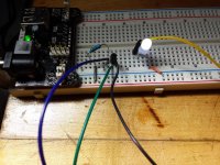
I've built a simple circuit with a 220 ohm resistor, a 10k potentiometer and an led on a breadboard. I just want to know why, when I cut into the circuit to measure amperage, the milliamp reading spikes to 1.92ma as I'm opening up the pot, but then falls to basically nothing. The led still maintains high brightness, even as the milliamp reading drops like a stone, and then it settles out at 0.01ma. Why is it not giving a constant reading of what the led should be drawing?

The led is first in the circuit, followed by the pot, then my meter, then the resistor and on to ground. I know this will come as second nature to many of you, but I've looked through my books, and I cannot find a reason for this. Thanks!
 
To avoid these ads, REGISTER NOW!
OP
D

Danguitarman

Well-known member
Joined
Nov 3, 2013
Messages
180
Location
Twin Cities, MN
No. It goes straight through my meter. I tried to upload a damned good photo of the actual circuit, but it was too many pixels for the website, I guess. Sorry
 

walta

Well-known member
Joined
Jan 13, 2017
Messages
2,307
Location
Dutzow Missouri
My guess is you are using a digital meter that is slow to react to the change in current flow.

Walta
 

BillK

Well-known member
Joined
Aug 24, 2006
Messages
9,297
Location
Beautiful Southern Maryland
When you say it "spikes" do you mean no matter where you turn the pot to the current spikes high then settles to the same number ? Or do you mean that as you turn the pot the current starts high then goes lower as you turn the pot ?
 
OP
D

Danguitarman

Well-known member
Joined
Nov 3, 2013
Messages
180
Location
Twin Cities, MN
When you say it "spikes" do you mean no matter where you turn the pot to the current spikes high then settles to the same number ? Or do you mean that as you turn the pot the current starts high then goes lower as you turn the pot ?

The numbers ramp up VERY quickly as I am turning up the pot. However, if I let off the potentiometer the numbers immediately start going down. Very quickly at first, then they just sort of "trickle" down to essentially nothing. The led does not drop in brightness, however.
 

ripperd

Well-known member
Joined
Jul 2, 2014
Messages
2,041
Location
Twin Cities, MN
what power source are you using? can you show a schematic, and test points where your probes would be?

Some potentiometers are pretty nonlinear as well. When the pot gets to 10k, the LED should be pretty much out unless your wiring is not perfectly in a series.

Edit: also show what breadboard you are using and where everything is connected on it. Sometimes the internal connections on breadboards are not intuitive.
 

walta

Well-known member
Joined
Jan 13, 2017
Messages
2,307
Location
Dutzow Missouri
My meter is a Fluke 87V

I own an 87 it is a great meter but it is not fast.

You cannot believe numerical reading that is not stable for several seconds, for faster changing inputs try looking at the bar graph across the bottom of the screen.

If the Led under test happens to be white or yellow, they use a phosphor coating that glows for some time after the current stops.

Walta
 

BillK

Well-known member
Joined
Aug 24, 2006
Messages
9,297
Location
Beautiful Southern Maryland
I let off the potentiometer the numbers immediately start going down.

What do you mean by "letting off" ? Turning it back down ?

Like the others asked, what are you powering it with (how many volts) and do you have a part number for the led ? I have a feeling what you are seeing is normal but without knowing the entire circuit its hard to tell for sure. This is how I am envisioning your circuit:
 

Attachments

  • pot.jpg
    pot.jpg
    68.6 KB · Views: 185

MBfreak

MEMBER EMERITUS
Joined
Dec 10, 2010
Messages
2,301
Location
Linkoping , Sweden
Please post a sketch showing circuit, including power supply and its nominal voltage, ammeter, 220 Ohm pot and LED. We also need to know the type of LED, since they have quite different forward voltages.
What I can understand from OP, there must be an anomaly in the description.
If current thru the LED is as low as stated , the LED will be off.
What range of the Fluke 87 V have you selected? I guess it is on 300 mA setting and on common and mA/microA sockets.

Ola
 

ransil

Well-known member
Joined
Jul 22, 2018
Messages
313
Location
pa
Connect the open end pot the pot to the wiper terminal

Sent from my SM-G920V using Tapatalk
 
OP
D

Danguitarman

Well-known member
Joined
Nov 3, 2013
Messages
180
Location
Twin Cities, MN
Ok, so I finally figured out the photo thing. Here is the circuit. Blue and green wires go to the pot. Yellow and black go to my meter. The power source provides 5v. I have it hooked up to the mains by way of a 12v /2.5a power brick. How many amps the breadboard supply chip will actually provide... I'm not sure.

When I said the amps drop like a stone as I "let off" the pot, I meant that I have just stopped turning it up or down. The result seems to be the same no matter where I leave the knob in its range of travel. I have the meter probes hooked up and set for mA/A. Hope this helps.
 

Attachments

  • 20190103_172717-1305x979.jpg
    20190103_172717-1305x979.jpg
    147.7 KB · Views: 56
To avoid these ads, REGISTER NOW!

theoldwizard1

Well-known member
Joined
Feb 22, 2011
Messages
43,073
Location
SE MI
If BillK's drawing is accurate ...

attachment.php


... then you should NOT "cut into the circuit".

First, verify the voltage into the circuit with you meter.

Second MEASURE THE VOLTAGE DROP ACROSS THE 220 OHM RESISTOR. Use Ohm's Law I = V/R (current through a fixed resistor is equal to the voltage drop across the resistor divided by the value of the resistor).


This is the PREFERRED way of measuring current. (Not only is it the preferred way, this in fact how current is measured in all ammeters !)

You never really want to cut into a circuit to measure current. If your meter is set to the INCORRECT RANGE you will damage the meter.
 

BillK

Well-known member
Joined
Aug 24, 2006
Messages
9,297
Location
Beautiful Southern Maryland
So this is what you should have. Without knowing the led specs it is impossible to tell you what the current should be.

Like "old" said, it is usually not a good idea to put a meter inline like you have it unless you are absolutely positive that the current in the circuit will never be greater than what the meter can handle without damage. I imagine most modern meters have overcurrent protection but it is still not the best practice.

If you want to try something take the led out of the circuit, jut short across it. With the pot at full resistance (10k ohms) you should have about .00049 amps which is .5 ma ? almost nothing. With the pot completely in the other direction ( 0 ohms) you should have about 22 ma.

The current should change between those two figures as you turn the pot from one end to the other.

I just thought about something else too ...... how do you have the pot hooked up ???? Should be from the center lug to one of the end ones.
 

Attachments

  • circuit.jpg
    circuit.jpg
    139 KB · Views: 20

MBfreak

MEMBER EMERITUS
Joined
Dec 10, 2010
Messages
2,301
Location
Linkoping , Sweden
Looking at the breadboard with explanations the wiring from the lower power +rail thru the resistor 220 , and then to the b/g wires thru the pot to the black wire (+ on mA meter)and back in the yellow wire from the mA meter to the anode of the LED with the cathode to the minus rail seems correct.

WRT to this comment in the thread, Not only is it the preferred way, this in fact how current is measured in all ammeters !)
I think it can be disregarded . There are ammeters based on direct measurement of the magnetic field, and there is absolutely nothing wrong with connecting a Fluke 87 V set to mA in a circuit that will at most have a 22 mA( 5/220 A) current thru it.
And the renewal rate in a fluke 87V numbers display is 250 ms and the bar graph is 25 ms. Forget about slow sampling screwing the experiment up.
So, I believe your intentions and wiring is correct.
The first thing you may be interested in now is that the light intensity /current tru a (modern) LED is very unlinear.
The second is that you just short circuit the LED and observe the relationship between the setting on the 10 K pot and the ammeter. Taking for granted that the pot is OK and that the power rails are really 5,0 V DC you need to read the following current values
Pot set at 10 KOhms, I= 5/10000A=0,5 mA ( The R of the FLUKE may lower this some)
Pot set at 0 Ohms I = 5/220=22 mA.
Current values may be a bit off due to tolerances.
When you turn the pot between 10K and 0 the mA shall follow smoothly if it is linear pot, otherwise in a log pattern compared to turning angle.
Wild guess is that you have a iffy 5 V or that your FLUKE have had some unhappy experiences on the current rating . Check it
And be sure that your FLUKE is set to mA DC range, selectable between AC and DC with ine of the rectangular buttons.

Ohms Law is non-negotiable!

Ola
 
OP
D

Danguitarman

Well-known member
Joined
Nov 3, 2013
Messages
180
Location
Twin Cities, MN
Guys, thanks very much for taking the time to respond to my questions with great advice! I will now admit, the problem was me all along... I just recently got into electronics, and although I have had some formal education in electrical wiring and ohm's law and such from when I went to college for a diesel mechanical degree, it was a long time ago, and I have only done simple wiring troubleshooting and stuff since then. I have since switched careers.

I feel like an idiot, but as MBfreak so graciously reminded me, the meter MUST be set to DC mA/A!:shocking: Everything is under control now lol!

I'm used to just turning the knob on the meter to DCv, and since I have not used the current-measuring functions in any recent memory, I completely spaced that dc amps is reached with the secondary function button.... Good lord!

Again, thanks a bunch, gang. I really appreciate the input. I promise to have a better questions in the future that are hopefully completely unrelated to my own ineptitude!:thumbup:
 

ddawg16

Well-known member
Joined
Jul 11, 2008
Messages
21,005
Location
S. California
Glad you found the issue.

For future reference....as alluded above, it's sometimes better to a current sensing resister. An accurate 1 ohm resister will give you a direct reading of current...but in volts. If you are pulling 1A....you will read 1Vdc. If you are pulling 100ma, it will read 100mv.

Saves having to change the meter leads and settings.

Or, you could have just made an accurate measurement across your 220 ohm resister and calculated the current based on voltage across it.
 

theoldwizard1

Well-known member
Joined
Feb 22, 2011
Messages
43,073
Location
SE MI
There are ammeters based on direct measurement of the magnetic field, and there is absolutely nothing wrong with connecting a Fluke 87 V set to mA in a circuit that will at most have a 22 mA( 5/220 A) current thru it.

And lets be clear a Fluke 87V does NOT measure magnetic field.

I still stand by my by initial statement, measure the voltage drop across the KNOWN fixed resistor and applying Ohm's Law is a better of measuring current.

In this specific case, if the goal is to measure the current AFTER the potentiometer, then, remove power from the circuit and measure the combined resistance across the fixed resistor and pot.


GENERAL STATEMENT ABUT THAT CIRCUIT. The 220 ohm resistor is acting as a current limiter. Regardless of what load is attached after that resistor the current is V/220. Current can NEVER be higher than that !

Ohm's Law
V=IR
I=V/R
R=I/V

related (Power; true for DC circuits, true most of the time for AC circuits)
P=VI
P=I²R
I=P/V
 

theoldwizard1

Well-known member
Joined
Feb 22, 2011
Messages
43,073
Location
SE MI
Again, thanks a bunch, gang. I really appreciate the input.
If your goal was to "dim" an LED, that circuit will not work. An LED is a "current" device. You need to limit its current or it will fry. Your circuit is limiting the current to about 27mA.

You could place that same LED in a circuit powered a 24VDC source and if the fixed resistor was changed to only allow 27mA (880Ω) then the LED should have the same brightness.
 

MBfreak

MEMBER EMERITUS
Joined
Dec 10, 2010
Messages
2,301
Location
Linkoping , Sweden
Kind of right, again
You could place that same LED in a circuit powered a 24VDC source and if the fixed resistor was changed to only allow 27mA (880Ω) then the LED should have the same brightness.
This statement disregards the voltage across the LED.
Since this is a basic electrical engineering question from the OP who likes to learn more, I believe we all have a responsibility to be corrrect, which is not too hard at this level.

And maybe some shunthappy individual would care to approach FLUKE and ask them to remove the direct current measuring functionality in their otherwise good DVM`s :beer:


Ola
 

ripperd

Well-known member
Joined
Jul 2, 2014
Messages
2,041
Location
Twin Cities, MN
Nothing wrong with using a meter to measure current in low voltage, low current scenarios like this. They are generally pretty accurate as long as you are cognizant of the voltage drop they can cause. At work we have bench meters that can measure in the fractions of a microAmp range. Very handy for certain very low power circuits like those powered by coin cell batteries.

And the 0-5kohm potentiometer definitely will adjust the LED brightness if wired correctly. The 220ohm inline resistor is a good idea though, it sets a lower bound of resistance in the circuit such that even if you adjust the pot to 0 ohms, you can't accidentally blow the LED.
 

75gmck25

Well-known member
Joined
Jul 21, 2014
Messages
1,313
Location
Alexandria, VA
A comment about running current through the meter vs. using a shunt, since this is the garage journal. :)

On early cars it was fairly common to run the generator output up to the ammeter in the dash and back to the engine, and with low amperage alternators the direct measurement seemed to work okay. However, there was a point where GM and other manufacturers decided it was safer to have a shunt in the wiring, and use the ammeter to measure the drop across the shunt. This removed the need to have a high amperage wire running up to the instrument cluster and back to the engine. The shunt was a specific section of wiring in the loom and when installed it had a known resistance. It worked fine when new, but as the car wiring got older it got less stable, and most in-dash ammeters eventually became very inaccurate.

Bruce
 

dogdog

Well-known member
Joined
Nov 15, 2011
Messages
12,711
And lets be clear a Fluke 87V does NOT measure magnetic field.

I still stand by my by initial statement, measure the voltage drop across the KNOWN fixed resistor and applying Ohm's Law is a better of measuring current.

In this specific case, if the goal is to measure the current AFTER the potentiometer, then, remove power from the circuit and measure the combined resistance across the fixed resistor and pot.


GENERAL STATEMENT ABUT THAT CIRCUIT. The 220 ohm resistor is acting as a current limiter. Regardless of what load is attached after that resistor the current is V/220. Current can NEVER be higher than that !

Ohm's Law
V=IR
I=V/R
R=I/V

related (Power; true for DC circuits, true most of the time for AC circuits)
P=VI
P=I²R
I=P/V

.........There are more to Ohm's law in electrical... there is that KVL KCL...

Not that I remember anything.... but for LEDs... There are the parameter you are suppose to look up/consider, the forward voltages and currents and your Vs (voltage source)... As far as that current spike, it might just be in-rush current...

https://en.wikipedia.org/wiki/LED_circuit
 

dogdog

Well-known member
Joined
Nov 15, 2011
Messages
12,711
A comment about running current through the meter vs. using a shunt, since this is the garage journal. :)

On early cars it was fairly common to run the generator output up to the ammeter in the dash and back to the engine, and with low amperage alternators the direct measurement seemed to work okay. However, there was a point where GM and other manufacturers decided it was safer to have a shunt in the wiring, and use the ammeter to measure the drop across the shunt. This removed the need to have a high amperage wire running up to the instrument cluster and back to the engine. The shunt was a specific section of wiring in the loom and when installed it had a known resistance. It worked fine when new, but as the car wiring got older it got less stable, and most in-dash ammeters eventually became very inaccurate.

Bruce

The OP already have a shunt in line, he can measure the current the traditional way... which is using the amp meter function and the meter in series with the circuit.... or measure the voltage drop across his resistor of known value... only difference is that those resistors are dropping voltage, the higher the voltage source, the more Watt it burns and more heat it generates, and resistor becomes unstable at higher heat dissipation. But standard measurement, don't think the OP needs another shunt in series.
 
To avoid these ads, REGISTER NOW!
Top Bottom