To avoid these ads, REGISTER NOW!

Procrastination - long running project.

Alchymist

Well-known member
Joined
Mar 1, 2009
Messages
4,423
Location
Central PA
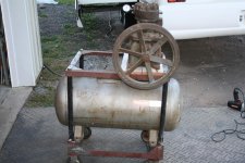
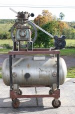
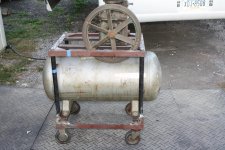
Somewhere around 30 year build project. In the mid/late 80's I snagged a refrigeration compressor along with a 3 phase motor. Motor went to scrap. Hauled the compressor around the country until 2008, when it got stuck in the corner of my current garage shop. Somewhere along the line (prior to 2000), I came upon a barrel holder for a 55 gal drum on casters.The last couple years is spent some time under my Grizzly shaper until I sold that. And all along I accumulated parts - fittings, check valve, pressure switch, relief valve, etc.

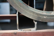
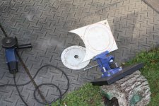
So a couple days ago I took the cutoff wheel to the barrel holder, and chopped it up, as did I cut some black iron pipe. A little welding and presto - compressor frame. Oh yeah, two years ago I happened on the tank for $25, that's been sitting in the garage also. Still a lot of work ahead, as I guess I'll have to source some angle iron for compressor and motor mounts. I dropped the compressor on the top of the frame on a couple of pieces of 1X4, just to get a feel for what's next. Obviously it has to move back and the pulley needs to go inside the frame, which is going to leave a really short distance for the motor mount, so it will probably overhang the top frame.

I guess I could put a riser block under the compressor so the pulley clears the frame and move it to the right some. Decisions, decisions; and, have to pick a motor - have a 2 HP and a 3 HP, both 3450 RPM. Might luck out and find a 1750 one, but that may extend the project. :willy_nil

I'm on a budget, so no telling when it will all come together. :dunno: Still cant decide how to mount the tank, right now it's on 2X2 thin wall tubing, have thought using a 2X6, but that doesn't seem right. Perhaps angle iron?

Anyway, someday........ ;)
 

Attachments

  • IMG_4704.jpg
    IMG_4704.jpg
    144.2 KB · Views: 99
  • IMG_4712.jpg
    IMG_4712.jpg
    152.5 KB · Views: 88
  • IMG_4714.jpg
    IMG_4714.jpg
    146 KB · Views: 125
  • IMG_4715.jpg
    IMG_4715.jpg
    140.5 KB · Views: 104
To avoid these ads, REGISTER NOW!

Outlander

Well-known member
Joined
Jul 30, 2010
Messages
5,154
Location
Quebec, Canada
I've had a new toilet seat in the bathroom cupboard for a year. Daughter issued me an ultimatum this week - change it or she will never move out. Be back in a few minutes guys..........
 
OP
A

Alchymist

Well-known member
Joined
Mar 1, 2009
Messages
4,423
Location
Central PA
Quick update. Compressor mounted, (will come back off for painting the mount), had to cut the brackets down just a smidge more so I can get belts on/off the pulley. Oops! Anyway, fixed that. Still working on mounting the tank, nothing seems to fit just right, Tomorrow cutting up some 1X2 tubing to see if that will work. Also looks like the motor will have to overhang the side of the cart. Always something.
 

Attachments

  • IMG_4719.jpg
    IMG_4719.jpg
    148.7 KB · Views: 75
  • IMG_4718.jpg
    IMG_4718.jpg
    139.8 KB · Views: 51
  • IMG_4716.jpg
    IMG_4716.jpg
    146.2 KB · Views: 56

MikeF2316

Well-known member
Joined
Dec 29, 2012
Messages
9,605
Location
Thornhill, ON
Quick update. Compressor mounted, (will come back off for painting the mount), had to cut the brackets down just a smidge more so I can get belts on/off the pulley. Oops! Anyway, fixed that. Still working on mounting the tank, nothing seems to fit just right, Tomorrow cutting up some 1X2 tubing to see if that will work. Also looks like the motor will have to overhang the side of the cart. Always something.

Dude, slow down, pace yourself. You're going to be done before Christmas at this rate! :lol_hitti
 
OP
A

Alchymist

Well-known member
Joined
Mar 1, 2009
Messages
4,423
Location
Central PA
Dude, slow down, pace yourself. You're going to be done before Christmas at this rate! :lol_hitti

:lol:

Yeah, got to grab some welding rods. The 7018 I've got (couple # left), are really old, and don't work well. Hard to strike, keep flaring out. Bummer. Anyway, will slow me down some, as I won't be able to get any til next Wed. Guess I'll cut the 1X2 tube and tack it in for a trial run, but that's it. :rolleyes2

Guess I'll start calling it the Frankencompressor.
 

2oolhound

Well-known member
Joined
Dec 18, 2010
Messages
5,918
Location
BC Canada
Cool, I'm working on a similar compressor project except you've got me beat pretty bad on the time span.
One thing I'm seeing is this thing is getting pretty high off the ground. You could lower the top frame 3 inches or so by cutting down the pipes. Also the angle iron short top cross piece on left could be eliminated because the 2 x 6 replaces the need for it. Then if you took the right top cross angle iron off and welded it on the top of the top side rails you could lower the whole thing more than 3 inches.

I'd also like to see you lower the frame so the wheels are closer to the tank. You could gain 5 inches there. Maybe using the feet already welded to the tank somehow.

Lastly the motor hanging off the back doesn't bother me but I'm wondering if there is any advantage of having the the motor pulley lower than the compressor pulley like that. My gut feeling is to raise the motor so you can use a shorter belt.
 
OP
A

Alchymist

Well-known member
Joined
Mar 1, 2009
Messages
4,423
Location
Central PA
Cool, I'm working on a similar compressor project except you've got me beat pretty bad on the time span.
One thing I'm seeing is this thing is getting pretty high off the ground. You could lower the top frame 3 inches or so by cutting down the pipes. Also the angle iron short top cross piece on left could be eliminated because the 2 x 6 replaces the need for it. Then if you took the right top cross angle iron off and welded it on the top of the top side rails you could lower the whole thing more than 3 inches.

I'd also like to see you lower the frame so the wheels are closer to the tank. You could gain 5 inches there. Maybe using the feet already welded to the tank somehow.

Lastly the motor hanging off the back doesn't bother me but I'm wondering if there is any advantage of having the the motor pulley lower than the compressor pulley like that. My gut feeling is to raise the motor so you can use a shorter belt.

I don't think height is going to be a problem, it's pretty steady as is. I am thinking about doing away with the 3X5 compressor risers, and drop the compressor down with the pulley inside the frame, but that may shorten the distance between motor and compressor pulleys too much. Course I could put an idler on the belt by the motor to increase the wrap. :dunno: Will look at it after I get the tank secured.

As to the motor being lower has little effect on belt length; have to buy new belts anyway. One consideration was the tank not be a structural part of the unit, as the compressor I believe is probably twice the weight of the original compressor. Just a guess.
 

2oolhound

Well-known member
Joined
Dec 18, 2010
Messages
5,918
Location
BC Canada
Is there a recommended wrap on the pulleys? I've just switched from a long tank to a short tank but I think I'm ok for the amount of wrap on the pulleys.
 

nine4gmc

Well-known member
Joined
Mar 24, 2012
Messages
14,357
Location
Dallas
ahhh, the ol pulley wrap conundrum... Only at GJ will you find someone who cares. I don't think the OP has even used a tape measure yet, much less calculator or pen and paper to figure out pulley wrap. :lol_hitti

Is there a model number or brand on that compressor? Rated horsepower recommendation?

I almost picked up a Quincy compressor head last week but decided it was too much work to start a new project atm. Maybe one day, for now I'll live vicariously through you.
 
OP
A

Alchymist

Well-known member
Joined
Mar 1, 2009
Messages
4,423
Location
Central PA
Is there a recommended wrap on the pulleys? I've just switched from a long tank to a short tank but I think I'm ok for the amount of wrap on the pulleys.

If it's not slipping, it's ok! :lol:

ahhh, the ol pulley wrap conundrum... Only at GJ will you find someone who cares. I don't think the OP has even used a tape measure yet, much less calculator or pen and paper to figure out pulley wrap. :lol_hitti

Is there a model number or brand on that compressor? Rated horsepower recommendation?

I almost picked up a Quincy compressor head last week but decided it was too much work to start a new project atm. Maybe one day, for now I'll live vicariously through you.

Actually I use the Mark 1 eyeball calculator for stuff like that! As to wrap, the problem is always with the smaller pulley, the smaller the drive pulley, the more wrap on the larger pulley.

As to the compressor, Google can find nothing from the limited info - Has the numbers cast in - AD169, Model # D791, and the letter L inside a keystone shaped box.

It's huge, heavy, and old. Was a refrigeration compressor, twin cylinder, and the pulley is a 16" OD double sheave.

Today's task is tank mounting. If successful, a look at redoing the compressor mount to get the pulley inside the frame.
 

Roberts210

Well-known member
Joined
Dec 21, 2015
Messages
3,177
Location
Missouri
Don't ya love it when some things that have been sitting around for a few years comes together into a great project. It's very satisfying.
 
OP
A

Alchymist

Well-known member
Joined
Mar 1, 2009
Messages
4,423
Location
Central PA
Update:
Used the 1X2 tubing for the tank mounts, worked out OK. Cut out the 3X5 riser blocks, and dropped the compressor down inside the frame. (Pic looks like the pulley isn't parallel, it is). Might have a problem with the belt wrap on the motor pulley, will cross that bridge when I get the motor on. Hope I can keep the motor at least partially within the top frame outline. :fingersx:
 

Attachments

  • IMG_4720.jpg
    IMG_4720.jpg
    148.6 KB · Views: 41
  • IMG_4722.jpg
    IMG_4722.jpg
    147.9 KB · Views: 40

2oolhound

Well-known member
Joined
Dec 18, 2010
Messages
5,918
Location
BC Canada
That looks a whole lot better on the top end.

Do you have a grease pit or is that checker plate just covering pot holes?
 
To avoid these ads, REGISTER NOW!
OP
A

Alchymist

Well-known member
Joined
Mar 1, 2009
Messages
4,423
Location
Central PA
That looks a whole lot better on the top end.

Do you have a grease pit or is that checker plate just covering pot holes?

Neither - it's horse (cow?) stall rubber mats. I put them there to ease moving my woodworking equipment outside. They don't roll well on the dirt/gravel driveway. The mats were "free", they were in the barn when we bought the place. Another procrastination - it took me 7 years to decide to move them from the barn to the driveway, after contemplating pouring a concrete pad. :rolleyes2
 
OP
A

Alchymist

Well-known member
Joined
Mar 1, 2009
Messages
4,423
Location
Central PA
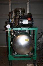
Another update. No longer is it the Frankencompressor, it shall forthwith be known as the Green Monster. :D

Got the frame finish welded, primed and mostly painted. Note the top is setting there upside down, the actual top of the top so to speak is not painted, as I still have to weld on a motor mount. I lost count how many times that compressor has hung from the chain fall. :headscrat
 

Attachments

  • IMG_4743.jpg
    IMG_4743.jpg
    137.5 KB · Views: 25
  • IMG_4744.jpg
    IMG_4744.jpg
    140.7 KB · Views: 28
OP
A

Alchymist

Well-known member
Joined
Mar 1, 2009
Messages
4,423
Location
Central PA
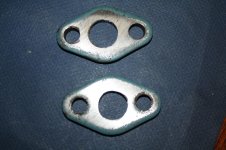
Little more done today, rounding up parts, shining the brass fittings, and some more paint. Top frame back on, top painted except where motor mount goes.

1st pic is couple blanks drilled out for inlet/outlet adapters, second is adapters tapped and on compressor temporarily, (mostly so I don't lose them!).

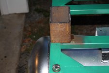
Third pic is tank cleaned, painted and back in the frame, and 4th is start of the motor mount, tomorrows project. Looks like a 1/4" plate on top of the tubing, and a heavy hinge to mount the motor to the plate.
 

Attachments

  • IMG_4747.jpg
    IMG_4747.jpg
    136.3 KB · Views: 17
  • IMG_4746.jpg
    IMG_4746.jpg
    134.6 KB · Views: 23
  • IMG_4748.jpg
    IMG_4748.jpg
    134.8 KB · Views: 14
  • IMG_4745.jpg
    IMG_4745.jpg
    145.6 KB · Views: 17
OP
A

Alchymist

Well-known member
Joined
Mar 1, 2009
Messages
4,423
Location
Central PA
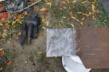
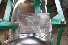
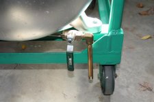
Not much done today. Yesterday fitted up some of the plumbing fittings - still short some. Cut out a base for the motor to mount on. Projects utilizing the scrap box can really soak up the time - took probably a 1/2 hour to clean, cut and dress the 1/4" rusty plate for the motor base. Will probably cut a little off the drain pipe next to the caster and clamp it to the frame. Now have to order the drive belt before I can finish up the motor mount. Looks like a 64 or 66 inch belt. Measures 65-1/2 inches OD on the test belt.
 

Attachments

  • IMG_4751.jpg
    IMG_4751.jpg
    152.5 KB · Views: 13
  • IMG_4752.jpg
    IMG_4752.jpg
    146.6 KB · Views: 14
  • IMG_4753.jpg
    IMG_4753.jpg
    128.5 KB · Views: 15

2oolhound

Well-known member
Joined
Dec 18, 2010
Messages
5,918
Location
BC Canada
Man, I can't believe how nice the tank turned out. (at least in the photos). Did you sand blast it or just sand? If mine turns out 1/2 that good I'll be happy.

I know how utilizing material from the scrap heap takes time. Most of my stock is either rusted or covered in different colours of powder coat, but it was a whole lot cheaper than the metal warehouse and I didn't have to make an hour long trip to go get it. ;) I still have to envy those with active shops who stock a good variety of new material that just needs to be cut to size and welded in place.
 
OP
A

Alchymist

Well-known member
Joined
Mar 1, 2009
Messages
4,423
Location
Central PA
No sanding, the tank had very little in the way of scratches or marring. Just wiped it down with mineral spirits, and a coat of Rustolium rattlecan.
 

metaldad

Well-known member
Joined
Aug 2, 2011
Messages
7,769
Location
nw indiana
nice build. i gather ,,,,,,,,an air compressor w/ receiver tank.
not trying to rain on your parade, but,
refrigeration rated compressors do pump a little oil. need oil separator at your air station.
tank............... did you inspect it internally? is it pressure rated? looks like there's a tag in post 3, third pic. should have a rating stamped on it. be sure to include a relief valve not exceeding it's rating, sized for the cfm of the pump, provided it is a pressure vessel.
drain valve on the bottom, excellent
 
OP
A

Alchymist

Well-known member
Joined
Mar 1, 2009
Messages
4,423
Location
Central PA
nice build. i gather ,,,,,,,,an air compressor w/ receiver tank.
not trying to rain on your parade, but,
refrigeration rated compressors do pump a little oil. need oil separator at your air station.
tank............... did you inspect it internally? is it pressure rated? looks like there's a tag in post 3, third pic. should have a rating stamped on it. be sure to include a relief valve not exceeding it's rating, sized for the cfm of the pump, provided it is a pressure vessel.
drain valve on the bottom, excellent

Tag has a 165# pressure rating, I filled it with water & pressurized to a little over 150, (high as I could go), and left it sit. No problems. Have dual popoff valves rated 145 PSI, and a Schrader Bellows separator for it. Separator has 1" ports and from their charts very little pressure drop across it at the flow values I plan on. Shooting for a 125 PSI cutoff.
 

metaldad

Well-known member
Joined
Aug 2, 2011
Messages
7,769
Location
nw indiana
very good, alchy.
refrigeration compressors are usually forced oil lubed. may be direction specific. there may be a directional arrow on the flywheel, if it's original
reefer pumps, especially that style, can take a beating and keep on ticking.
if needed, a valve plate assembly should be available.
(been awhile since i worked on an 'open' drive'. and with the massive ongoing industry consolidation , whatever is available these days is up for grabs)
 
OP
A

Alchymist

Well-known member
Joined
Mar 1, 2009
Messages
4,423
Location
Central PA
very good, alchy.
refrigeration compressors are usually forced oil lubed. may be direction specific. there may be a directional arrow on the flywheel, if it's original
reefer pumps, especially that style, can take a beating and keep on ticking.
if needed, a valve plate assembly should be available.
(been awhile since i worked on an 'open' drive'. and with the massive ongoing industry consolidation , whatever is available these days is up for grabs)

Yep, directional arrow on the back of the housing. Clockwise from the front of the flywheel, as were most of those I have encountered.
 
OP
A

Alchymist

Well-known member
Joined
Mar 1, 2009
Messages
4,423
Location
Central PA
Update - air filter done -
 

Attachments

  • IMG_4810.jpg
    IMG_4810.jpg
    139.8 KB · Views: 16
  • IMG_4809.jpg
    IMG_4809.jpg
    139 KB · Views: 15
  • IMG_4808.jpg
    IMG_4808.jpg
    149.2 KB · Views: 14
OP
A

Alchymist

Well-known member
Joined
Mar 1, 2009
Messages
4,423
Location
Central PA
No pics this time, not much changed. Motor mount made (not painted yet), pressure switch & belts received.Turns out the check valve I had doesn't check, so need to find a new one. Ginned things up so I could do a trial run, without a check valve or press switch. Only took it to 80 PSI to check for obvious leaks in the permanent parts of the plumbing. Was quite surprised at how quiet it ran. Nothing near as loud as some of those smaller ones.

Anyway, build is progressing, soon as I can pick up a check valve and get the rest of the plumbing in place, will take it on up to 125 PSI. Then comes the guard fab. If my calculations are correct, it's putting out about 12-13 Cu Ft/min at 80 PSI, so I should hit somewhere around 8 or 9 at 125 PSI.
 
OP
A

Alchymist

Well-known member
Joined
Mar 1, 2009
Messages
4,423
Location
Central PA
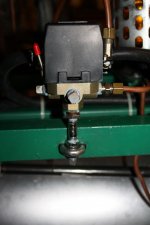
Some progress today. Pressure switch mounted, motor base painted. Wiring done. Pressure switch was a pain - tight quarters for 6 #12 wires. Pipe from tank to PS installed ok, still working on the one from unloader to compressor. The compression fitting on the PS ***** - ferrule would not go over the copper pipe. No way, no how. Even took a round file to the ferrule and sand paper to the tubing. Finally tossed the ferrule and nut and used one of mine, hope it seals.

Made a kludge tool for tightening the belts from a turnbuckle and a big washer. Still having problems welding, but got it bubble gummed together. Worked a treat.

Checked out PS operation - cutout was right on @ 125 PSI, but cut in was off at about 80 PSI, not the 95 specified. Will play with the adjustments later.

Which brings me to a bit of a puzzle. When I ran the thing up to 80 PSI earlier, I calculated about 13 Cu Ft/min, so I figured I might get 8-9 @125. Did the calcs and it still comes out to 13. :dunno: Will re run it again later when I get the unloader connected. (Trip to town for check valve, naturally).

Pics of the tool and PS install.
 

Attachments

  • IMG_4813.jpg
    IMG_4813.jpg
    148.9 KB · Views: 7
  • IMG_4814.jpg
    IMG_4814.jpg
    137.4 KB · Views: 8
  • IMG_4815.jpg
    IMG_4815.jpg
    132.9 KB · Views: 8
  • IMG_4816.jpg
    IMG_4816.jpg
    128.7 KB · Views: 6
To avoid these ads, REGISTER NOW!
Top Bottom