To avoid these ads, REGISTER NOW!

Project 66 Rustang

To avoid these ads, REGISTER NOW!
OP
B

bigguns69

Well-known member
Joined
Aug 23, 2011
Messages
411
Location
Iowa
Partial kick panel replacement. The door pillar is in good shape and the panel on the backside was in good shape. Decided to do a partial repair here. Starting to go back together, a little.
 

Attachments

  • IMG_6304.jpg
    IMG_6304.jpg
    142.6 KB · Views: 140
  • IMG_6310.jpg
    IMG_6310.jpg
    138.4 KB · Views: 177
  • IMG_6309.jpg
    IMG_6309.jpg
    145.7 KB · Views: 136
  • IMG_6308.jpg
    IMG_6308.jpg
    144.4 KB · Views: 137
  • IMG_6307.jpg
    IMG_6307.jpg
    142.1 KB · Views: 145
  • IMG_6306.jpg
    IMG_6306.jpg
    144.6 KB · Views: 133
  • IMG_6305.jpg
    IMG_6305.jpg
    147.6 KB · Views: 132
OP
B

bigguns69

Well-known member
Joined
Aug 23, 2011
Messages
411
Location
Iowa
With the kick panels in place, I am ready for the new firewall. With the back of the dash panel exposed, you can see the light surface rust. Bare steel from the factory back then, not good for longevity.

Got the HF spot sand blaster out and removed the rust and then coated it with some self etching primer. Used the inner cowl panel to help align everything in place. Had to do a little dolly work to shape the tops of the kick panels to fit the inner cowl perimeter profile.

Drilled a bunch of .28" D holes in the side flanges of the firewall. Clamped it up and rosette weld time. Had a hard time welding things up without burning through everything. Using a Miller 251 with .035 wire and had it turned all the way down. Was a little frustrating for sure. Sheet metal is all 18 ga. or about .046" thick.
 

Attachments

  • IMG_6341.jpg
    IMG_6341.jpg
    127.8 KB · Views: 149
  • IMG_6340.jpg
    IMG_6340.jpg
    123.6 KB · Views: 175
  • IMG_6339.jpg
    IMG_6339.jpg
    125.7 KB · Views: 151
  • IMG_6338.jpg
    IMG_6338.jpg
    138 KB · Views: 148
  • IMG_6325.jpg
    IMG_6325.jpg
    144.1 KB · Views: 155
  • IMG_6324.jpg
    IMG_6324.jpg
    138.2 KB · Views: 161
  • IMG_6323.jpg
    IMG_6323.jpg
    138.8 KB · Views: 154
OP
B

bigguns69

Well-known member
Joined
Aug 23, 2011
Messages
411
Location
Iowa
Pictures showing the firewall in place. Starting to make some progress now. Ready to get started with the inner cowl install. Need a lot of holes. Got a hand punch to speed up the process. Easier than drilling but sets in fatigue with the hands as the punch breaks through the metal. The new replacement metal is harder than the old stuff, can definitely feel it.
 

Attachments

  • IMG_6364.jpg
    IMG_6364.jpg
    131.9 KB · Views: 174
  • IMG_6350.jpg
    IMG_6350.jpg
    127.7 KB · Views: 168
  • IMG_6349.jpg
    IMG_6349.jpg
    136.6 KB · Views: 157
  • IMG_6348.jpg
    IMG_6348.jpg
    147.8 KB · Views: 174
  • IMG_6344.jpg
    IMG_6344.jpg
    136.9 KB · Views: 167
  • IMG_6343.jpg
    IMG_6343.jpg
    132.4 KB · Views: 144
  • IMG_6342.jpg
    IMG_6342.jpg
    137.2 KB · Views: 154

MP&C

Well-known member
Joined
Oct 21, 2009
Messages
4,396
Location
Leonardtown, MD
Referring to the chart from Miller:

https://www.millerwelds.com/-/media...sources/weldingresources/mig_welding_tips.pdf


.024, .030, and .035 are all within the range for 18 gauge sheet metal. Don't rush out to buy a new spool of wire without trying the "free" fixes first.

As with any other "blowout" in non-rusty sheet metal, too much heat for the given AMOUNT of filler. That doesn't necessarily mean to turn down the heat. My suggestion is to try increasing the wire feed. This also works to fill the plug weld hole more quickly so you aren't sitting there all day. Having said that, I set my welder hot for plug welds but only use a Letter A hole size, .234" diameter. Again, not sitting there all day trying to fill too large a hole. Sure, I-CAR calls for about 5/16", but they also are trying to insure body shops get good weld penetration. When is the last time you saw a 5/16 diameter factory spot weld?

If you are using the Whitney JR for punching your holes, drop down to the .218 size (7/32) and try again..
 
Last edited:
OP
B

bigguns69

Well-known member
Joined
Aug 23, 2011
Messages
411
Location
Iowa
Still playing catch up of my posts to progress so far. Like mentioned above, I moved to .023" wire and that made a world of difference. Previous to this car build, sheet metal to me was 11 ga.

I did end up buying a Miller 211 110v/220v welder and set it up as my exclusive, light duty machine. I like the smaller size, smaller gun for climbing around on the car, plus it’s portable. Planning on setting it up with a spool gun for aluminum in the future. It works great. I welded a 1" rust hole shut with it just to see how good I could do.

Appreciate the ideas. I need to go to HF and get that pneumatic punch.
 
OP
B

bigguns69

Well-known member
Joined
Aug 23, 2011
Messages
411
Location
Iowa
Finished the inner cowl panel install, grinding spot welds smooth. Prepped the interior surfaces of the cowl weldment assembly with Summit single stage urethane gloss black paint for extra layer of element protection. The paint sprayed well, about $110 for the gallon kit, and hardened up in about 30 minutes.
 

Attachments

  • IMG_6405.jpg
    IMG_6405.jpg
    142.7 KB · Views: 172
  • IMG_6403.jpg
    IMG_6403.jpg
    141.9 KB · Views: 148
  • IMG_6421.jpg
    IMG_6421.jpg
    143.1 KB · Views: 160
  • IMG_6371.jpg
    IMG_6371.jpg
    132.4 KB · Views: 149
  • IMG_6370.jpg
    IMG_6370.jpg
    131 KB · Views: 154
  • IMG_6369.jpg
    IMG_6369.jpg
    135 KB · Views: 156
OP
B

bigguns69

Well-known member
Joined
Aug 23, 2011
Messages
411
Location
Iowa
Decided to put some seam sealer around the vent buckets to provide a little extra protection from rust, at the last minute. 3M brushable seam sealer applied with an acid brush. Cures in about an hour. Put a coat of paint over top to finish it off.
 

Attachments

  • IMG_6420.jpg
    IMG_6420.jpg
    133.7 KB · Views: 151
  • IMG_6419.jpg
    IMG_6419.jpg
    130.6 KB · Views: 150
  • IMG_6417.jpg
    IMG_6417.jpg
    141.9 KB · Views: 159
  • IMG_6416.jpg
    IMG_6416.jpg
    142.4 KB · Views: 154
  • IMG_6415.jpg
    IMG_6415.jpg
    137.4 KB · Views: 143
  • IMG_6414.jpg
    IMG_6414.jpg
    141.8 KB · Views: 162
OP
B

bigguns69

Well-known member
Joined
Aug 23, 2011
Messages
411
Location
Iowa
Finished up the outer cowl install. Lots of holes, spot welds, and grinding. This is where vice grips come into play and a few sheet-metal screws to draw everything tight.

The rear of the outer cowl flange connects to the front flange of the metal dash frame. This is where the rubber seal for the bottom of the windshield glass will reside when done. Forward of that about an inch is where the inner and outer cowl connect. This required the use of some sheet-metal screws to draw the joint tight before welding.

I used a pick to scribe the paint away for each spot weld. That got old after a while so I took a 1/4" drill bit and ground the end flat and used a hand drill to break the paint loose. Etching primer to finish it off. Not bad for first time doing this.
 

Attachments

  • IMG_6692.jpg
    IMG_6692.jpg
    133.9 KB · Views: 152
  • IMG_6693.jpg
    IMG_6693.jpg
    134.3 KB · Views: 161
  • IMG_6659.jpg
    IMG_6659.jpg
    135.1 KB · Views: 171
  • IMG_6658.jpg
    IMG_6658.jpg
    133.2 KB · Views: 156
  • IMG_6657.jpg
    IMG_6657.jpg
    134.5 KB · Views: 157
  • IMG_6656.jpg
    IMG_6656.jpg
    133.9 KB · Views: 163
  • IMG_6655.jpg
    IMG_6655.jpg
    130 KB · Views: 153

C_F

ALLIANCE MEMBER
Joined
Jan 21, 2005
Messages
9,675
Location
Utah...SNOW BLOWS!
I just found your thread today, great project! I really like the body dolly & jig setup, I may have to steal that idea at some point in the future. :)

Are these photos where you're currently at? I will enjoy checking back in for your continued progress photos, keep at it!
 

AngryBeaver

Well-known member
Joined
Jul 12, 2017
Messages
1,705
Location
Lake Milton Ohio
Fun build. Mines ripped apart doing a mini tub and AJE front end.

Then a 04 cobra engine and trans with the 9" I already have in mine.


attachment.php
 

Attachments

  • IMG_6074.jpg
    IMG_6074.jpg
    146.3 KB · Views: 929

Jazz1

Well-known member
Joined
Jan 3, 2016
Messages
4,184
Location
Thunder Bay On.
Honestly, even though its not as fun as other stuff, I'd get that body work done before I spend a dime on go fast parts.

Thats sage advice. Body work is such a time consuming and tedious task. No time for bodywork the project will not get completed but as I look through the thread wow that is a ambitious project. I have worked on a couple rustangs, fell through the floor of a '65 fastback while removing glass trim.
 
Last edited:
OP
B

bigguns69

Well-known member
Joined
Aug 23, 2011
Messages
411
Location
Iowa
The replacement firewall, in the transition to the floor pan, does not extend fully to the kick panel with a flange. Since I am not worried about a factory equivalent rebuild, I used some 1" x 11 ga. angle to make the connection. Connected what remains of the floor pan tunnel to get structure back to the weldment. The tunnel will get some rework with the new floor pans later.
 

Attachments

  • IMG_7037.jpg
    IMG_7037.jpg
    122.3 KB · Views: 121
  • IMG_7038.jpg
    IMG_7038.jpg
    141.2 KB · Views: 127
  • IMG_7036.jpg
    IMG_7036.jpg
    132.8 KB · Views: 136
  • IMG_7035.jpg
    IMG_7035.jpg
    127 KB · Views: 118
  • IMG_7034.jpg
    IMG_7034.jpg
    128.2 KB · Views: 123
  • IMG_7033.jpg
    IMG_7033.jpg
    129.6 KB · Views: 125
  • IMG_7031.jpg
    IMG_7031.jpg
    135.2 KB · Views: 130
OP
B

bigguns69

Well-known member
Joined
Aug 23, 2011
Messages
411
Location
Iowa
Frame time. Going with 2 x 3 x 11 ga. rectangular tube. Started laying things out with wood to see where things fit with the firewall / pan area. Decided to install some 11 ga. plate on the pans for the tube to **** up to for good weld contact. Me being a former earth moving/combine engineer is starting to show in how I put things together.
 

Attachments

  • IMG_7048.jpg
    IMG_7048.jpg
    137.9 KB · Views: 143
  • IMG_7044.jpg
    IMG_7044.jpg
    129.8 KB · Views: 138
  • IMG_7043.jpg
    IMG_7043.jpg
    124.6 KB · Views: 139
  • IMG_7042.jpg
    IMG_7042.jpg
    125.1 KB · Views: 129
  • IMG_7041.jpg
    IMG_7041.jpg
    127.3 KB · Views: 133
  • IMG_7040.jpg
    IMG_7040.jpg
    124.6 KB · Views: 132
  • IMG_7039.jpg
    IMG_7039.jpg
    137.2 KB · Views: 140

ScottsGT

Well-known member
Joined
Jan 1, 2014
Messages
4,883
Location
Lake Wateree, SC
Are you going to tie the new rails to the bottom of the pan too? I installed subframe connectors on mine. Really made a nice stiff chassis.
 
OP
B

bigguns69

Well-known member
Joined
Aug 23, 2011
Messages
411
Location
Iowa
Pictures of front frame basic weld up with left and right side fender aprons welded on. Decided to stitch weld both side of the flanges rather than punching holes and spot welding in most of the areas. The flanges on the new apron parts were really narrow and If I popped holes in them there would not be much metal around them.
 

Attachments

  • IMG_7088.jpg
    IMG_7088.jpg
    139.6 KB · Views: 150
  • IMG_7085.jpg
    IMG_7085.jpg
    133.2 KB · Views: 155
  • IMG_7083.jpg
    IMG_7083.jpg
    142.1 KB · Views: 147
  • IMG_7082.jpg
    IMG_7082.jpg
    139.8 KB · Views: 151
  • IMG_7054.jpg
    IMG_7054.jpg
    137.6 KB · Views: 150
  • IMG_7050.jpg
    IMG_7050.jpg
    124.3 KB · Views: 149
  • IMG_7049.jpg
    IMG_7049.jpg
    133.2 KB · Views: 151
OP
B

bigguns69

Well-known member
Joined
Aug 23, 2011
Messages
411
Location
Iowa
More pictures of frame, aprons, front, and tie in to cowl/firewall. Used 11 ga. flat bar to tie the aprons to the frame rails.
 

Attachments

  • IMG_7101.jpg
    IMG_7101.jpg
    144.4 KB · Views: 121
  • IMG_7098.jpg
    IMG_7098.jpg
    133.6 KB · Views: 125
  • IMG_7096.jpg
    IMG_7096.jpg
    139.6 KB · Views: 124
  • IMG_7095.jpg
    IMG_7095.jpg
    139.2 KB · Views: 121
  • IMG_7094.jpg
    IMG_7094.jpg
    139.2 KB · Views: 118
  • IMG_7092.jpg
    IMG_7092.jpg
    133.9 KB · Views: 115
  • IMG_7090.jpg
    IMG_7090.jpg
    142.6 KB · Views: 127
To avoid these ads, REGISTER NOW!
OP
B

bigguns69

Well-known member
Joined
Aug 23, 2011
Messages
411
Location
Iowa
Planning on grafting a tube frame onto the new floor pans and into the rear rails. This is an example of what I plan on doing. The rear frame and floor panels seem fairly solid. I need a rotisserie.
 

Attachments

  • three.jpg
    three.jpg
    69.4 KB · Views: 229
  • post-1742-074011500%201351794636.jpg
    post-1742-074011500%201351794636.jpg
    99.6 KB · Views: 274
  • IMG_3945.jpg
    IMG_3945.jpg
    111 KB · Views: 263
  • four.jpg
    four.jpg
    65 KB · Views: 305
  • five.jpg
    five.jpg
    59.6 KB · Views: 280
OP
B

bigguns69

Well-known member
Joined
Aug 23, 2011
Messages
411
Location
Iowa
I built a rotisserie. Took about 2 solid weekends to get done. I think I've spent about as much time building carts, engine run stand, frame jig, and rotisserie as I have spent on the car so far. Guess I will be better prepared for next time.

See details in other post. I have been wanting too do this for a long time. I am having a blast working on this thing. Can't wait to work on the next one, going to throw caution to the wind on that one.
 

Attachments

  • IMG_7174.jpg
    IMG_7174.jpg
    146.8 KB · Views: 214
  • IMG_7172.jpg
    IMG_7172.jpg
    146.4 KB · Views: 194
  • IMG_7175.jpg
    IMG_7175.jpg
    147.5 KB · Views: 210
  • IMG_7171.jpg
    IMG_7171.jpg
    146.4 KB · Views: 228
  • IMG_7167.jpg
    IMG_7167.jpg
    146.8 KB · Views: 238

racer-john

Well-known member
Joined
Apr 1, 2008
Messages
1,461
Location
Newmarket, ON Canada
I build this frame jig at this stage

On page 18.
Is there anything joining the pairs of channels together other than the bolted plates shown in pic three, or are they just loose when you store them?

Enjoyed your work so far, will be looking for progress reports.:thumbup
TIA racer-john
 
OP
B

bigguns69

Well-known member
Joined
Aug 23, 2011
Messages
411
Location
Iowa
Racer-John:

There are several 3/4 x 3 1/2” solid bars welded between the channels to make them joined pairs.
 
OP
B

bigguns69

Well-known member
Joined
Aug 23, 2011
Messages
411
Location
Iowa
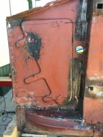
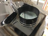
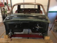
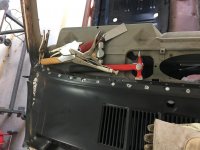
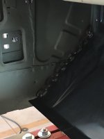
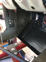
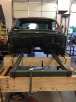
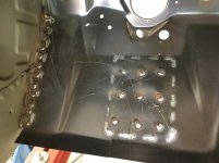
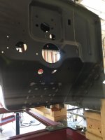
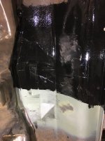
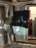
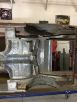
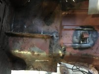
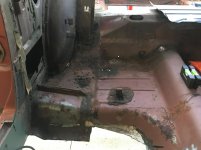
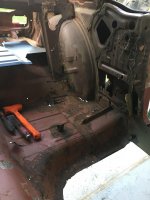
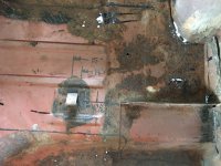
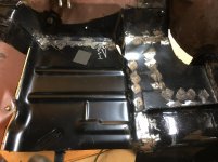
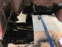
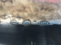
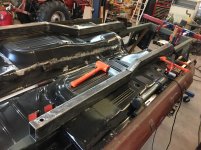
Been a while since last post. With car on rotisserie need to do some rust removal to see how bad the back half floor pan is. Did some wire wheeling and tried out some paint options. Did a test spot of both etching primer, Green, and Por 15, Black. Applied both, let dry for a day then came back and hit it with the wire wheel again to see which had better adhesion. The Por 15 bonded better to the metal so that's what I decided to go with.

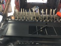
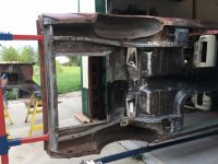
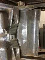
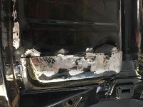
Did some sandblasting and a lot of grinding with flap discs to get the metal fairly clean. Sandblasting really runs my compressor hard so try to limit it to areas that I can't get to with a grinder.

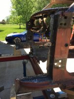
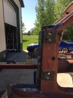
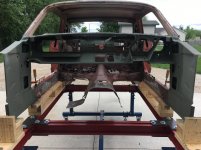
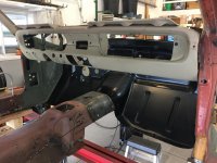
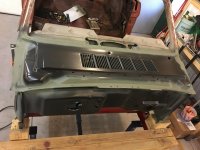
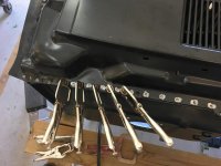
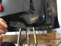
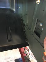
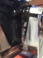
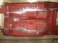
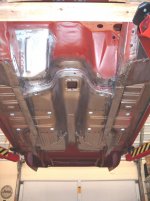
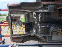
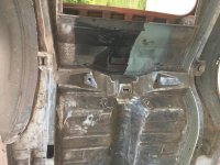
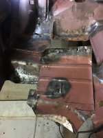
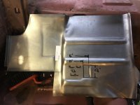
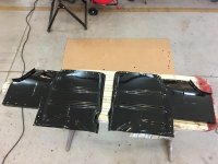
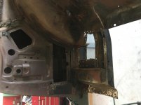
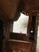
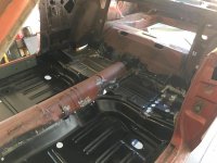
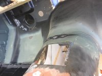
Rear left and right side floor pan extensions will need replaced along with the metal from the outside of the rear frame rail flange to wheel house and rear fender both sides.

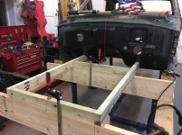
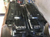
Focusing on floor pans, then new frame, then rear quarters and wheel houses and rear quarter extension pans.
 

Attachments

  • IMG_7293.jpg
    IMG_7293.jpg
    144.3 KB · Views: 131
  • IMG_7290.jpg
    IMG_7290.jpg
    143.2 KB · Views: 143
  • IMG_7285.jpg
    IMG_7285.jpg
    142.5 KB · Views: 137
  • IMG_7268.jpg
    IMG_7268.jpg
    140.4 KB · Views: 138
  • IMG_7266.jpg
    IMG_7266.jpg
    139.5 KB · Views: 140
  • IMG_7265.jpg
    IMG_7265.jpg
    142.4 KB · Views: 149
  • IMG_7264.jpg
    IMG_7264.jpg
    142.3 KB · Views: 157
OP
B

bigguns69

Well-known member
Joined
Aug 23, 2011
Messages
411
Location
Iowa
Rear left and right floor pan extension replacement. Out with the old. I have gone away from using the spot-weld cutter tool to using 1/4-5/16 size drill bits. I can sharpen them and cut through the spot-welds faster and cheaper then replacing the spot-weld cutter tool when dull. I cut the rear seat mount tangs off and save for remounting later.
 

Attachments

  • IMG_7311.jpg
    IMG_7311.jpg
    130 KB · Views: 116
  • IMG_7310.jpg
    IMG_7310.jpg
    135.6 KB · Views: 124
  • IMG_7309.jpg
    IMG_7309.jpg
    138.8 KB · Views: 121
  • IMG_7308.jpg
    IMG_7308.jpg
    136.5 KB · Views: 127
  • IMG_7307.jpg
    IMG_7307.jpg
    134.6 KB · Views: 116
  • IMG_7306.jpg
    IMG_7306.jpg
    131.1 KB · Views: 116
  • IMG_7305.jpg
    IMG_7305.jpg
    135.6 KB · Views: 124
OP
B

bigguns69

Well-known member
Joined
Aug 23, 2011
Messages
411
Location
Iowa
Removal, Prep of underside of new panels and prep of interior of frame rails before going back together.
 

Attachments

  • IMG_7323.jpg
    IMG_7323.jpg
    140.7 KB · Views: 98
  • IMG_7322.jpg
    IMG_7322.jpg
    133.2 KB · Views: 89
  • IMG_7321.jpg
    IMG_7321.jpg
    145.7 KB · Views: 86
  • IMG_7318.jpg
    IMG_7318.jpg
    129.8 KB · Views: 84
  • IMG_7316.jpg
    IMG_7316.jpg
    140 KB · Views: 89
  • IMG_7315.jpg
    IMG_7315.jpg
    136.5 KB · Views: 86
  • IMG_7314.jpg
    IMG_7314.jpg
    133.3 KB · Views: 89
OP
B

bigguns69

Well-known member
Joined
Aug 23, 2011
Messages
411
Location
Iowa
Going back together with the new rear pans. The passenger side came bare, the driver side came with primer.
 

Attachments

  • IMG_7348.jpg
    IMG_7348.jpg
    139.3 KB · Views: 113
  • IMG_7347.jpg
    IMG_7347.jpg
    132.1 KB · Views: 114
  • IMG_7328.jpg
    IMG_7328.jpg
    141 KB · Views: 130
  • IMG_7327.jpg
    IMG_7327.jpg
    137.8 KB · Views: 120
  • IMG_7326.jpg
    IMG_7326.jpg
    136.3 KB · Views: 120
  • IMG_7325.jpg
    IMG_7325.jpg
    132.7 KB · Views: 114
  • IMG_7324.jpg
    IMG_7324.jpg
    134.8 KB · Views: 112

ScottsGT

Well-known member
Joined
Jan 1, 2014
Messages
4,883
Location
Lake Wateree, SC
FWIW, if the green was epoxy, 24 hours was not enough time to give it a fair comparison. I used SPI epoxy and had a good long conversation with the owner of the company when I was prepping my '66 GT Fastback. He explained it best by comparing it to epoxy glue. Which it basically is. Can't start stressing a glue joint until it is fully cured. It takes up to a week to fully cure epoxy paint.
That's why you have a recoat time of 1 week using epoxy as a base. Fresh epoxy is basically gluing down what you just put on top of it. After a week, you have to sand it.
He also told me to spray an area. Wait 24 hours and scratch it off with my fingernail. Come back a week later and wear down my fingernail trying to scratch it off again.

That being said, the POR15 is also a very awesome product too. Can't go wrong either way. That stuff dries as hard as diamonds.

Love your rotisserie. I built one myself when I did my project but it was much "lower budget" than that masterpiece you put together!
 
OP
B

bigguns69

Well-known member
Joined
Aug 23, 2011
Messages
411
Location
Iowa
The Por 15 material is really good product and flows out well with a brush. It is kind of pricey too. If I get some on my skin, I wear it for a week or better. It is really hard on can lids too. Material really bites.
 
OP
B

bigguns69

Well-known member
Joined
Aug 23, 2011
Messages
411
Location
Iowa
Fitting the floor pans in place. Use pole barn screws to attach the new pans to the surrounding metal and draw tight. I then go around the perimeter and scribe a line with a scratch awl, then cut the old material to the line. Then fit the pans back in and **** weld the new to the old.

Lots of spot welds. I go around and tack around the perimeter to get every thing attached. I typically go with three spots then move to a different area to minimize warping to finish up. With the thin 18-20 ga material I can get 100% penetration by welding one side.

I have found that the best way for me to grind weld seems smooth without thinning the material is to us a cutoff tool with the cut off wheel perpendicular to the weld joint. Takes some time but I have a lot of control.

Also, had a big dent in the passenger side rocker panel. Chose to go at it from the inside out, so I cut a window out and used a customized chunk of 2x2 with some contour on the end to get it 95% before putting the floor pans in.
 

Attachments

  • IMG_7390.jpg
    IMG_7390.jpg
    141.8 KB · Views: 136
  • IMG_7387.jpg
    IMG_7387.jpg
    144.1 KB · Views: 137
  • IMG_7358.jpg
    IMG_7358.jpg
    145 KB · Views: 154
  • IMG_7357.jpg
    IMG_7357.jpg
    131.7 KB · Views: 137
  • IMG_7355.jpg
    IMG_7355.jpg
    138.2 KB · Views: 141
  • IMG_7431.jpg
    IMG_7431.jpg
    136.6 KB · Views: 135
  • IMG_7432.jpg
    IMG_7432.jpg
    126.9 KB · Views: 135
OP
B

bigguns69

Well-known member
Joined
Aug 23, 2011
Messages
411
Location
Iowa
Patch panel for the trans tunnel. Showing the single pass of spot welds on the underneath side, the full weld penetration through to the inside and then grinding the weld smooth. Couple of my spot welds at the trans to firewall overlap need a second going over.
 

Attachments

  • IMG_7410.jpg
    IMG_7410.jpg
    144.8 KB · Views: 106
  • IMG_7409.jpg
    IMG_7409.jpg
    140.7 KB · Views: 110
  • IMG_7408.jpg
    IMG_7408.jpg
    139.6 KB · Views: 105
  • IMG_7407.jpg
    IMG_7407.jpg
    143.7 KB · Views: 104
  • IMG_7404.jpg
    IMG_7404.jpg
    140.5 KB · Views: 103
  • IMG_7403.jpg
    IMG_7403.jpg
    134.8 KB · Views: 103
  • IMG_7402.jpg
    IMG_7402.jpg
    134.1 KB · Views: 104
OP
B

bigguns69

Well-known member
Joined
Aug 23, 2011
Messages
411
Location
Iowa
Time to finish up the frame. Pictures show a 2x2x11ga. mid tube and then the various 2x3x11ga. rect. tube to finish the connection of the front section to the back section.

The pans are flat in the front and back with a slope angle of about 7 degrees where the seat pans reside on the inside of the car. This requires some compound cuts, which I did with a right angel grinder and cutoff wheel.
 

Attachments

  • IMG_7496.jpg
    IMG_7496.jpg
    146.4 KB · Views: 156
  • IMG_7495.jpg
    IMG_7495.jpg
    136.4 KB · Views: 133
  • IMG_7494.jpg
    IMG_7494.jpg
    132.8 KB · Views: 135
  • IMG_7493.jpg
    IMG_7493.jpg
    141.9 KB · Views: 128
  • IMG_7488.jpg
    IMG_7488.jpg
    138.8 KB · Views: 134
  • IMG_7487.jpg
    IMG_7487.jpg
    132.9 KB · Views: 140
  • IMG_7498.jpg
    IMG_7498.jpg
    137.8 KB · Views: 142

ms fowler

Well-known member
Joined
Jun 27, 2012
Messages
450
Location
Littlestown, PA _ 6 miles south of Gettysburg
Nice looking thread--great work!

I would disagree with the statement that they were "built to rust". No one would do that, but they weren't built NOT to rust. They were designed and then built to be put together as rapidly as possible. There was GREAT demand for these when they were new. I read somewhere that the three most successful new car introductions in auto history were:1) 1928 Model A Ford. 2) 1960 Ford Falcon, and 3) 1965 Ford Mustang ( 64 1/2 for you purists). Built using many parts and most of the platform of the Falcon there was no thought that these cars would last for 10 years, let alone 50+. Cost was the key--sure they could have made them better, but the extra $100 or $400 would have killed them in the market.
 
To avoid these ads, REGISTER NOW!
Top Bottom