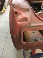
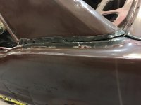
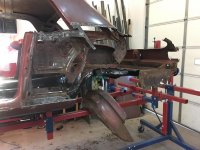
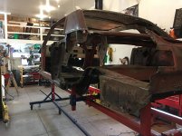
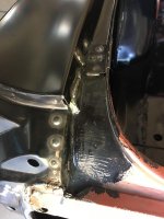
Stitch welded frame rails to the pans and grafted some scallop ends to the rear of the frame to blend into the existing rear frame rail. Showcasing a little CAD work, "Cardboard Aided Design" for the scallops.

You are using an out of date browser. It may not display this or other websites correctly.
You should upgrade or use an alternative browser.
You should upgrade or use an alternative browser.
Project 66 Rustang
- Thread starter bigguns69
- Start date
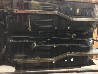


Added some fishplates to finish off the connection between the front and mid section of the frame. Added some 1x1x1/8" angle tabs to get additional contact between the frame and floor pans. Now the car has a full frame underneath it.
Attachments


jhn9840
Well-known member
Nice work to the car. Thanks for sharing.
jhn9840
John
jhn9840
John
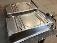
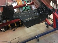
Seat pan time. Used the Harbor Freight pneumatic punch to create spot weld holes in the new seat pans. The seat pans are made of thick material 14-16 gage. Placed pans in and drew the joint tight with a few screws. I set the pans about an inch towards the rear to get a little more leg room when sitting in the seat. I made sure I could still access the seat mounting holes from the underneath side of the car through the pans access holes.
Punch and hammer to get the seam tight with the floor pans before welding. When spot welding, I run the welder about a gage level higher than recommended on the welder chart to get good penetration and get the rosette weld to lay down. Roughed up the pans in preparation of Por 15 coating.
Punch and hammer to get the seam tight with the floor pans before welding. When spot welding, I run the welder about a gage level higher than recommended on the welder chart to get good penetration and get the rosette weld to lay down. Roughed up the pans in preparation of Por 15 coating.
Attachments


larry4406
Well-known member
Nice.
I had tried one of the HF flanger/punches and it died a quick death. Hope yours does better. This was 3-4 years ago.
I had tried one of the HF flanger/punches and it died a quick death. Hope yours does better. This was 3-4 years ago.
tlmartin84
Well-known member
Didn't opt for the convertible pans?
I could never get a good spot weld with the 3/16 hole size...I used my HF punch/flanger a TON, but would end up drilling them out. The welder would always arc to the top piece and not penetrate the bottom.........
It is really nice for welding up holes though! Ive used mine to make lots of "plugs" to weld up PO holes......
ScottsGT
Well-known member
Didn't opt for the convertible pans?
I could never get a good spot weld with the 3/16 hole size...I used my HF punch/flanger a TON, but would end up drilling them out. The welder would always arc to the top piece and not penetrate the bottom.........
It is really nice for welding up holes though! Ive used mine to make lots of "plugs" to weld up PO holes......
Sounds like your welder is not set up right. I run the small .023 ? wire and crank up the heat and speed and even if I don't hit the hole exactly right, it melts together great after I flow the metal into the hole.
Boosted1
Well-known member
I just read your thread and enjoyed it.
Nice work.
Nice work.
p_mori7
Well-known member
Great Thread !
Very nice work.
~Phil
Very nice work.
~Phil
Hammer1963
Well-known member
Fantastic read and fabulous work! As a person that has performed this type of work for 25 plus years, your work is far superior to more than 90% of the vehicles that I have run across that were modified and repaired in this manor. Your engineering skills and understanding of the materials really shows. I enjoyed how you happened across new ideas and techniques for removing the old parts. The Blair cutters, grinding wheels, cut-off wheels etc. That is knowledge that comes from trial and error experience and a desire to improve.
I have a few ideas that you may like to look into. I only suggest these as they are from learning from failure and learning from others.
As you start the exterior sheet metal stage, I would recommend looking into using a combination of plug welding, stitch welding, solid panel welding in conjunction with a urethane and or epoxy bonding adhesive. The benefits of combining the adhesives with welding are tremendous including corrosion protection and adding strength overall to any area. It's clear that your goal is to overcome many of the short comings of the fabulous Rustang and this process will will help you achieve such. Something else I would recommend is the use of weld-through primer or pre-priming overlapping joints. I also use a lot of **** joints in exterior work often using a backing panel when needed.
I look forward to seeing future progress!
Appreciate the kind words. I’ve built a lot of custom combines and directional drills over the years. This is my first full fledged car build. I etch prime all interior metal surfaces before I weld together. Weld through is expensive and can’t mix up my own to spray.
My give a **** o meter has been pegged out for the last few months so haven’t made much progress on the car. Hopeful over Christmas I can get rear quarters and wheel wells replaced.
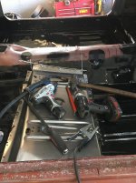
Pictures show old tool tray I usually work from. Doesn’t take long and get piled up with tools then I get frustrated digging for things. Got a HF mobile tool cart and made some modifications to my liking so far.
My give a **** o meter has been pegged out for the last few months so haven’t made much progress on the car. Hopeful over Christmas I can get rear quarters and wheel wells replaced.
Pictures show old tool tray I usually work from. Doesn’t take long and get piled up with tools then I get frustrated digging for things. Got a HF mobile tool cart and made some modifications to my liking so far.
Attachments


Ohmthis
Well-known member
I've been enjoying your work and this project. I'm glad you chose to showcase your skills for us to see. I've debated about a cart like you bought just for this reason. I'm in the middle of a house build and my makeshift work bench gets so crowded it pisses me off and I don't get as much accomplished.
Last edited:
ambenz
Well-known member
So bigguns, your give a **** o meter still pegged out?
What's going on with the stang?
I see your posting still and was just wondering as I was going thru my subscriptions, your thread popped up.
Do we need a intervention here?
What's going on with the stang?
I see your posting still and was just wondering as I was going thru my subscriptions, your thread popped up.
Do we need a intervention here?
I have been having trouble trying to get things posted for a while. Usually do this from my work computer and thought IT had done some setting changes to limit network band width usage. Seems to be something different, my picture sizes aren't huge. This is my 10th. attempt at posting this. Found out if I upload each picture individually, it works.
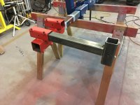
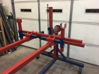
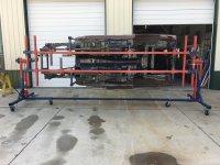
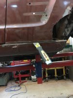
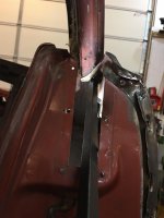
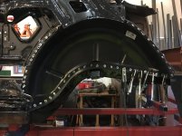
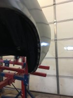
Rear quarter, wheel houses are next. I was concerned that the car, being a structural member, the way I had it mounted in the rotisserie, could tweak if I start removing the quarter and wheel wells so I decided I needed to build a frame jig for the rotisserie to mount the car to. This is what I ended up with. I did this over Christmas break into the first part of January. What I am finding out is the Rustang build was just an excuse to build a rotisserie, frame jig, engine run stand and all the other equipment to become a body man.
Lots of drilled holes in tubes at 45 degrees. 1/2-13 unc hex nut and 1/2-1" bolts. Drilling the holes on the corners really drives the inner tube to the outer tube for a nice, tight, square connection that doesn't slip or wiggle. I highly recommend this way for tube to tube slider arrangement. Watch for the seam on the inside of the female tube and make sure it is adjacent to the corner hole other wise the fit won't be the best. Welding the nuts on the corners can be a little challenging as well. It was worth it but it took some time. This rotisserie might be the best thing I get out of this whole exercise.
Attachments


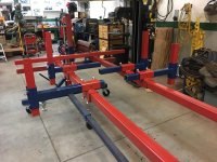
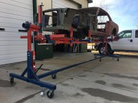
More pictures of the frame jig complete then getting the car back onto the shake and bake stand.
Attachments


AZ Pete
Well-known member
More pictures of the frame jig complete then getting the car back onto the shake and bake stand.
fascinating! Subscribed.
Sent from my iPad using Tapatalk
larry4406
Well-known member
Nice rotisserie!
Any logic to the red and blue colors?
Any logic to the red and blue colors?
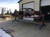
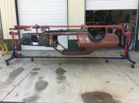
No real logic other than I thought it would lead a person as to how it goes together if it is apart, the details would show better in pictures. I had a bunch of leftover $1 Walmart spray bombs from previous projects and it was 10 degrees in the shop when I painted most of this.
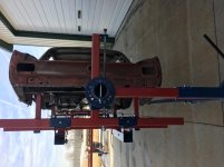
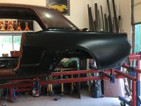
Few more pics of car on rotisserie with frame jig. Connection points are with the leaf spring mounts, front of rocker rails, and front part of the new frame. Nice and rigid with the car body not being stressed. The body now sits about 10” higher on the jig though. Next up, rear quarters and wheel wells. It’s gonna get ugly for a bit....:
Attachments
-
 73536D94-63F2-4FC1-8EA2-E0C4AA409620.jpg148.8 KB · Views: 75
 -
 8BA3D917-53E7-40FC-8066-82D591D1751D.jpg150.4 KB · Views: 74
 -
 295605CD-D8CE-4DAA-913E-5F904267539F.jpg149.4 KB · Views: 75
 -
 3D8C0886-5321-440D-9F28-E307A684C6D1.jpg149.3 KB · Views: 76
 -
 E7A8655D-D460-4CCF-9E9D-95627DEB1FC8.jpg150.7 KB · Views: 77
 -
 9416AA9F-80B0-40FE-A28F-02768E6033E2.jpg149.5 KB · Views: 80
 -
 9B973013-D65A-4B1A-A8F2-E76142ABF111.jpg147.7 KB · Views: 70
ambenz
Well-known member
Amazing rigid jig to mount on the rotisserie...nothing is shifting bending or getting out of wack with that jig!
Thanks for the updates!
Thanks for the updates!
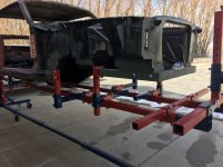
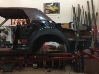
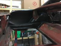
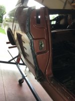
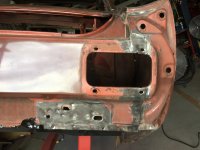
Ready to tear into the rear quarters. Probably the most dreaded part of rust repair work. I've got rust along the outer seam of the wheel well and the rear trunk floor extension pan. Pictures show all the areas that will need broken apart to get the quarter off and expose the inner structure. I am trying to take it off complete to get a better feel for how this will go back together. Put the door on to double check body lines. I marked the door hinge placement so when the new quarter goes on, I will fit it to the door body lines before welding in place.
Attachments


ScottsGT
Well-known member
Dude, you did the cowl already. It was the hardest to do! QP is a walk in the park.
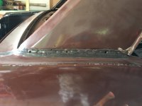
Rear quarter panel removal. The pictures show the connection points that needed to be broken apart. Tools of the trade, strong putty knife, hammer, drill and sharp drill bits. I removed the panel complete to see how difficult it was and to have something to reference when it comes time to go back together.
This car was a vinyl top car originally so the seam with the roof pillar was not leaded in. There is a chrome molding strip that bolts into place. I am contemplating reusing this molding as a conversation point for the mustang purists. Plenty of dolly work will be necessary to reshape the joints as some of the spot welds are impossible to get to with a drill or grinder. MC hammer time on those.
The lip over the rear window inner structure flange was a little bit of a challenge. Long pry bar did the trick with the hammer.
Attachments

pgk
Member
Looks like your coming along nicely on that car, back in the day I had a 1969 fastback with a 428 SCJ, fun car to drive. Although it didn't help my driving record! lol We ended up putting a Built 427 side oiler with medium riser heads and a twin 4 barrel setup in it, wish I still had it 
Pete
Pete
slackdaddy1
Well-known member
I am in the middle of "rebuilding a jeep XJ,, I looked into a couple different "weld bond adhesives" , they are a panel bonding adhesive for pinch seams that can be "spot welded" in addition to the adhesive, giving the seam extreme corrosion protection.
I talked to the engineers (techs) at the companies and they said it was ONLY for resistance spot welding, NOT plug welding with mig or tig.
I guess the resistance welding puts a lot LESS heat into the surrounding metal?
Still looking for the holy grail for pinch seams.
Slack
I talked to the engineers (techs) at the companies and they said it was ONLY for resistance spot welding, NOT plug welding with mig or tig.
I guess the resistance welding puts a lot LESS heat into the surrounding metal?
Still looking for the holy grail for pinch seams.
Slack
Fantastic read and fabulous work! As a person that has performed this type of work for 25 plus years, your work is far superior to more than 90% of the vehicles that I have run across that were modified and repaired in this manor. Your engineering skills and understanding of the materials really shows. I enjoyed how you happened across new ideas and techniques for removing the old parts. The Blair cutters, grinding wheels, cut-off wheels etc. That is knowledge that comes from trial and error experience and a desire to improve.
I have a few ideas that you may like to look into. I only suggest these as they are from learning from failure and learning from others.
As you start the exterior sheet metal stage, I would recommend looking into using a combination of plug welding, stitch welding, solid panel welding in conjunction with a urethane and or epoxy bonding adhesive. The benefits of combining the adhesives with welding are tremendous including corrosion protection and adding strength overall to any area. It's clear that your goal is to overcome many of the short comings of the fabulous Rustang and this process will will help you achieve such. Something else I would recommend is the use of weld-through primer or pre-priming overlapping joints. I also use a lot of **** joints in exterior work often using a backing panel when needed.
I look forward to seeing future progress!
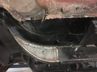
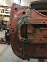
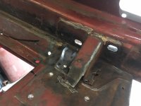
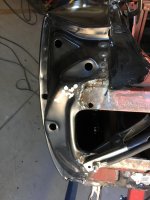
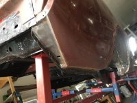
Pictures show the removal of the driver side rear trunk pan extension. First step is to remove the interior bumper support bracket to fully expose the trunk pan extension. Lots of spot welds to drill out, then putty knife and hammer action to get things apart. Wasn't too bad of a job, particularly on a rotisserie. I've got divots to fill in with the welder, clean up the interior of the frame rail, then POR 15 the interior surfaces of the frame rail and internal framing structures before the new metal starts to go on.
This car and most car bodies are built like a quilt. A bunch of small pieces spot welded together in a pattern to create something useful. I guess my 70+ year old mom and I have something else in common now except I SEW WITH FIRE!!!!!
This car and most car bodies are built like a quilt. A bunch of small pieces spot welded together in a pattern to create something useful. I guess my 70+ year old mom and I have something else in common now except I SEW WITH FIRE!!!!!
Attachments


p_mori7
Well-known member
How's the project coming along BG69 ?
Been away helping on the farm some, work has been busy too and then all the normal spring activities pulled my focus away from work on ole rusty crusty.
I got out of sync with a few pictures so trying to get back in sequence.
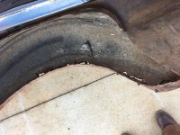
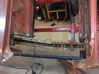
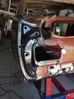
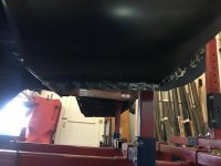
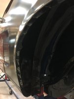
These pictures show the quarter panel removed and all the beauty, rust behind it. Dusted every thing off with wire brushes and sanders the best I could and put POR 15 on all the internal structures before they get covered up.
I got out of sync with a few pictures so trying to get back in sequence.
These pictures show the quarter panel removed and all the beauty, rust behind it. Dusted every thing off with wire brushes and sanders the best I could and put POR 15 on all the internal structures before they get covered up.
Attachments


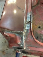
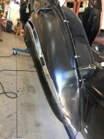
Rear trunk pan installation and wheel well installation start. Traced frame rail onto trunk pan extension, drilled out holes then spot weld in place. Next, fitted up inner and outer wheel house. The inner wheel well fit the inner structure connection points well and the pan flanges. I did also have to rebuild some of the old rear pan flange with some random sheet metal pieces to have something for the inner wheel well to weld too. Every thing "Seemed" to go together well so I started spot welding the 9inner wheel well in. The Harbor Freight throat-less shear is a good buy. I recommend it for the average end user.
Attachments


matt_i
Well-known member
Wow, a lot of work in that rear quarter. Looking very good!  I always wonder how much rust is lurking inside the panels of my old pickup....
I have the Beverly throatless shear and I highly recommend the throatless shear tool, it takes up minimal space and is versatile for so many jobs.
I always wonder how much rust is lurking inside the panels of my old pickup....I have the Beverly throatless shear and I highly recommend the throatless shear tool, it takes up minimal space and is versatile for so many jobs.
ford33
Well-known member
Nice work on that mustang. It's coming together well.
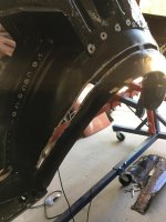
The fitting of the inner and outer wheel houses require them to go into the car individually then finalized on the car as a pair before the quarter goes on. As stated previously, the inner wheel house fit like a glove so presented to the car and partially welded in place..
The outer wheel house nests into the rocker panel at the front and then follow the seem of the inner wheel house around to the back trunk panel extension. Everything looks good. Fitted the quarter to the car to verify fitment to the quarter wheel well lip and that's where I found some troubles with fitment. Ended up having to cut the outer wheel house to pivot the lip down and out by about an 1.25" at the top of the arch to fit the quarter. Took me about a day to sort the outer wheel house out, weld it back up, then put some body filler on it to make it perfect.
I have read on the internet that this sometimes occurs. I did have the right parts. It took me a while to decide to slice up the outer wheel house. It ended up right in the end. Also, before I finally placed the outer wheel in place, I put a bunch of POR 15 into the rocker rail weld-ment on the one end and used a long blow gun to attempt to coat the inside of the rocker rail as best I could. It actually worker pretty well but no pictures to show.
This was the first thing that did not fit up well for me. A little disappointed how it came together in the end but I did my best with what I had to work with.
Attachments


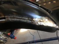
Pictures show the completion of the wheel house assembly on the car then presenting the quarter and getting everything fitted up. All about gently nudging and clamping into place.
Started welding the quarter in place in the rear and will move forward, finishing panel welding at the door pillar, making sure it matches the door panel as I finish up. This part went fairly well without issue.
Started welding the quarter in place in the rear and will move forward, finishing panel welding at the door pillar, making sure it matches the door panel as I finish up. This part went fairly well without issue.
Attachments

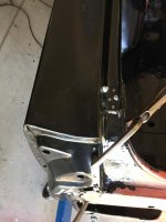

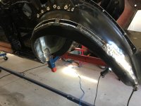
Enclosed are some random pictures of the rear driver side quarter in place. Much better then what was there. For these old Mustangs, the fender well is a major structure item to the rear of the car by tying in the frame rail to the rear roof pillar structure.
Body lines fit well. I decided to weld in fully the joint at the top of the quarter and the center piece bottom of the window. Usually there is an exposed seam.
Will leave the finish work to the rear roof pillar for a little later. Still debating on whether I re-use the chrome accent piece, used for vinyl top cars, to separate with the painted quarter below or fully fill in the holes and leave the molding off. Thought it could be a good conversation point with the Mustang purists out there in the world.
Attachments


BMW Rider
Well-known member
A lot of people (myself included most likely) would have written that car off as too rusted to be worth saving. Great job
p_mori7
Well-known member
Very nice work BG69 !
Thanks for the comments. The car ended up being rustier than I thought it was but I decided to own my mistake and move forward and learn by doing. It's getting easier as I go.
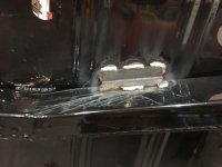
Few last pictures showing the spot welds around the fender lip and rear quarter bottom and back flange. No longer a rookie!
Few last pictures showing the spot welds around the fender lip and rear quarter bottom and back flange. No longer a rookie!
Attachments

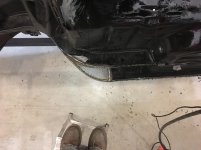
Time to move over to the passenger side for more carnage. I start by taking a right angle grinder with wire wheel and expose all the seams to find the gaps and the spot welds to drill out. Then I use a wide flat brick layer chisel and hammer, long pointed bars or my new friend an air chisel to break things apart. The air chisel makes things happen in a hurry. Noticed on both quarters that there was brass holding some of the joints together. This gives me the idea that may be the quarter might have been replaced once before. Don't know if factory would have done that. The brazing was done in a few spots consistently.
Attachments


The brazing is factory. You'll notice it also on the trunk corner pieces where they meet the quarter and tail light panel, also on the cowl near the windshield posts.
They also used lead where the top of the quarter meets the sail panel from the roof.
They also used lead where the top of the quarter meets the sail panel from the roof.