ScottsGT
Well-known member
I may be late saying this, but did you install the trunk lid and check gaps before welding up? I caught hell with my '66 Fastback by not doing this.

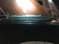
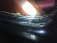
moving from spot to spot in a deliberate manor.
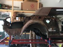
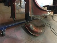
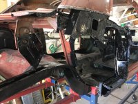
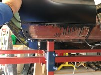
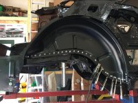
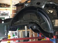
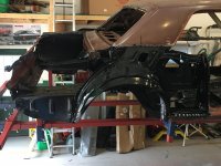
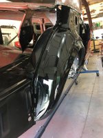
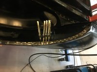
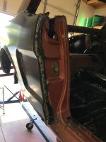
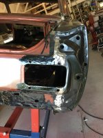
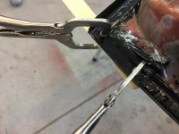
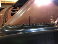
Rear quarter panel removal. The pictures show the connection points that needed to be broken apart. Tools of the trade, strong putty knife, hammer, drill and sharp drill bits. I removed the panel complete to see how difficult it was and to have something to reference when it comes time to go back together.
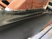
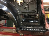
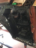
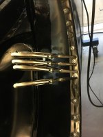
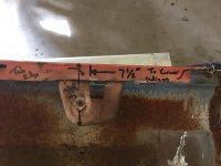
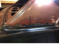
This car was a vinyl top car originally so the seam with the roof pillar was not leaded in. There is a chrome molding strip that bolts into place. I am contemplating reusing this molding as a conversation point for the mustang purists. Plenty of dolly work will be necessary to reshape the joints as some of the spot welds are impossible to get to with a drill or grinder. MC hammer time on those.
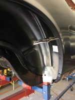
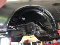
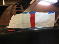
The lip over the rear window inner structure flange was a little bit of a challenge. Long pry bar did the trick with the hammer.
Looks like your coming along nicely on that car, back in the day I had a 1969 fastback with a 428 SCJ, fun car to drive. Although it didn't help my driving record! lol We ended up putting a Built 427 side oiler with medium riser heads and a twin 4 barrel setup in it, wish I still had it
Pete
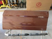
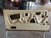
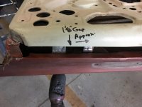
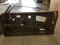
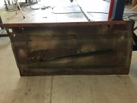
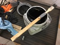
I am ahead of the picture game here but need some advice. Getting ready to put new skins on the doors of the car. Salvaged the old door inner structure and POR 15 on all clean surfaces. The old outer door skins had an undercoating on them on the inside.
What should a person use on the new door skins on the inside? I've looked at the Lizard Skin product but it states that it is more for sound or thermal related issues. Is it a good choice for this and then also for undercoating the car? What would you recommend, what have you used with success?
Thanx.
")
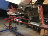
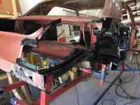
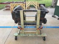
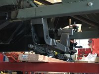
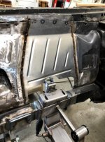
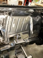
With the MII suspension installed, are the original shock towers going away?
With the MII suspension installed, are the original shock towers going away?
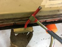
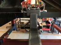
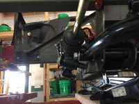
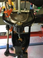
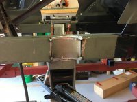
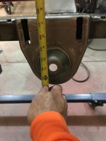
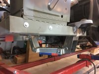
I don't want to de-rail bigguns69's thread. I'm in the middle of installing front and rear R&C suspensions, here's some pics of the front. Yes, no more shock towers.