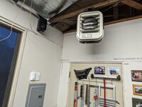
Hi, I took a look through some of the threads for QMark and a couple already helped me with the wiring from the breaker but I have a question on the factory wiring on the control terminal board.
Some quick background on the unit. I got this second hand from my sister-in-law after her husband passed. She said he got it online but not sure from where. No box or manual. They hired someone to install it but he couldn't get it running so they bought a different unit and had that installed with no issue. When I got the QMark I found the install manual online and noticed that someone along the line switched the A1 & B1 wires to three phase. I'm thinking he got this off eBay and it was previously used in a commercial setting. Anyways, I set those back to one phase and got the unit to turn on. That's where I've hit a wall.
The heater is in a detached garage and it's currently 27 degrees outside. 35'ish in the garage. I'm using a single stage thermostat.
When flipping the breaker on, the heater turns on without the thermostat switched to on and the temp is set to the lowest temperature. The heater does not turn off (both heat and fan). I have H1 & H2 jumped per the instructions and am using P1 & H1 for the single stage thermostat connections. In addition, I've tried three brand new thermostats of different models and get the same result. I've also switched the thermostat wires around on the terminals for all three stats.
So to get to my question, I'm wondering if someone changed the A1 & B1 wires for three phase, what else might they have switched on the control terminal board or elsewhere? Comparing what I see on the diagram unit base to how it's wired something looks off. I'm pretty good at following things on a diagram but not an electrician so any help would be appreciated ( throwing some shade if necessary is welcome too ).
).
Or, am I not being patient enough to wait if the heater does turn off after turning the breaker on? I've waited around 5 minutes max.
Pics are below. One curious item is the diagram explicitly states that the power terminal block is for use with copper connectors only. There is one wire I show below that does not match the other wires and what has, I'm guessing, aluminum connectors. I have doubts Marley did that if they stated to use only copper.
Thanks for any input you have - Paul

0521 Diagram

Aluminum connector mentioned above connected to P1. This is the only connection to P1 (P1 -> terminal block).

End location of wire w/ aluminum connector (P1 -> terminal block)

Control Terminal Board w/ thermostat connections
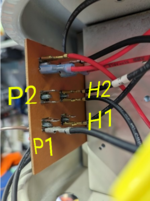
Backside of control terminal board. A1 wire is currently connected to H2 which is jumped to H1. A1 is connected to the terminal block first position.
Also, A1 wire from H2 terminal and wire from P1 are both connected to the same location on the terminal block.

All current wiring
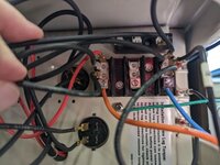
Terminal block connections
Some quick background on the unit. I got this second hand from my sister-in-law after her husband passed. She said he got it online but not sure from where. No box or manual. They hired someone to install it but he couldn't get it running so they bought a different unit and had that installed with no issue. When I got the QMark I found the install manual online and noticed that someone along the line switched the A1 & B1 wires to three phase. I'm thinking he got this off eBay and it was previously used in a commercial setting. Anyways, I set those back to one phase and got the unit to turn on. That's where I've hit a wall.
The heater is in a detached garage and it's currently 27 degrees outside. 35'ish in the garage. I'm using a single stage thermostat.
When flipping the breaker on, the heater turns on without the thermostat switched to on and the temp is set to the lowest temperature. The heater does not turn off (both heat and fan). I have H1 & H2 jumped per the instructions and am using P1 & H1 for the single stage thermostat connections. In addition, I've tried three brand new thermostats of different models and get the same result. I've also switched the thermostat wires around on the terminals for all three stats.
So to get to my question, I'm wondering if someone changed the A1 & B1 wires for three phase, what else might they have switched on the control terminal board or elsewhere? Comparing what I see on the diagram unit base to how it's wired something looks off. I'm pretty good at following things on a diagram but not an electrician so any help would be appreciated ( throwing some shade if necessary is welcome too
).Or, am I not being patient enough to wait if the heater does turn off after turning the breaker on? I've waited around 5 minutes max.
Pics are below. One curious item is the diagram explicitly states that the power terminal block is for use with copper connectors only. There is one wire I show below that does not match the other wires and what has, I'm guessing, aluminum connectors. I have doubts Marley did that if they stated to use only copper.
Thanks for any input you have - Paul
0521 Diagram
Aluminum connector mentioned above connected to P1. This is the only connection to P1 (P1 -> terminal block).
End location of wire w/ aluminum connector (P1 -> terminal block)
Control Terminal Board w/ thermostat connections
Backside of control terminal board. A1 wire is currently connected to H2 which is jumped to H1. A1 is connected to the terminal block first position.
Also, A1 wire from H2 terminal and wire from P1 are both connected to the same location on the terminal block.
All current wiring
Terminal block connections