To avoid these ads, REGISTER NOW!

Quad box ground

bluedog225

Well-known member
Joined
Jan 31, 2012
Messages
3,353
Location
Texas
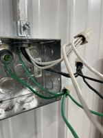
What do y’all prefer for grounding a metal quad box? A single long, ground half flipped around each plug ground and then to the box? Or a pigtail with leads coming off to the plugs and box? Wire nut or just twist them?

Whichever one I use seems a little hacked together. Thought I’d check with the experts.

Thanks
 
To avoid these ads, REGISTER NOW!

Snapped-off

Well-known member
Joined
Feb 22, 2012
Messages
4,827
Location
Indiana
Pigtail off the incoming ground feed to the box, with more pigtails to any receptacles.

Use your imagination.
1000024149.jpg
Sketch not to scale.
 

JohnX14

Well-known member
Joined
Jun 2, 2014
Messages
630
Location
Boston 'burbs
I'd wrap the ground screw and assuming there are multiple cables in it I'd then splice all the bares or greens (stripped) using a Splice Cap (crimp sleeve) and leave a conductor beyond the splice cap for each receptacle. Granted grounding receptacles are legal, but I'd put the pigtail as well. If it is a single grounding conductor, and if it is solid, I'd wrap the ground screw then hit each receptacle all with one conductor. If it is stranded conductors, I'd do it exactly like post #2.
 

Snapped-off

Well-known member
Joined
Feb 22, 2012
Messages
4,827
Location
Indiana
I'd wrap the ground screw and assuming there are multiple cables in it I'd then splice all the bares or greens (stripped) using a Splice Cap (crimp sleeve) and leave a conductor beyond the splice cap for each receptacle. Granted grounding receptacles are legal, but I'd put the pigtail as well. If it is a single grounding conductor, and if it is solid, I'd wrap the ground screw then hit each receptacle all with one conductor. If it is stranded conductors, I'd do it exactly like post #2.
I've got a bunch of EC motors where they wrapped the stranded ground on install and it just destroys the wire.

Most of them I find when replacing a motor, the ground wire is broken into two pieces.
1000024008.jpg
 
OP
B

bluedog225

Well-known member
Joined
Jan 31, 2012
Messages
3,353
Location
Texas
I didn’t know about self grounding stuff. I guess another alternative is spade terminals for the stranded.

Thanks all.
 

sparky 1971

Well-known member
Joined
Oct 9, 2018
Messages
8,078
Location
Central Iowa
If I'm using a metal box, then I'm probably using EMT and not pulling a ground at all. If for some reason a ground wire is present because I've used Romex, MC cable, PVC, or someone else did it, I will bond it to the box and I'm done. No grounds are getting connected to the receptacle.
 

JohnX14

Well-known member
Joined
Jun 2, 2014
Messages
630
Location
Boston 'burbs
I've got a bunch of EC motors where they wrapped the stranded ground on install and it just destroys the wire.

Most of them I find when replacing a motor, the ground wire is broken into two pieces.
1000024008.jpg
I was referencing solid conductor around the screw, not stranded.
 

JohnX14

Well-known member
Joined
Jun 2, 2014
Messages
630
Location
Boston 'burbs
If you're using stranded, strip the wire but leave the stripped insulation on the end of the wire. It will keep everything together so the strands don't fray apart.
Another trick, whether leaving the insulation on the end or not, is to 'twist' the group of strands counterclockwise. The screw tends to tighten the twist rather than separating them. Although I'll generally use a solderless terminal, unless I'm in a hurry or a bind. I generally don't wrap stranded conductors.
 
To avoid these ads, REGISTER NOW!

sparky 1971

Well-known member
Joined
Oct 9, 2018
Messages
8,078
Location
Central Iowa
To go to the next box?

What am I missing? (Pretty sure I know ;) )
There has to be a junction box before the box in the photo. Make the splices in that box with one set going to the devices. There's nothing wrong with the way it's done in the photo other than using a bunch of extra wire, I've just never seen it done that way. Might as well have a conduit in and another out of the box shown and eliminate the box not in the photo. It does save a couple of wire nuts though, and those tan twisters are getting pricey. I just bought a jar of 400 for $60.
 

PCustoms

Well-known member
Joined
Jul 23, 2011
Messages
23,692
Location
VT
There has to be a junction box before the box in the photo. Make the splices in that box with one set going to the devices. There's nothing wrong with the way it's done in the photo other than using a bunch of extra wire, I've just never seen it done that way. Might as well have a conduit in and another out of the box shown and eliminate the box not in the photo. It does save a couple of wire nuts though, and those tan twisters are getting pricey. I just bought a jar of 400 for $60.
Kind of begs the question, what's at the top of that vertical conduit? Doesn't it...
 

Mainiac Mat

Well-known member
Joined
Sep 2, 2020
Messages
407
Location
Maine
Pigtails....
This little piggy went to the ground screw on the box
These little piggy went tot he ground termimal on the outlets
And the last little piggy cried wee-wee-wee all the way back to the load center.
🙃
 

mike93lx

ALLIANCE MEMBER
Joined
Dec 9, 2013
Messages
38,223
Location
Richmond, VA
There has to be a junction box before the box in the photo. Make the splices in that box with one set going to the devices. There's nothing wrong with the way it's done in the photo other than using a bunch of extra wire, I've just never seen it done that way. Might as well have a conduit in and another out of the box shown and eliminate the box not in the photo. It does save a couple of wire nuts though, and those tan twisters are getting pricey. I just bought a jar of 400 for $60.
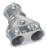
Since speculating is fun, my vote is that there is one of these just above the picture

1745946531948.jpeg
 

u2slow

Well-known member
Joined
Nov 20, 2011
Messages
3,622
Location
BC
I take the longest incoming bare bond wire and wrap it on the box screw, and then into a wire nut with all the rest.

Sometimes I daisy-chain one tail across two receptacles before going to the wire nut.
 

sparky 1971

Well-known member
Joined
Oct 9, 2018
Messages
8,078
Location
Central Iowa
I was going to say the same, but I figured some pro would hoping and say "seriously, how do you not know about these!"
Those look to me like they are made for someone that likes to work harder than they have to. Stripping off a mile of jacket, then trying to shove two sets of that twisted **** they call MC down a piece of EMT doesn't seem like a fun way to waste time.
 

u2slow

Well-known member
Joined
Nov 20, 2011
Messages
3,622
Location
BC
Those look to me like they are made for someone that likes to work harder than they have to. Stripping off a mile of jacket, then trying to shove two sets of that twisted **** they call MC down a piece of EMT doesn't seem like a fun way to waste time.

That's a common transition for concrete suspended slabs. You have a ceiling box cast into the concrete, and there's an EMT stub-down for it at the nearest planned stud wall.
 

onewheat

Well-known member
Joined
Feb 19, 2012
Messages
1,286
Location
Knoxville, TN
Why are there two hots and two neutrals from the same circuit in the conduit?
To go to the next box
To go to the next box?

What am I missing? (Pretty sure I know ;) )
Correct - and I'm not sure?
There has to be a junction box before the box in the photo. Make the splices in that box with one set going to the devices. There's nothing wrong with the way it's done in the photo other than using a bunch of extra wire, I've just never seen it done that way. Might as well have a conduit in and another out of the box shown and eliminate the box not in the photo. It does save a couple of wire nuts though, and those tan twisters are getting pricey. I just bought a jar of 400 for $60.
There is a 60' run, 8' off the ground with a junction box every 10' and a 4' drop to double gang outlets - the boxes alternate what circuit they're on. The splice could have been in the 8' junction box saving 4' or wire at every drop, I guess. Is that what you're saying? That's the way it was run. :dunno:
Kind of begs the question, what's at the top of that vertical conduit? Doesn't it...

A junction box

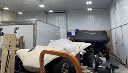
garage electric.jpg

The right side wall - you can see the conduit and a few of the drops. It's the way the electrician pulled the wire.
 

dscheidt

Well-known member
Joined
Apr 26, 2017
Messages
2,918
I didn’t know about self grounding stuff. I guess another alternative is spade terminals for the stranded.

Thanks all.

Self grounding means that one of the mounting ears has a brass contact spring for the mounting screw. That assures that device is making good contact with the screw. The screw is, one hopes, screwed into a metal box that's grounded. They're nearly universally in metal conduit installations, because it saves much time terminating devices, and saves the wire, and the boxes are neater. To meet code requirements on exposed work boxes, you need to use an exposed work cover with recessed corner screws, and use real serrated nuts on the device mounting screws, not the stupid break-off tabs built in to new covers. Also, the plastic or cardboard insulator retaining thing on the screw has to be removed.
 

sparky 1971

Well-known member
Joined
Oct 9, 2018
Messages
8,078
Location
Central Iowa
To go to the next box

Correct - and I'm not sure?

There is a 60' run, 8' off the ground with a junction box every 10' and a 4' drop to double gang outlets - the boxes alternate what circuit they're on. The splice could have been in the 8' junction box saving 4' or wire at every drop, I guess. Is that what you're saying? That's the way it was run. :dunno:


A junction box

garage electric.jpg

The right side wall - you can see the conduit and a few of the drops. It's the way the electrician pulled the wire.
Just for fun, could you post more pictures? The top and bottom box while still showing a bit of the conduit as well as both in the same photo but closer than in this picture. I'm curious about what in the world is going on. It appears that the conduit comes straight down from the top box and is supported by a minnie clamp, but has a backwards box offset to get into the bottom box. I want to tell myself that can't be and there is something out there I'm not familiar with. Or, my eyes are playing tricks on me...again.
 

mm08822

Well-known member
Joined
Jan 13, 2012
Messages
6,113
Location
NJ
I see it too, now that you mentioned it.

Depending on the rib spacing and depth, it could require a little planning to minimize offsets. Even a painted 4x4 spacer under the upper boxes to eliminate offsets into them would be helpful. Single 1 hole straps on the horizontals would be simple.

I would not want to be adding cowboy straps on the verticals, just use a 1 hole strap.
 

sparky 1971

Well-known member
Joined
Oct 9, 2018
Messages
8,078
Location
Central Iowa
I see it too, now that you mentioned it.

Depending on the rib spacing and depth, it could require a little planning to minimize offsets. Even a painted 4x4 spacer under the upper boxes to eliminate offsets into them would be helpful. Single 1 hole straps on the horizontals would be simple.

I would not want to be adding cowboy straps on the verticals, just use a 1 hole strap.
That might be it, but if it's in a minnie on the way down, it should line up perfectly with an existing ko.

Not many people know about them, but Raco has made a box for this application. Part number 232CS. CS stands for corrugated steel and on two sides opposite each other, the ko's are punched a little farther out, allowing the conduit to lay on top of the ribs with no offsets or spacers needed. The other two sides are the standard location. Run the pipe horizontal across the ribs using one hole's, set a box and go straight down (or up) to another box. I've started using Caddy 812M's for straps on the verticals. The little bastards are expensive, but there's no screwing around with the bolt when it comes to minnies or box offsets.

 
Last edited:
To avoid these ads, REGISTER NOW!
Top Bottom