To avoid these ads, REGISTER NOW!

Question about bench grinder motor windings

pwinters

Active member
Joined
Aug 5, 2020
Messages
37
Location
Chicago
I am fixing up a 1/2hp Craftsman bench grinder (397.19440) from the 70s(?).

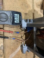
I tried wiring it up this evening and nothing happened. Using my multimeter, I get about 7ohms resistance across the start winding and run winding hot leads, but I’m getting infinite resistance between run and common and start and common. On amps setting, I can see mA being generated when I have the start and run leads hooked up to the multimeter and I spin the rotor inside the stator.

Does it make sense that I can get an ohm reading across start and run but an open circuit when I do run and common start and common? What would be the next thing to test?

(I bought a new start cap and went with a new universal potential relay, so it probably isn’t the peripheral components of the circuit. The switch tested out fine as well.)
 
To avoid these ads, REGISTER NOW!

walta

Well-known member
Joined
Jan 13, 2017
Messages
2,313
Location
Dutzow Missouri
I think I need you to post a few photos because your words are not making sense to me.

What do you mean when you say “common”?

Wild guess is there is an overload protector in the circuit that is open.

Walta
 
OP
P

pwinters

Active member
Joined
Aug 5, 2020
Messages
37
Location
Chicago
I don’t think there is an overload protector. I took apart the entire circuit (someone had already rewired once before). There are four wires coming from the windings. Here are a few pictures of the various combinations.
 

Attachments

  • B09D76B9-9EA3-4693-BA2F-8C7B28C4AC85.jpeg
    B09D76B9-9EA3-4693-BA2F-8C7B28C4AC85.jpeg
    350 KB · Views: 45
  • 7A61D772-7B24-4BCD-BE0E-85DDCAA19118.jpeg
    7A61D772-7B24-4BCD-BE0E-85DDCAA19118.jpeg
    402.2 KB · Views: 34
  • BC90BD45-D88C-4E24-A618-605398D088F8.jpeg
    BC90BD45-D88C-4E24-A618-605398D088F8.jpeg
    397.6 KB · Views: 32
  • CEFB7F8E-DE5A-4AF9-A720-05A3C120B012.jpeg
    CEFB7F8E-DE5A-4AF9-A720-05A3C120B012.jpeg
    393 KB · Views: 32
  • CFAA05D0-7C6C-4E42-ACEA-97AACD806463.jpeg
    CFAA05D0-7C6C-4E42-ACEA-97AACD806463.jpeg
    402.7 KB · Views: 44

Lightning rod

Well-known member
Joined
Dec 1, 2012
Messages
283
Location
Toronto , Ontario

walta

Well-known member
Joined
Jan 13, 2017
Messages
2,313
Location
Dutzow Missouri
It seems you are missing some important parts like a starting relay and or a capacitor.

If this wiring diagram is correct for your grinder and it may very well not be the correct one.

I recall seeing similar grinders with a large strangely shaped square capacitor in the base

Walta
 

Attachments

  • 7-28-2021 10-40-16 AM.jpg
    7-28-2021 10-40-16 AM.jpg
    9 KB · Views: 66
OP
P

pwinters

Active member
Joined
Aug 5, 2020
Messages
37
Location
Chicago
What is the resistance value across the two black wires
looks like the rewire brings out the wires independently for the two windings
so you will get a resistance value between black wires and white wires
but not between the sets in this setup

see the wiring diagram in this document , not exactly your model , but it should work

Thanks for linking to the manual. That is actually my model. So, it is 1.1 ohms across the two black wires. What does that mean? Shouldn’t I get readings between white and black? Instead, all I get are readings across the two whites and across the two black wires.

Do you think this motor has been rewired? I guessed that at least the relay had been changed out with a solid state switch and maybe the start cap was replaced? I have a new start cap and I ended up buying a universal potential relay that takes the start winding out of the circuit in a set amount of time (under 1 sec, I think).

Can you help me figure out how to translate the wiring diagram in the manual to my four lead wires coming off the windings?
 

Lightning rod

Well-known member
Joined
Dec 1, 2012
Messages
283
Location
Toronto , Ontario
pwinters
Sounds like you have two perfectly functioning windings
Can you please confirm which model you have? You mentioned 440 and I included the 441 manual
The 441 manual has no capacitor in the circuit.
Was there a capacitor installed in the grinder when you got it? Or was it in a box of parts?
When you say you wired it up, is that because the wires were all disconnected ?
 
To avoid these ads, REGISTER NOW!
OP
P

pwinters

Active member
Joined
Aug 5, 2020
Messages
37
Location
Chicago
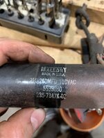
Sorry, I got confused. I have a 441 with the start capacitor. I am including some pictures of the solid state switch and start capacitor that came with the grinder. I had wanted to start with new components, thinking these were probably at the end of their useful life and I was pretty sure these were after market items (since the power cord was two prong instead of three and the diagram seemed to call for a current relay rather than a solid state switch).

So, I bought a 216-260mfd/330v cap and a Supco universal potential relay with the 1,2,5 terminals. I guess I am in over my head with the wiring, not sure which of the four wires go where. I thought I could just disconnect everything and start fresh. I didn’t document the original wiring since I had different components and I didn’t trust how it was wired. I thought the two orange cloth wires go to the line side of the circuit and the two black are common or neutral side but am obviously confused now. Appreciate any help you can provide in getting this wired correctly. I can use the old components if they would be better.
 

Attachments

  • 395C6C9D-1F80-4E1E-AB81-A0ABB53EBAEA.jpeg
    395C6C9D-1F80-4E1E-AB81-A0ABB53EBAEA.jpeg
    416.2 KB · Views: 48
  • 7FF202B1-7E4C-4935-B799-0AE47C5009F5.jpeg
    7FF202B1-7E4C-4935-B799-0AE47C5009F5.jpeg
    237.7 KB · Views: 33
  • EF6059AA-11CB-45C0-80AD-F328D8837741.jpeg
    EF6059AA-11CB-45C0-80AD-F328D8837741.jpeg
    233.2 KB · Views: 25
  • E37E8524-7118-48BD-BEEE-B2FF7FE5ADEE.jpeg
    E37E8524-7118-48BD-BEEE-B2FF7FE5ADEE.jpeg
    437.7 KB · Views: 29
OP
P

pwinters

Active member
Joined
Aug 5, 2020
Messages
37
Location
Chicago
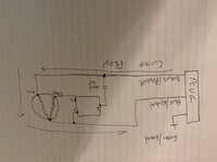
Does this schematic make sense? If so, where do the four wires coming from the winding go?
 

Attachments

  • 03AFF392-9D2B-4E92-87C8-9C01491272E7.jpeg
    03AFF392-9D2B-4E92-87C8-9C01491272E7.jpeg
    109.6 KB · Views: 44

Lightning rod

Well-known member
Joined
Dec 1, 2012
Messages
283
Location
Toronto , Ontario
pwinters
Ok, so you have a 440 model with capacitor
No worries , I have done what you describe many times in my excitement to tear into things
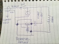
In principle your sketch is correct. I cannot comment on your color of wires since I am a little color blind
I also include a sketch I use that mimics yours but shows the relay function
good luck
let us know how it works out
 

Attachments

  • IMG_0799.JPG
    IMG_0799.JPG
    228.3 KB · Views: 44
OP
P

pwinters

Active member
Joined
Aug 5, 2020
Messages
37
Location
Chicago
Thanks, let me work on implementing your drawing. I imagine being color blind, even a little, makes wiring more difficult! In the first picture I posted back at the beginning of the thread there are four wires coming from the windings—two with thick insulation and two skinny. Do you know which each one is?
 
OP
P

pwinters

Active member
Joined
Aug 5, 2020
Messages
37
Location
Chicago
It works! I wasn’t understanding the ohm readings and what you were saying about the wires going to each winding separately. The two skinny and the two fat wires are each the leads for the two windings. They same wires are pairs. I am thrilled. Thank you!!!
 
To avoid these ads, REGISTER NOW!
Top Bottom