To avoid these ads, REGISTER NOW!

Question on mini-split line set install

crazybrit

Well-known member
Joined
May 29, 2013
Messages
341
Location
Portland, OR
I just bought a Pioneer 12k BTU mini split to install in my shop.

What I'd like to do is run the lineset through the wall at ground level behind the exterior unit and then vertically inside the wall cavity up to the interior unit. However it's 2x4" construction not 2x6". Pioneer recommends a 4" bend radius.

I watched this video showing the bending of the line:
and I think it should be possible but I'm not sure if there are other issues I need to consider?

Obviously plan B is to install on the outside of the wall and then hide with a plastic lineset cover.

Some more details

-------------------------------------------------------------------------------------

The outside condenser unit will be installed directly on the other side of the exterior wall from the head unit. So the only significant distance will be the vertical run.

It's a 7' interior ceiling height and Pioneer recommended mounting the interior unit 6" below the ceiling.

The outside unit will be 14" from the exterior siding.

I purchased 10' of line set.

The interior walls of the shop are OSB, with R11 insulation installed (I guess installed long ago when R11 was "good"). I can easily cut out a section of the OSB from the inside to route the lineset up inside the wall.
 
Last edited:
To avoid these ads, REGISTER NOW!

Jackfre

Well-known member
Joined
Dec 26, 2010
Messages
4,425
Location
N CA
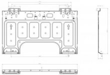
I’m not sure how Pioneer makes their mounting bracket. You end up with thee semi-ciclre cut out at each lower corner, but do they have the lower center potion open as well? If so I would suggest you use that center section.
I ran one of my minis in wall and it was a *****, a real *****. You have to maintain the insulation on each section of the line set or it will sweat in the wall. I ended up having to re-insulate a portion of it with thinner insulation. You then come to the main event. The drain line which is critical that it be run evenly to drain the unit. Oh, and mine was in a 2x6 wall. I can hear Justin and the guys who do this all the time chuckling at me, but you will be much happier having the line set run up the outside of the wall. Also, use a toggle bolt at each corner of the line set. They used to make the mounting brackets our of metal. I think they are tin foil now and when you try to close the unit down onto the bracket you can lever the top away from the wall, at which point you have to then dismount the evap and install toggles. Damn, see now I’m still PO’d. Good luck with it.
 
OP
C

crazybrit

Well-known member
Joined
May 29, 2013
Messages
341
Location
Portland, OR
I’m not sure how Pioneer makes their mounting bracket. You end up with thee semi-ciclre cut out at each lower corner, but do they have the lower center potion open as well? If so I would suggest you use that center section.

Attached is the bracket.

You have to maintain the insulation on each section of the line set or it will sweat in the wall.
Hopelessly naïve question perhaps but can't you just keep the insulation on the pipe around the 90 bend? i.e maintain the single piece of insulation around the tubing as it is now?

The drain line which is critical that it be run evenly to drain the unit.

Does the drain line need to be run with the lineset? I assumed it could just be far shorter and exit the wall, at a slight down slope, higher up on the exterior wall.
 

Attachments

  • bracket.jpg
    bracket.jpg
    19.3 KB · Views: 65

metlmunchr

Well-known member
Joined
Sep 10, 2011
Messages
1,281
I've got a 9K 19 SEER Pioneer I'm planning to install in my den later this week. It uses the same evaporator wall bracket as the 12K 19 SEER unit. The hole to go thru the wall is well outside the width of the bracket since the bracket is somewhere around 10" narrower than the wall unit.

IMO, the instructions about a minimum 4" bend radius on the ref tubing is aimed at DIYers who may attempt to hand bend the tubing rather than use a tube bender. Since the units use 1/4 OD and 3/8 OD tubing, there's no question that the tubing can be bent plenty tight to fit within a 3.5" deep wall cavity.

Looking at the front of the unit, the piping is at the right hand side. Since you plan to open the interior wall, you can swing the tubing around, put the bends in it to get it headed downward within the wall, and have enough length below the unit to make the connections to your tubing package in an area that's open enough to provide unrestricted access for making up and applying torque to the fittings. IMO, this is far easier than attempting to make the connections within the cramped space on the back side of the unit, and provides good access for leak checking once all the refrigerant connections are made.

I would recommend keeping the bend radii as large as practical. Not because the copper can't safely be bent tighter, but because foam pipe insulation tends to deteriorate faster over time at sharp bends as compared to straight runs and more gentle bends. The outside of the curve is stretched, and the tighter the bend, the more the stretching. When the refrigerant piping is within a wall, maintaining integrity of the insulation over time is of paramount importance.
 

KenC

Well-known member
Joined
Dec 20, 2009
Messages
2,604
Location
oklahoma
About in wall tube insulation: I did one last year and was concerned about that too. For better or worse, my solution was foam-in-a-can, liberally applied encasing the original tube insulation and an added 4-6 inches on either side and filling the cavity from sheetrock to sheathing.
 

tdkkart

Well-known member
Joined
Jun 17, 2006
Messages
6,887
Location
Eastern Iowa
I'd be concerned about in-wall enclosure of the line-set, any condensation on the lines will be trapped inside the wall.
 
To avoid these ads, REGISTER NOW!

justinjoyal

Well-known member
Joined
Apr 30, 2015
Messages
888
Location
Quebec
Disclaimer : I have no drawing skills.

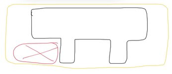
In black is the mounting plate, in yellow the actual unit and in red the hole you should make. Cut it as wide as you can to give your more room to bend the lineset.

Use pre-insulated lineset and make sure the insulation is not punctured to avoid condensation dripping into the wall.

You can insulate both lines together in one larger armaflex insulation tube for the part that’s behind the wall unit, starting where it exits the wall. For example, if the lines are 1/4 and 1/2, slide them both in a single 5/8 armaflex. Make sure to use insulating tape where the armaflex meets the pre-insulated part.

The thinner insulation between the wall unit and the wall allows for easier hanging of the unit on its bracket. Often if you keep both lines individually insulated, plus the drain line and the wire, the bundle becomes quite large and it gets hard to have the wall unit sit flush with the wall because of it.

Use a stainless steel clamp and pvc glue to secure the drain lines together and avoid any future mess.

b4f8d98792113ebfe91739eba6231bec.jpg
 
OP
C

crazybrit

Well-known member
Joined
May 29, 2013
Messages
341
Location
Portland, OR
@metlmunchr how did your install go.

Mine got derailed by other projects.

I'm sure I could muddle through the line set install but I figure it's better if I ask some advice.

So I purchased a WYS012GMFI19RL-16 (12,000 BTU 19 SEER 230V). I selected the 10ft lineset.

My plan is to route the lineset inside the wall cavity (true 4" stud gap) which Pioneer said was fine as the lines are insulated as is the wall (fiberglass batt). The interior walls are OSB so cutting a (large) piece out to aid install and reinstalling is fine and is probably my plan.

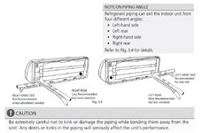
Before I ordered I'd read the beginning of the instructions which said you could cut the hole either to the left side or the right side of the interior mounting plate and had assumed that the connection point behind the interior unit was centered.

This turns out to be wrong.

Attached are some pics.

When I did my measurement I guestimated that using a right side hole would mean I'd be close to the 10ft lineset length and wouldn't need to cut anything. Left side install I'd have excess length.

But looking at the instructions and the back of the unit, you need to bend the built in hoses outwards to do a right side. Pioneer recommends not bending them and doing a left side install. The "most recommended but less common" and "less recommended by most common" verbiage seems odd. If something is recommended over something else, you would think it would be more common.

The left side exit looks simpler as (despite the picture in the manual) no bending of the built in lines is needed, I'd just connect behind the unit? But I'd for sure have excess lineset and Pioneer recommended against coiling it inside the wall. Rather they said I should cut and reflare.

It's possible I'd have to cut and flare the lines if I did the right side anyways as my measuring hasn't been exact.

I'd welcome the advise of those more experienced than I about the best approach.

Also I don't have a flare tool. Pioneer recommended the one they sell but I see quite a few on Amazon also.

I realize the above is a big vague/hand wavy. Sorry.
 

Attachments

  • mounting plate.jpg
    mounting plate.jpg
    77.6 KB · Views: 34
  • left-rear-exit.jpg
    left-rear-exit.jpg
    161.2 KB · Views: 45
  • IMG_20210927_105712476_edit.jpg
    IMG_20210927_105712476_edit.jpg
    526 KB · Views: 40
  • IMG_20210927_105745601_edit.jpg
    IMG_20210927_105745601_edit.jpg
    170.3 KB · Views: 38
  • IMG_20210927_094941216_HDR.jpg
    IMG_20210927_094941216_HDR.jpg
    202.9 KB · Views: 44

metlmunchr

Well-known member
Joined
Sep 10, 2011
Messages
1,281
I found it very easy to swing the lines out and run them into the wall at the right side. This puts the connections to the line set out where they're easily accessible, whereas you have to swing the unit out away from the mounting bracket and prop it in place to get to the connections if you leave the lines in the shipping position and run them thru the wall at the left end. I wanted good access for both tightening the flare connections and for leak checking during the pressure test, and going out at the right hand end was the best way to get there IMO. Also, the insulation on the lines at the unit is split as shipped, and this gave better access for taping and sealing that part of the insulation once the joints were tested.

Re the flares, I cut them off both ends of the line set and re-flared them. In 20+ years in the HVAC business, I never saw a flare on copper tubing that looked like the factory flares on the line set. They were so large that the nuts would barely slip over them, and looked more like they were trying to make the end of a bugle rather than a proper flare.

My Ridgid eccentric flaring tool was at my business shop, so I made the flares with an old school Blackhawk flaring set I've owned since the late 60's. Small diameter soft copper tubing doesn't require high zoot flaring tools to make good flares. Pioneer's installation instructions show the correct height to set the tubing above the flare block, and if you follow those instructions, you'll end up with proper flares and you'll see immediately that they look quite different from the original flares on the line set. I can't say the original flares wouldn't seal, but, from experience, I can say the correct flares absolutely will seal properly so long as the nuts are tightened as specified. From my point of view, it was an easy call to cut 'em off and remake them.

If you need a tubing cutter, I'd recommend one of the Ridgid close quarters cutters over any standard design cutter. Several are available on Amazon from about $14 to $26 depending on max diameter capacity. The close quarters cutter will work in tight spots as well as wide open spaces, while a standard cutter will require more clearance than you may have available in many instances.
 
OP
C

crazybrit

Well-known member
Joined
May 29, 2013
Messages
341
Location
Portland, OR
I found it very easy to swing the lines out and run them into the wall at the right side. This puts the connections to the line set out where they're easily accessible, whereas you have to swing the unit out away from the mounting bracket and prop it in place to get to the connections if you leave the lines in the shipping position and run them thru the wall at the left end.

@metlmunchr I thought about it yesterday and came to a similar conclusion.

I assume you bent the lines in the head unit so they pointed directly out from the back and then made a 90 degree bend so they pointed down in the wall cavity.

Yes, this has the clear advantage that you can then mount the head unit onto the wall (and presuming you've cut the wall open) easily connect the lineset to the head unit lines inside the wall.

If I go with a left side install then I need to run the lineset inside the wall, do a 90 bend to get it out of the mounting hole, then another 90 bend so it can connect in the back of the head unit which as you say is hard as you then have to figure out a way to support the head unit.
 

metlmunchr

Well-known member
Joined
Sep 10, 2011
Messages
1,281
I actually ran mine directly thru the wall and made the turn downward on the exterior. I bought Pioneer's line cover kit which I found to be very good quality for 45 bucks. Bought some spray semi gloss Rust-Oleum suitable for plastic that matched the color of the wood siding and painted all the cover parts before I started the installation so they'd have plenty of time to dry. My indoor section is mounted on a finished wall in a den, so I didn't want to create a repair job involving twice the work of the installation, hence the decision to run down the exterior.
 

Syberia

Well-known member
Joined
Jan 13, 2014
Messages
1,451
Location
Perris, CA
This is the same way I did both of mine, if you come straight back, the connections are outside the wall. Instead of buying the pre-made lineset cover (in my experience, exterior plastic doesn't hold up to the sun), I used 3x4 metal downspout as a lineset cover and it worked perfectly. Cut the back out with an angle grinder and it slid right over everything.

After kinking the lines on my first mini split and having to cut out the kink and replace with a flared elbow, I bought a cheap set of bending springs on Amazon and had no issues on the second.
 
OP
C

crazybrit

Well-known member
Joined
May 29, 2013
Messages
341
Location
Portland, OR
This is the same way I did both of mine, if you come straight back, the connections are outside the wall. Instead of buying the pre-made lineset cover (in my experience, exterior plastic doesn't hold up to the sun), I used 3x4 metal downspout as a lineset cover and it worked perfectly. Cut the back out with an angle grinder and it slid right over everything.

After kinking the lines on my first mini split and having to cut out the kink and replace with a flared elbow, I bought a cheap set of bending springs on Amazon and had no issues on the second.

I need to think about it. It's visible from our back patio so I prefer the idea of it being installed inside the wall cavity but obviously that's more work.

I have one of these tubing benders and also a set of bending springs. Not sure what is best. I was going to buy some scrap tubing of same OD/ID as the lineset and practice first.

Just need to figure out what flaring tool to buy. I think I have a close quarters cutting tool already, need to check.

Thanks for the advice. Much appreciated. This is my first time doing anything like this so I'm trying to measure five times and cut once.
 
To avoid these ads, REGISTER NOW!
Top Bottom