To avoid these ads, REGISTER NOW!

Question wiring t5 lights.

Skdrcr23

Active member
Joined
Jul 29, 2015
Messages
40
I have some t5 lights that I plan on wiring in my
detached accesory building. I have six of them total
that I plan on running on 3 switches of 2 so I can save
on energy and just use 2 of them at a time. My first
question is should I be fine running all of them on the
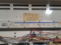
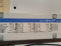
same 20a circuit? My second question is on the wiring
coming out of the lights. They have 3 wires and a spot for
a ground screw I will show in the picture below. Do I need to run a 4 wire system to them with 2 hots, a neutral
and a ground to wire correctly? Would I need a double
pole 20a circuit breaker for the 2 hots?
thanks for the info!
 

Attachments

  • 20160511_195457.jpg
    20160511_195457.jpg
    145.7 KB · Views: 63
  • 20160511_195531.jpg
    20160511_195531.jpg
    140.1 KB · Views: 51
To avoid these ads, REGISTER NOW!
OP
S

Skdrcr23

Active member
Joined
Jul 29, 2015
Messages
40
I couldn't find a wiring diagram on the ballast
anywhere. it's just 3 wires coming out and then
a spot on the bracket for a ground screw
 

matt_i

Well-known member
Joined
Mar 14, 2008
Messages
10,725
Location
SE Michigan
About the first, assuming 120vac, you have 54W/tube x 4 tubes/fixture x 6 fixtures = 1296W = 1300W. Roughly 11A draw on your circuit.

Not sure how lights are wired, unless its something special where there are two ballasts and half of the fixture can be turned on at once, or two ballasts in parallel. Would have to open them up to understand more, as mentioned above.
 

UpNorther

Well-known member
Joined
Jan 20, 2016
Messages
318
Location
Brainerd, MN
Really need a picture of ballast like Klassenl said above.

My guess is 2 - 120v ballasts and there is Inboard/Outboard lighting. So can switch outside tubes independently from inside tubes already.
Yes, 1 - 20amp circuit would be fine.
 
OP
S

Skdrcr23

Active member
Joined
Jul 29, 2015
Messages
40
The way they were wired up at our shop, the light didn't turn on independently of each other when was powered up all four lit up. I'll try to take the fixture to where I can get to the actual ballast and send a picture
 

Cmreschke

Well-known member
Joined
Feb 15, 2014
Messages
775
Location
North of Detroit
Could always just hook it to a cord and plug into wall to find out what each wire does. Get a disposal cord. Hook up ground and neutral to respective wires. Hook black to black. Test. Hook to red. Test. It's not a 240 volt with neutral fixture for sure. Neutral isn't necessary for 240 volt lights. So it's for sure 120 or 277. If 277 then it's garbage to you. So let's just pretend until proven otherwise that it is 120 volts. Just test it this way prior to installing it and you will know what you need to do once it's installed.
 

cybrdyke

Well-known member
Joined
Sep 9, 2014
Messages
3,442
Location
USA
It would be EXTREEEEEEEMELY odd for there to be a red wire on the front end of a T5HO ballast.
There should be a black and a white, for sure, maybe even a green. If it's a 4 lamp ballast, there should also be a gray-ish wire (it might even have a red stripe), which is a switch wire.
You need to open that thing up and figure out whats up with that red one.
CD
 
OP
S

Skdrcr23

Active member
Joined
Jul 29, 2015
Messages
40
ok, I have pics of ballast and diagram below.
hope this helps.
 

Attachments

  • 20160512_205656.jpg
    20160512_205656.jpg
    135.3 KB · Views: 42
  • 20160512_205707.jpg
    20160512_205707.jpg
    125.4 KB · Views: 47
  • 20160512_205810.jpg
    20160512_205810.jpg
    115.3 KB · Views: 33
To avoid these ads, REGISTER NOW!

klassenl

Well-known member
Joined
Feb 20, 2016
Messages
713
Location
Southern Alberta
White and grey from the ballast go to the neutral (white) in your circuit. Then black to black and all of your lamps will light.
 
OP
S

Skdrcr23

Active member
Joined
Jul 29, 2015
Messages
40
Ok, so I only need to run 2 wires, one power (black) wire and one neutral (white) wire and they'll be good to go. No need for a ground because the ballast is bonded to
the case correct?
 
OP
S

Skdrcr23

Active member
Joined
Jul 29, 2015
Messages
40
Ok, so I only need to run 2 wires, one power (black) wire and one neutral (white) wire and they'll be good to go. Should there be a wire coming off the ballast that I ground to the case?
 
Last edited:

cybrdyke

Well-known member
Joined
Sep 9, 2014
Messages
3,442
Location
USA
Ok, so I only need to run 2 wires, one power (black) wire and one neutral (white) wire and they'll be good to go. Should there be a wire coming off the ballast that I ground to the case?

Right. There is typically a mounting screw in one end of the ballast. This screw connects the mounting foot of the ballast to the chassis of the fixture.
There also will likely be a ground wire in your fixture whip that should be connected to the fixture somewhere.
CD
 
OP
S

Skdrcr23

Active member
Joined
Jul 29, 2015
Messages
40
Got em working, thanks for the help guys.
One last question. Would it hurt to run a 3rd wire
(ground) on the circut to each light from my breaker panel to each fixture or would there be no need for it?
 

Attachments

  • 20160513_195828.jpg
    20160513_195828.jpg
    114.9 KB · Views: 9
OP
S

Skdrcr23

Active member
Joined
Jul 29, 2015
Messages
40
It would be EXTREEEEEEEMELY odd for there to be a red wire on the front end of a T5HO ballast.
There should be a black and a white, for sure, maybe even a green. If it's a 4 lamp ballast, there should also be a gray-ish wire (it might even have a red stripe), which is a switch wire.
You need to open that thing up and figure out whats up with that red one.
CD

In the picture you were looking at, the red wire on the front end was the switching wire. It's a Sylvania ballast and I had to wire it with the black wire and run the white/neutral wire by itself to work so it was different then the ballast from the later pic that had the gray wire
 

cybrdyke

Well-known member
Joined
Sep 9, 2014
Messages
3,442
Location
USA
In the picture you were looking at, the red wire on the front end was the switching wire. It's a Sylvania ballast and I had to wire it with the black wire and run the white/neutral wire by itself to work so it was different then the ballast from the later pic that had the gray wire

:thumbup:
 

Charles (in GA)

Well-known member
Joined
Jan 11, 2006
Messages
12,489
Location
50 mi south of Atlanta
Chassis ground screw is clearly visible in the pic, between the ballast housing and the hole the wires pass thru. The green screw with the two raised humps to contain the wire wrapped around the screw. Put your ground wire onto this.

Charles
 
To avoid these ads, REGISTER NOW!
Top Bottom