
American Locomotive
Well-known member
I recently bought myself a KTM dual-sport motorcycle. In reality, it's a dirt bike that's just barely street legal from the factory by the skin of its teeth. One requirement of being road legal (in my state) is that you need at least one rear view mirror, and the KTM comes with two quite large and effective mirrors.

The problem is you basically just smash them off everything in the woods - you have to take them off. But they're required by law, and I feel safer on the street having a mirror anyways. Taking them off is a drag because you need tools, and when you try to put them back on, they're never in the right position as the mirror is just a steel rod in a collet. The aftermarket makes chintzy small fold-up mirrors on ball joints, but they're typically small, and you still need to play around with them a bunch to get them back aligned. I was tired of dealing with that.
I decided that I would have to make something myself. The requirements are that it had to be tool-less, the mirror mounting position had to be approximately the same as stock, and it had to locate the mirror back reliably after removal. Problem 1 is I'm not an engineer, and Problem 2 is I'm not a machinist. Nevertheless, I decided to march forward with the help of a machinist friend's equipment and a bit of playing around in CAD
I came up with this basic design: A small bracket, machined out of steel will get bolted in place of the mirror's collet mount. A new collet mount will be made that accepts the original collet nut, and it will have a curved lip that a cam engages with. The cam will be a simple cylinder with a hole bored offset for a press-fit shaft to slide into.
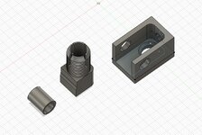
Seemed simple enough. Of course it turned into a bit of an ordeal given my lack of skills, and minimal machining experience and lack of patience and.... you get the idea. However after many broken endmills, on-the-fly design changes and a small machine crash, I do have a completed product that I'm largely pretty okay with.
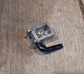
Here's the completed bracket. The bracket, lever shaft and cam lobe are 304 stainless. We drilled a hole and drove a pin (cut down drill bit) through the cam and shaft, as we did not think the press fit would hold. We unfortunately did not have any more small stainless round stock to make a lever, so I ended up cutting up an old hex key wrench, welding it to the shaft, and then painting it black. I'm not super happy with it, but I guess if I really end up hating it, I can cut it off and weld something else on later. Note the square edges in right hand side of the bracket vs the radius in the cad file. We ended breaking an endmill while radiusing the corners, and had to machine out the damage.
Here is the mirror collet post we made with the mirror installed. The two original mounts on the right show what's going on under the collet nut. We were able to get a big die to cut the threads and boring the 10mm hole was easy. The slot cutting was difficult, as we didn't have slitting saws that small, so we had to use small endmills, and it was very tedious. The radiused lip that the cam engages into was a bit of a nightmare. Long story short, we didn't look at the geometry of the cutting tool we put in the boring head close enough, and it didn't have proper clearance on the back side. It ended up putting a huge gouge into the side of the part. After grinding clearance, trying again and finshing the cam lip, I hit the other side of the collet post with the bench grinder to "balance it out" and make the gouged side look more intentional.
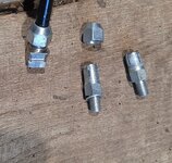
The next major hurdle is that a I made a huge error in the intial design. I intended to use an M10 flat head cap screw, so it would sit flush on the bottom of bracket. I didn't realize that 1) M10x1.25 flat head hex head cap screws are not common, and that 2) Their heads are gigantic. I ended up purchasing some M10x1.25 set screws, welding a bead on the top, and then turning a 45° taper into it. Hopefully it doesn't break. (Note: The screw I welded was much longer, I didn't build weld on top of a short screw. I just put the shorter screw next to it as an example)

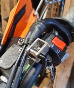
Here it is bolted on:
And here it is with the mirror installed:
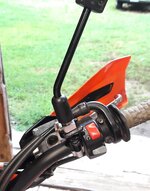
The mirror is only about 5mm higher than it originally was, and it's very solid. When the cam lever is engaged, there is absolutely no side-to-side play, and only very slight forward/backwards play (0.004"). There does not seem to be any vibrations/shaking caused by the slight forward/backwards play. If you really crank down on the lever, you can get the forward/back play to go away, but I worry about the stainless cam galling to the collet post if I do that. I did grease everything to help prevent galling.
Overall I'm pretty happy with it. It was my first pretty "technical" machining project, as most things I've done before on a milling machine were just making simple blocks or drilling hole patterns. If I had to make it again, I'd probably try design the inside of the bracket and the collet post with a slight taper, so when you engage the cam it will lock it in side/side and forward/back. ...I'd also slow down, break less endmills and make sure I have enough stock in the right material to finish the project. Ah well, it works.
The problem is you basically just smash them off everything in the woods - you have to take them off. But they're required by law, and I feel safer on the street having a mirror anyways. Taking them off is a drag because you need tools, and when you try to put them back on, they're never in the right position as the mirror is just a steel rod in a collet. The aftermarket makes chintzy small fold-up mirrors on ball joints, but they're typically small, and you still need to play around with them a bunch to get them back aligned. I was tired of dealing with that.
I decided that I would have to make something myself. The requirements are that it had to be tool-less, the mirror mounting position had to be approximately the same as stock, and it had to locate the mirror back reliably after removal. Problem 1 is I'm not an engineer, and Problem 2 is I'm not a machinist. Nevertheless, I decided to march forward with the help of a machinist friend's equipment and a bit of playing around in CAD
I came up with this basic design: A small bracket, machined out of steel will get bolted in place of the mirror's collet mount. A new collet mount will be made that accepts the original collet nut, and it will have a curved lip that a cam engages with. The cam will be a simple cylinder with a hole bored offset for a press-fit shaft to slide into.
Seemed simple enough. Of course it turned into a bit of an ordeal given my lack of skills, and minimal machining experience and lack of patience and.... you get the idea. However after many broken endmills, on-the-fly design changes and a small machine crash, I do have a completed product that I'm largely pretty okay with.
Here's the completed bracket. The bracket, lever shaft and cam lobe are 304 stainless. We drilled a hole and drove a pin (cut down drill bit) through the cam and shaft, as we did not think the press fit would hold. We unfortunately did not have any more small stainless round stock to make a lever, so I ended up cutting up an old hex key wrench, welding it to the shaft, and then painting it black. I'm not super happy with it, but I guess if I really end up hating it, I can cut it off and weld something else on later. Note the square edges in right hand side of the bracket vs the radius in the cad file. We ended breaking an endmill while radiusing the corners, and had to machine out the damage.
Here is the mirror collet post we made with the mirror installed. The two original mounts on the right show what's going on under the collet nut. We were able to get a big die to cut the threads and boring the 10mm hole was easy. The slot cutting was difficult, as we didn't have slitting saws that small, so we had to use small endmills, and it was very tedious. The radiused lip that the cam engages into was a bit of a nightmare. Long story short, we didn't look at the geometry of the cutting tool we put in the boring head close enough, and it didn't have proper clearance on the back side. It ended up putting a huge gouge into the side of the part. After grinding clearance, trying again and finshing the cam lip, I hit the other side of the collet post with the bench grinder to "balance it out" and make the gouged side look more intentional.
The next major hurdle is that a I made a huge error in the intial design. I intended to use an M10 flat head cap screw, so it would sit flush on the bottom of bracket. I didn't realize that 1) M10x1.25 flat head hex head cap screws are not common, and that 2) Their heads are gigantic. I ended up purchasing some M10x1.25 set screws, welding a bead on the top, and then turning a 45° taper into it. Hopefully it doesn't break. (Note: The screw I welded was much longer, I didn't build weld on top of a short screw. I just put the shorter screw next to it as an example)
Here it is bolted on:
And here it is with the mirror installed:
The mirror is only about 5mm higher than it originally was, and it's very solid. When the cam lever is engaged, there is absolutely no side-to-side play, and only very slight forward/backwards play (0.004"). There does not seem to be any vibrations/shaking caused by the slight forward/backwards play. If you really crank down on the lever, you can get the forward/back play to go away, but I worry about the stainless cam galling to the collet post if I do that. I did grease everything to help prevent galling.
Overall I'm pretty happy with it. It was my first pretty "technical" machining project, as most things I've done before on a milling machine were just making simple blocks or drilling hole patterns. If I had to make it again, I'd probably try design the inside of the bracket and the collet post with a slight taper, so when you engage the cam it will lock it in side/side and forward/back. ...I'd also slow down, break less endmills and make sure I have enough stock in the right material to finish the project. Ah well, it works.