Hi all,
I'm working on an old B&D/Dewalt model 3574 radial arm saw. It is a 220V, single phase. The power cord, the cable for the switch and the cable for the motor all go to a box containing the motor control. The on/off switch at the front of the machine is busted. I can't find a replacement, so I'm wiring in another switch which will be mounted at the front of the saw under the table.

Looking at the back of the broken switch, there is a black, white and green wire. I was assuming that the switch pulls 120V out of the 240V circuit to operate the motor control. If that is the case, the black and white would be the circuit that would be closed when the switch is turned on, and the green is a ground. But looking at the motor control, the green is attached directly across from the white... Is this actually a ground or is it something else?

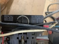
I don't have any experience with motor controls, nor does anyone I know. This saw ran for years like this, so I'm assuming it's wired correctly. In order to wire in the new switch in the picture, I was planning to hook in the black and white across from each other. This would be connected to the motor control in the same places the existing black and white are located. The ground would be connected to the ground screw in the switch.

Would this be correct?
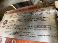
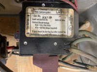
Not sure if it helps, but here's shots of the plate on the motor as well as the markings on the motor control. Thanks for the help!


I'm working on an old B&D/Dewalt model 3574 radial arm saw. It is a 220V, single phase. The power cord, the cable for the switch and the cable for the motor all go to a box containing the motor control. The on/off switch at the front of the machine is busted. I can't find a replacement, so I'm wiring in another switch which will be mounted at the front of the saw under the table.
Looking at the back of the broken switch, there is a black, white and green wire. I was assuming that the switch pulls 120V out of the 240V circuit to operate the motor control. If that is the case, the black and white would be the circuit that would be closed when the switch is turned on, and the green is a ground. But looking at the motor control, the green is attached directly across from the white... Is this actually a ground or is it something else?
I don't have any experience with motor controls, nor does anyone I know. This saw ran for years like this, so I'm assuming it's wired correctly. In order to wire in the new switch in the picture, I was planning to hook in the black and white across from each other. This would be connected to the motor control in the same places the existing black and white are located. The ground would be connected to the ground screw in the switch.
Would this be correct?
Not sure if it helps, but here's shots of the plate on the motor as well as the markings on the motor control. Thanks for the help!