shooon
Well-known member
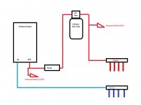
Just in the planning stages of where to mount components for my radiant heat setup. I plan to use 1" copper pipe to interconnect everything. The thermostat will fire the pump which will in turn kick the tankless heater on. Not shown- I will have isolation valves on either side of the pump for ease of serviceability.
When choosing between a boiler and tankless heater I opted to go with the tankless to keep cost down because I figured my setup is just for a single zone with 1 pump. If I had multiple zones and more than 1 pump I would have gone with the boiler to provide a better range of control.
For components I'm using:
-Grundfos 1558 Pump
-Rheem RTG-94DVLN Tankless Heater
-3 Gallon Expansion Tank (with air scrubber / coalscer)
-1" SS. 4 loop manifolds
-The 4 pex circuits are 1/2" and are in the 125 - 135 ft. range.
The attached picture is kind of how I was thinking of doing the layout. Had some questions though cause I've seen things setup differently.
Should the expansion tank (with air scrubber) be the highest point of the system? Most systems I've seen show them down low. I am thinking the air bleed should be slightly higher than the heat exchanger on the tankless unit in order to be most effective.
I will be using the factory supplied PSV with the tankless heater and will also have an additional PSV near the expansion tank. Do my component locations look ok? Any recommendations for changes?
Do I need service valves for the heater or am I probably fine with ball valves since the manifold has all the same ports as service valves would?
When choosing between a boiler and tankless heater I opted to go with the tankless to keep cost down because I figured my setup is just for a single zone with 1 pump. If I had multiple zones and more than 1 pump I would have gone with the boiler to provide a better range of control.
For components I'm using:
-Grundfos 1558 Pump
-Rheem RTG-94DVLN Tankless Heater
-3 Gallon Expansion Tank (with air scrubber / coalscer)
-1" SS. 4 loop manifolds
-The 4 pex circuits are 1/2" and are in the 125 - 135 ft. range.
The attached picture is kind of how I was thinking of doing the layout. Had some questions though cause I've seen things setup differently.
Should the expansion tank (with air scrubber) be the highest point of the system? Most systems I've seen show them down low. I am thinking the air bleed should be slightly higher than the heat exchanger on the tankless unit in order to be most effective.
I will be using the factory supplied PSV with the tankless heater and will also have an additional PSV near the expansion tank. Do my component locations look ok? Any recommendations for changes?
Do I need service valves for the heater or am I probably fine with ball valves since the manifold has all the same ports as service valves would?