To avoid these ads, REGISTER NOW!

reading a micrometer?

sierra3dr

Member
Joined
May 29, 2014
Messages
8
OK ladies and gents,I hope you all are ok.
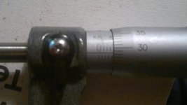
I'm in the process in building an engine which I have done several times,and I've never had issues with standard shells. On this build,the crank doesn't turn once torqued up. I've concluded that the standard shells are thicker and plastigauge doesn't help,as it reads that there's and gap on the journals. I've decided to purchase a dial bore gauge and a micrometer set. I'd be grateful if someone could let me know if I'm reading the following readings correctly? Left picture 54.543mm,right picture 54.528mm.
Thankyou
 

Attachments

  • 2016-11-18-2400.jpg
    2016-11-18-2400.jpg
    34.2 KB · Views: 347
  • 2016-11-18-2403.jpg
    2016-11-18-2403.jpg
    29.8 KB · Views: 264
To avoid these ads, REGISTER NOW!

rlitman

Well-known member
Joined
Oct 18, 2010
Messages
24,576
Location
Long Island
No. Each turn of the thimble represents 1/2 mm, not 1mm. That's why it counts up to 50.
The lines on top of the barrel represent the whole mm's, and the offset lines on the bottom represent the halves.

In the first picture, you've got to add your 0.43mm from the thimble to 54.5mm on the barrel, NOT 54.0mm. So I see 54.93mm. My metric micrometer that reads to 1/1000mm does that with a vernier scale on the barrel (it also divides mm into quarters and not halves, so the thimble only counts to 25).
 
Last edited:

rlitman

Well-known member
Joined
Oct 18, 2010
Messages
24,576
Location
Long Island
Don't take my word for it, wait for someone with more experience. But I would have said 55.435 and 55.285.

Your .005 is a good point. It does appear to be not exactly on the line. But not having the micrometer in my hand where I can look at it straight on, I won't guess what the parallax error is.
 
OP
S

sierra3dr

Member
Joined
May 29, 2014
Messages
8
No. Each turn of the thimble represents 1/2 mm, not 1mm. That's why it counts up to 50.
The lines on top of the barrel represent the whole mm's, and the offset lines on the bottom represent the halves.
aha...I had it partially correct

In the first picture, you've got to add your 0.43mm from the thimble to 54.5mm on the barrel, NOT 54.0mm. So I see 54.93mm.
oh right,so that's where I was going wrong :thumbup: thanks ever so much ritman.
And Mike,thanks for your input:thumbup:
 

MBfreak

MEMBER EMERITUS
Joined
Dec 10, 2010
Messages
2,301
Location
Linkoping , Sweden
Reading a micrometer, metric style, down to fractions of 1/100 mm is of course possible. But not necessarily very accurate. To read 1/1000 of a mm on a crank journal you need other stuff, so expensive that no hobby shop is likely to invest in it. If you are a machinist, buy it by all means.
But for micrometer readings to be meaningful you will need very controlled method as to torque on the spinner and placing it on the journal.
Temperature differential between micrometer and journal will also have an impact.

If the crank "sticks" even though the journals and bearings are correct the crank or bearing seats in the block are out of true. It can also be a deformed cap, they go "eggy" quite easy if the engine has been knocking.


Best regards

Ola
 

larry_g

Well-known member
Joined
Apr 28, 2007
Messages
16,858
Location
oregon
What engine are you working on?
Are these the main bearings, if so how many?
What prep work has been done?
Line bore the mains?
Turn the crank mains and rods?
Did you check if the crank is straight?

Any catastrophic failure lead to this rebuild?

lg
no neat sig line
 

pstemari

Well-known member
Joined
Jan 7, 2012
Messages
903
Location
Seattle
Something's a bit wonky with that mic. If the barrel is at 0.43, the edge should be just left of a line. However, it looks to be just *right* of the 55.0 line. Past 55.0 and before 55.5 would give a reading of 55.43.

Sent from my Nexus 6 using Tapatalk
 

TigerDude

Well-known member
Joined
Feb 24, 2016
Messages
127
Location
Atlanta, GA USA
No. Each turn of the thimble represents 1/2 mm, not 1mm. That's why it counts up to 50.
The lines on top of the barrel represent the whole mm's, and the offset lines on the bottom represent the halves.

In the first picture, you've got to add your 0.43mm from the thimble to 54.5mm on the barrel, NOT 54.0mm. So I see 54.93mm. My metric micrometer that reads to 1/1000mm does that with a vernier scale on the barrel (it also divides mm into quarters and not halves, so the thimble only counts to 25).
This is correct.

Are you also using the friction knob to close the mic? It should adjust to zero with the friction knob when closed all the way.
 

pstemari

Well-known member
Joined
Jan 7, 2012
Messages
903
Location
Seattle
Judging from the photo it's a 50-75mm mic, so you'd need a calibration standard to set the zero position.

Sent from my Nexus 6 using Tapatalk
 
To avoid these ads, REGISTER NOW!

Gert

Well-known member
Joined
Feb 21, 2012
Messages
139
Location
Netherlands
You could check/verify your reading by using another measuring device, for example a (digital) caliper.
 

catalytic

Well-known member
Joined
Jul 16, 2011
Messages
636
Location
Boston, Los Angeles, Cleveland
No. Each turn of the thimble represents 1/2 mm, not 1mm. That's why it counts up to 50.
The lines on top of the barrel represent the whole mm's, and the offset lines on the bottom represent the halves.

In the first picture, you've got to add your 0.43mm from the thimble to 54.5mm on the barrel, NOT 54.0mm. So I see 54.93mm. My metric micrometer that reads to 1/1000mm does that with a vernier scale on the barrel (it also divides mm into quarters and not halves, so the thimble only counts to 25).

^^ this is correct. It takes a second to switch your thinking if you're used to reading imperial (inch) mic's... the 1/2mm graduations on the barrel throw people for a loop all the time.
 

Advan

Well-known member
Joined
May 25, 2014
Messages
442
Location
Ontario, Canada
55.43 and 54.78mm. However, something seems wrong in the first pic. We shouldn't be able to see that much of the 55mm barrel line.....
 

rlitman

Well-known member
Joined
Oct 18, 2010
Messages
24,576
Location
Long Island
55.43 and 54.78mm. However, something seems wrong in the first pic. We shouldn't be able to see that much of the 55mm barrel line.....


Nah. By the time 49 rolls over to 0, the line should already be fully exposed. This looks fine to me.

MBfreak brought up temperature though. I really don't like hand held micrometers (I use mine with a micrometer vise). When you hold the frame, your hand warms it up, and now you're off zero.
 

Showkey

"MEMBER EMERITUS"
Joined
Aug 9, 2014
Messages
8,638
Location
Wausau WI
:thumbup:^^^^^^^agree:thumbup:.........scary the number of guys that can't read a metric mic and then try to convince others they can :lol_hitti:lol_hitti


The solution for the non metric mic readers, the modern ones have gone electronic digital.

mit3203036p.jpg
 
Last edited:

Advan

Well-known member
Joined
May 25, 2014
Messages
442
Location
Ontario, Canada
Nah. By the time 49 rolls over to 0, the line should already be fully exposed. This looks fine to me.

MBfreak brought up temperature though. I really don't like hand held micrometers (I use mine with a micrometer vise). When you hold the frame, your hand warms it up, and now you're off zero.


Perhaps I didn't word things correctly. My initial thought was 55.43mm, because if the reading was 54.93, I think we're seeing too much of the 55mm barrel line. Could have a lot to do with the camera angle I'm betting.
 

justanengineer

Well-known member
Joined
Apr 5, 2011
Messages
7,722
Location
Motor City
Something's a bit wonky with that mic. If the barrel is at 0.43, the edge should be just left of a line. However, it looks to be just *right* of the 55.0 line. Past 55.0 and before 55.5 would give a reading of 55.43.

Agreed. There's daylight between the thimble edge and the line, typically the thimble edge is only covering half the line width when zeroed.

Regardless, I believe the OP's falling into the common engine assembly trap of trying to measure too much. Plastigage for example hasnt been used in industry for decades due to its inaccuracy, but realistically there's no reason to use it. On a job like this the crank and block either need grinding or dont. If there's no obvious damage, use stock size bearings. If they do, have the machine shop grind them to standard sizes and tell you what size bearings to order. Simple. Not to knock anybody, but there is quite a bit of knowledge and skill involved in accurately measuring tight tolerance parts, even more so with engine parts.
 

rlitman

Well-known member
Joined
Oct 18, 2010
Messages
24,576
Location
Long Island
These metric mics do NOT read to thousandths.

I wouldn't say that at all.

In the scientific laboratory I was trained in, I learned how it is proper to read an instrument by estimating one significant figure past the finest division of the instrument. A vernier scale allows that significant figure to be taken with a much higher degree of confidence than a straight out estimate, but that doesn't mean you cannot read past the finest division. This is NOT a digital device, so there is no reason to treat it as such.

Of course, parallax must be taken into account for this to work well, and a quality instrument should minimize parallax as much as possible to help with this. In the case of a micrometer, that is done through the tapering barrel scale, and positioning your head directly above the line. It can get a little difficult on a mercury thermometer. Anything that reads a needle against a scale would be helped by a mirrored scale (short arm balance, spectrophotometer, galvanometer, etc). The reflection can be used to guarantee that you are looking straight down on the scale, when only one needle is seen against the mirror (you need one eye closed for all of this).
 
To avoid these ads, REGISTER NOW!
Top Bottom