This thread scares me. Asking such a basic question and then saying your going to frabricate a bell housing I have to ask do you understand the alignments and concentricities that you must maintain to have a working setup? Do you have the machines capable of machineing in the details necessary to do this. Or am I reading your post wrong and you have a bellhousing coming on the bus and will be modifying that?
Good luck with this adventure and keep us posted on the progress.
lg
no neat sig line
Ill hold my hands up, it is a basic question! I haven't dealt with this bush much in my past, the only time have been when changing clutches and gearboxes "like for like". In these cases I check that the clearences are sensible and that everything fits.
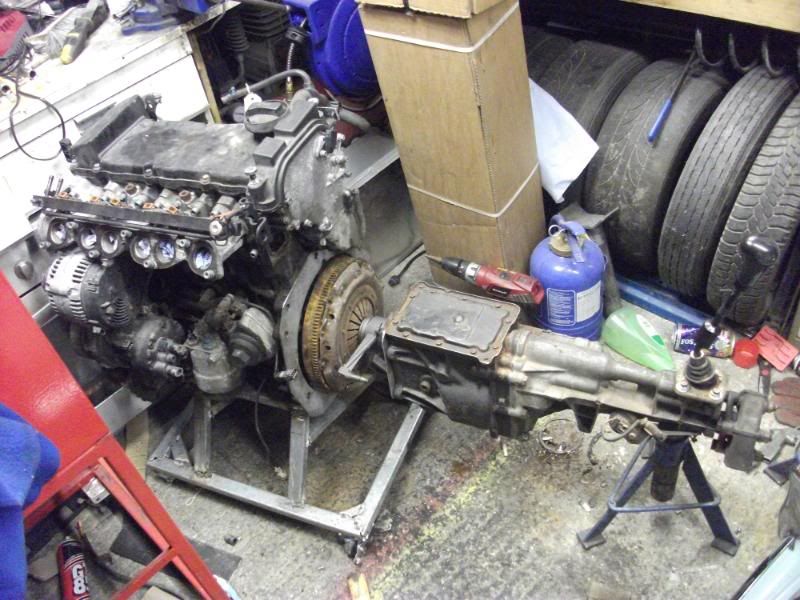
This is the first time im putting an engine and box together that were not designed for it!
I do understand the intracasies involved, tolerences and concentricness required, and unfortunately I dont have the machines I wish I had.
Thing is though that if I cant afford to get someone else to do the work and I cant afford the machines to do the work my self. I want to build this car so unfortunatly this is my only option and im going to do everything I can to make it a reality.
Aside from the ins and outs of the pilot bush im pretty clued up honest

With the release bearing clearences its the same story im afraid, ive only ever worked on standard setups where you can not see the bearing till the box is off

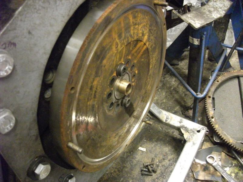
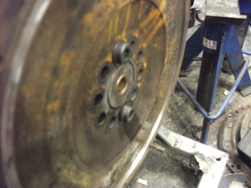
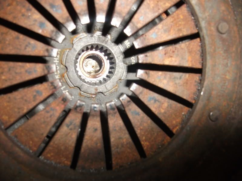
I assume you found a bushing for that and not a bearing. You don't want to use a taper bearing because there's no way to provide the necessary pre-load. You could use a needle bearing if the input shaft is hardened for that purpose(ie. if the original application used them).
I did manage to find a bushing in the end
so no preload etc to worry about
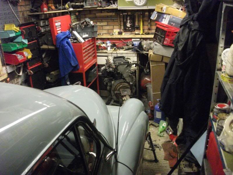
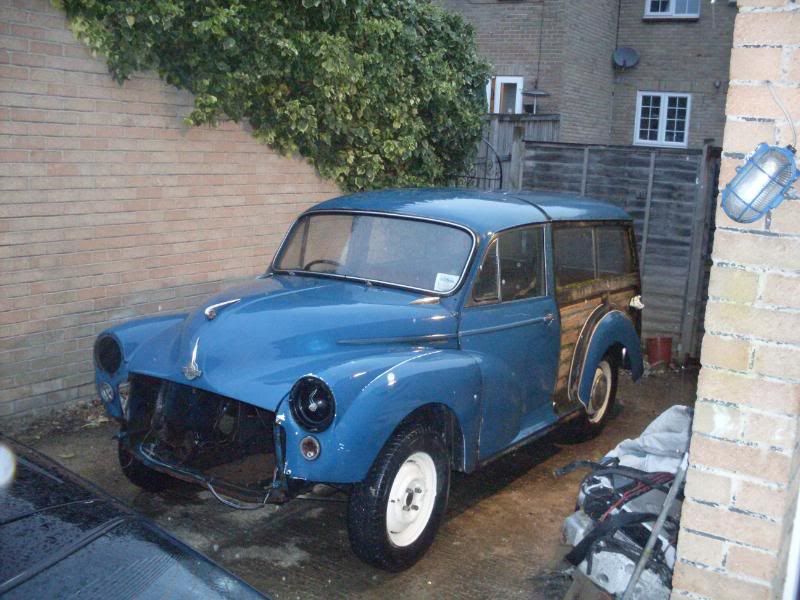
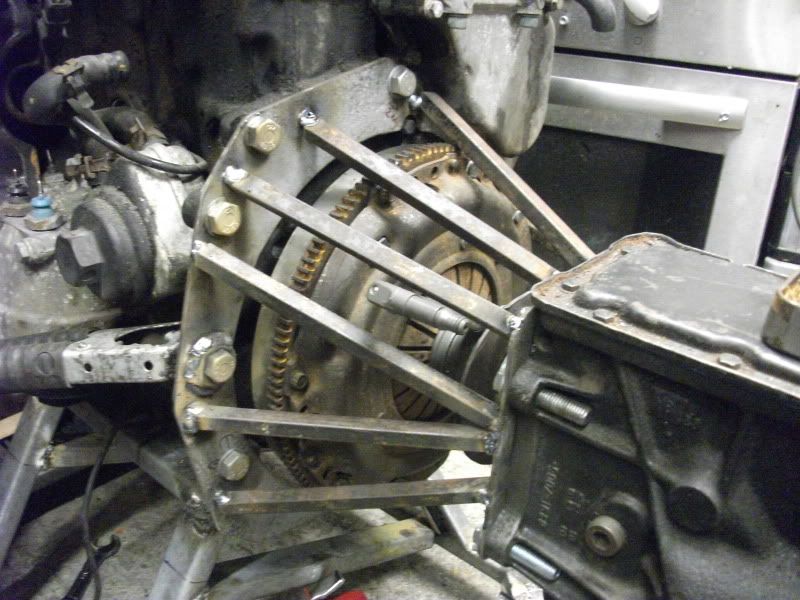
I'm guessing that not more than a mm would be good clearance. You don't want the throw out bearing to drag and you don't want wasted motion either. What is this power train going into? Is that an old Morris Minor? What is the engine?
<1mm, OK. good job I checked as I was considering starting at 5mm and shimming 1mm at a time to ensure correct operation.
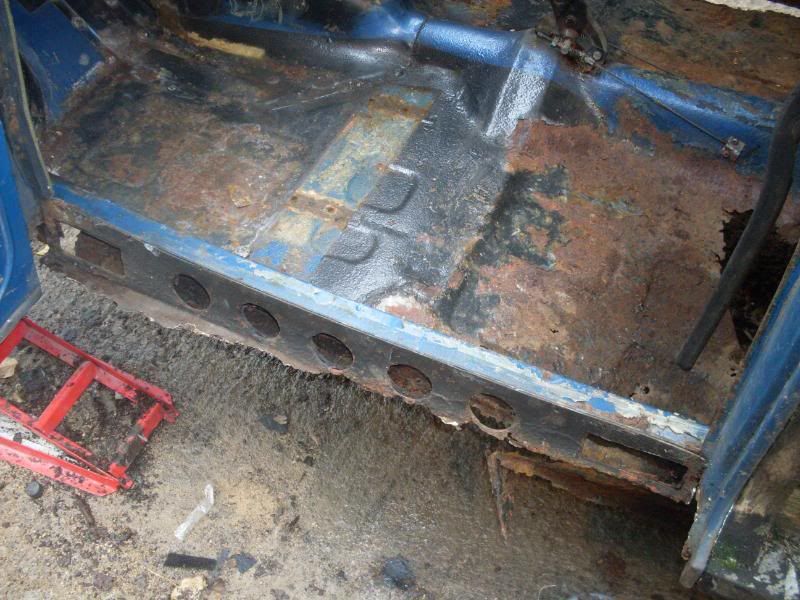
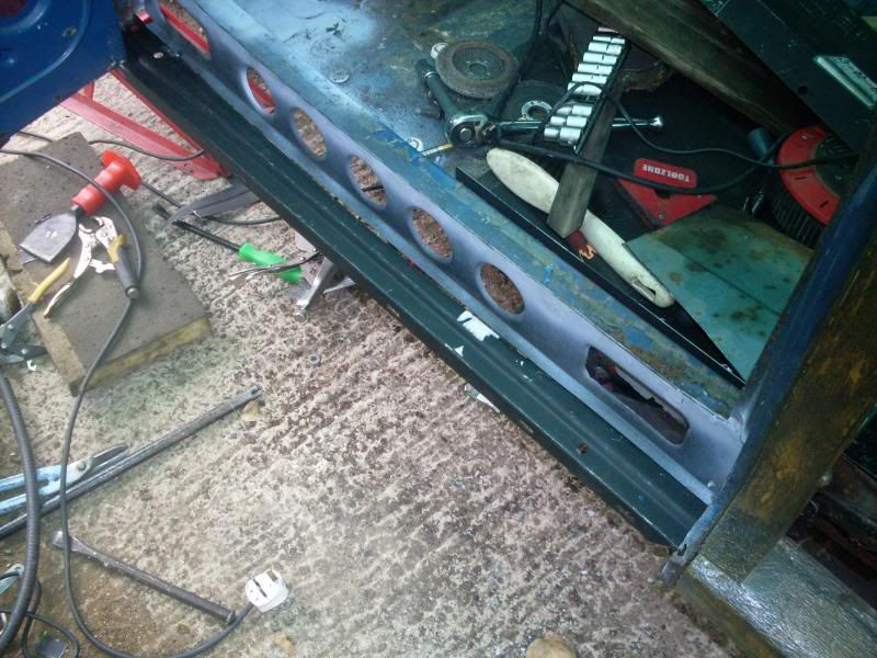
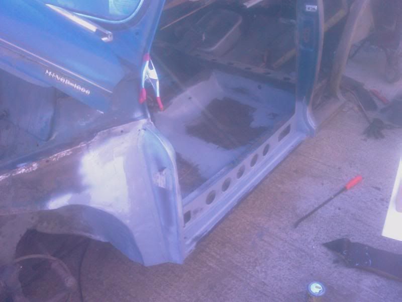
As for the car, it is indeed the old morris minor! and a rather grotty example at that!
I have been a busy camper too!
I've just read what I've written above and some of it comes across as "defensive", NOT intentional! hopefully I've cleared up any confusion.
I'm learning as I go in some respects on this one (and as far as I know it will be the first front engine RWD VR6 that's been done) so your help is appreciated.