To avoid these ads, REGISTER NOW!

Rebel Pioneer Mini Split Install

jonathan75

Well-known member
Joined
Mar 27, 2013
Messages
1,451
Location
NC
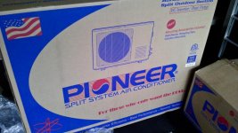
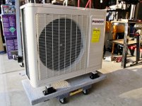
I will call this a Rebel install because I am using a brand that does not seem too popular yet. It is much cheaper then the mainstream Japanese brands which could give one pause due to the low price, but based on my research I think it is worth the risk. Here are some positives and FAQ's that I have learned so far.

There is a company in Florida called Parker Davis HVAC International, Inc. They have these Mini Splits made for them. In the US Distribution they are called Pioneer but overseas they have different names. Sorry but I do not recall the list of names they told me over the phone. But the Pioneer Mini Split has nothing to do with with the electronics company or Pepsi Cola.

They stand by their products and fully stock all the parts here in the US at their Florida Warehouse.

Parker Davis (HighSeer.com) does not punish you for being a homeowner (DIY) or not being a professional installer. The warranty is still valid and they back their product 100% for the warranty period and after that you can purchase parts needed at reasonable prices. If you do have a issue they will help you figure out the problem via phone support and ship you the part right away. You can even download the service manual for no charge.

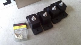
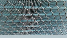
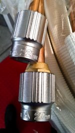
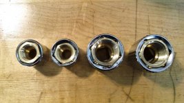
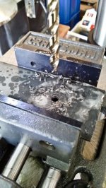
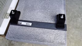
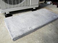
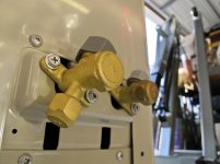
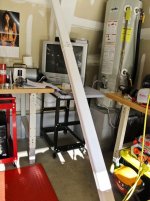
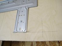
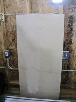
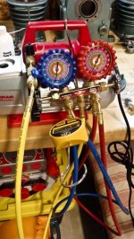
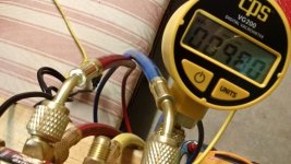
Anyway, talk is cheap. Here are some pictures! The unit arrived today, thus the start of the thread.

http://www.highseer.com/

attachment.php
 

Attachments

  • DSC_4023-1.jpg
    DSC_4023-1.jpg
    66.8 KB · Views: 3,971
To avoid these ads, REGISTER NOW!
OP
J

jonathan75

Well-known member
Joined
Mar 27, 2013
Messages
1,451
Location
NC
Picture 1 = Just some parts I got.
Picture 2 = More parts, HVAC supply houses are great.
Picture 3 = Just your friendly neighborhood R&L truck driver.
Picture 4 = That was the only damage I found.
Picture 5 = Nice little slab I picked up today. Should fit perfect. For $15 dollars you can't beat it.
Picture 6 = Rubber isolation mounts. Paid $15 for those too.
Picture 7 = The unit still in the box.
 

Attachments

  • DSC_4030-1.jpg
    DSC_4030-1.jpg
    77.6 KB · Views: 460
  • DSC_4028-1.jpg
    DSC_4028-1.jpg
    55.6 KB · Views: 471
  • DSC_4026-1.jpg
    DSC_4026-1.jpg
    46.2 KB · Views: 552
  • DSC_4024-1.jpg
    DSC_4024-1.jpg
    151.8 KB · Views: 520
  • DSC_4023-1.jpg
    DSC_4023-1.jpg
    66.8 KB · Views: 405
  • DSC_4021-1.jpg
    DSC_4021-1.jpg
    84 KB · Views: 517
  • DSC_4018-1.jpg
    DSC_4018-1.jpg
    41.8 KB · Views: 524
OP
J

jonathan75

Well-known member
Joined
Mar 27, 2013
Messages
1,451
Location
NC
Picture 1 and 2 = Where are my Vibration Absorbers mentioned on the box? Seems they tear open the bag and take them out. The bag had a hole in it. Guess they figure you don't need it if you purchase the upgrade ones. Really wish they would give you everything. I still need to get their side of the story but that is what it looks like.

Picture 3 = The fit and finish is great. Looks very high quality except for the plastic grill that wraps around the fins in the back side. It is kind of loose and sloppy.

Picture 4 = That is High Seer!

Picture 5 = Interesting, Japanese Design and Made in China. Guess that means Japanese clone. But you know many of the models they offer do have Panasonic motors in them. My 18,0000 model did not though.

Picture 6 = Parts bag.
 

Attachments

  • DSC_4046-1.jpg
    DSC_4046-1.jpg
    79.5 KB · Views: 344
  • DSC_4042-1.jpg
    DSC_4042-1.jpg
    76.9 KB · Views: 342
  • DSC_4038-1.jpg
    DSC_4038-1.jpg
    47 KB · Views: 490
  • DSC_4037-1.jpg
    DSC_4037-1.jpg
    105 KB · Views: 345
  • DSC_4031-1.jpg
    DSC_4031-1.jpg
    39.9 KB · Views: 306
  • DSC_4033-1.jpg
    DSC_4033-1.jpg
    62.6 KB · Views: 290
OP
J

jonathan75

Well-known member
Joined
Mar 27, 2013
Messages
1,451
Location
NC
Here is where it went a little south. I don't like their flare nuts. And I didn't like the fact that they could not tell me correctly the size over the phone. I needed to order Flare Nut Crows Feet ahead of the shipment so I would be ready to go. But they gave me the wrong size over the phone. They told me it would be 1 1/8 for the 5/8 line but it is really 1 1/16. Actually it is Metric or SAE. Just everything you find for the 3/8 line is sloppy. The size of the 3/8 flare nut is very off and nothing will fit snug on it. The 5/8 line is better. Now compared to the flare nuts I picked up at my local HVAC supply house the local nuts are much better and will fit snug in Metric or SAE.

Pioneer Line Kit Flare Nuts
3/8 Line = 22mm or 7/8" (Sloppy fit, 22mm slightly better fit over 7/8")
5/8 Line = 27mm or 1 1/16" (Okay fit but not perfect)

HVAC Supply House Flare Nuts
3/8 Line = 21mm or 13/16" (Very snug and perfect fit)
5/8 Line = 27mm or 1 1/16" (Very snug and perfect fit)
 

Attachments

  • DSC_4063-1.jpg
    DSC_4063-1.jpg
    41 KB · Views: 324
  • DSC_4061-1.jpg
    DSC_4061-1.jpg
    47.1 KB · Views: 351
  • DSC_4058-1.jpg
    DSC_4058-1.jpg
    73.4 KB · Views: 293
  • DSC_4057-1.jpg
    DSC_4057-1.jpg
    68.6 KB · Views: 315
  • DSC_4055-1.jpg
    DSC_4055-1.jpg
    83.2 KB · Views: 358
  • DSC_4054-1.jpg
    DSC_4054-1.jpg
    38.8 KB · Views: 336
  • DSC_4052-1.jpg
    DSC_4052-1.jpg
    42.8 KB · Views: 365
Last edited:
OP
J

jonathan75

Well-known member
Joined
Mar 27, 2013
Messages
1,451
Location
NC
Here is what came with the unit. Except the adapter you have to purchase separate. I have no idea what those small extension lines are for.

Update: Those extension lines are adapters to hook to my line set. I wish it would connect directly! Now I have four more points of failure and leak. Great!
 

Attachments

  • DSC_4067-1.jpg
    DSC_4067-1.jpg
    57.2 KB · Views: 451
  • DSC_4069-1.jpg
    DSC_4069-1.jpg
    86.9 KB · Views: 350
Last edited:

sparelman

Member
Joined
Aug 23, 2012
Messages
9
Location
Virginia
Will you be doing the install over this weekend? I am interested in hearing your impressions on this product - in terms of performance.
 
OP
J

jonathan75

Well-known member
Joined
Mar 27, 2013
Messages
1,451
Location
NC
Will you be doing the install over this weekend? I am interested in hearing your impressions on this product - in terms of performance.

I hope to finish this weekend but I am running behind already. And only have half a day Saturday to finish up what I don't do today.
 
OP
J

jonathan75

Well-known member
Joined
Mar 27, 2013
Messages
1,451
Location
NC
Can someone help describe to me better how to do the vacuum part? The manual has me scratching my head a little. I would like to understand the theory behind it and how the valves operate. But right now I don't understand how to do this in the right steps. Please see attached manual pictures.

I picked up a manifold today and will use a neighbors vacuum pump. I don't plan on using a micron gauge.

attachment.php


attachment.php
 

Attachments

  • Pioneer 2.jpg
    Pioneer 2.jpg
    136.2 KB · Views: 3,841
  • Pioneer 0.jpg
    Pioneer 0.jpg
    92.2 KB · Views: 3,850

cspcrx

Well-known member
Joined
May 2, 2014
Messages
608
Location
Phoenix, AZ
Yes no help but eager to hear how it goes. I want to do a mini split in my 4 car, 24,000BTU, myself. Will watch for updates.
 

jad3675

Well-known member
Joined
Jul 12, 2010
Messages
52
Can someone help describe to me better how to do the vacuum part? The manual has me scratching my head a little. I would like to understand the theory behind it and how the valves operate. But right now I don't understand how to do this in the right steps. Please see attached manual pictures.

I picked up a manifold today and will use a neighbors vacuum pump. I don't plan on using a micron gauge.

First, you really should use a micron gauge. The manifold is not anywhere near accurate enough.

As for the process. The vac pump connects to the center port on the manifold set. Connect the low pressure hose (blue) to the schraeder valve on the outdoor unit. Open the low pressure valve 100% and run the vac pump until sufficent vacuum is achieved. Close of the valve on the manifold, so that vac only exists in the low pressure side of the manifold. When they ask you to crack the valve, they want a little bit of pressure in the system so that when you disconnect the manifold you don't draw are into the system - instead, you'll expel a bit of R410a. Once you're disconnected from the schraeder valve and the cap is torqued, you'll be able to fully release the charge. You'll need to duplicate this step for each head unit.

John
 
OP
J

jonathan75

Well-known member
Joined
Mar 27, 2013
Messages
1,451
Location
NC
First, you really should use a micron gauge. The manifold is not anywhere near accurate enough.

As for the process. The vac pump connects to the center port on the manifold set. Connect the low pressure hose (blue) to the schraeder valve on the outdoor unit. Open the low pressure valve 100% and run the vac pump until sufficent vacuum is achieved. Close of the valve on the manifold, so that vac only exists in the low pressure side of the manifold. When they ask you to crack the valve, they want a little bit of pressure in the system so that when you disconnect the manifold you don't draw are into the system - instead, you'll expel a bit of R410a. Once you're disconnected from the schraeder valve and the cap is torqued, you'll be able to fully release the charge. You'll need to duplicate this step for each head unit.

John

Thank you John, you explained it very well! After trying all day I finally got tech support before they closed. The only thing different they said is to open the liquid side for 3 seconds or so after doing the vacuum and close it back up again. That way I can check for leaks using bubble solution and not have to risk your whole charge if there is a problem. If everything checks out okay they said to open both liquid and gas side all the way. They also told me to keep the manifold attached so I can monitor the pressure and to disconnect it after I saw it run in heat and in cool. Hopefully I understood correctly. Does anyone disagree with what they told me to do?
 
OP
J

jonathan75

Well-known member
Joined
Mar 27, 2013
Messages
1,451
Location
NC
Here are some progress pictures of today. Besides running around all morning for more parts I did get the base done and tested and set up the vacuum pump and gauges.

The problem with the fake slab I got is that it is mostly foam with some kind of hard shell on the outside. I thought I should reinforce under the slab since there is really nothing but foam to bolt to. The pictures will explain the rest.
 

Attachments

  • DSC_4091-1.jpg
    DSC_4091-1.jpg
    62.1 KB · Views: 401
  • DSC_4090-1.jpg
    DSC_4090-1.jpg
    96.7 KB · Views: 420
  • DSC_4089-1.jpg
    DSC_4089-1.jpg
    87.3 KB · Views: 374
  • DSC_4087-1.jpg
    DSC_4087-1.jpg
    81.1 KB · Views: 389
  • DSC_4083-1.jpg
    DSC_4083-1.jpg
    101.1 KB · Views: 363
  • DSC_4082-1.jpg
    DSC_4082-1.jpg
    95.7 KB · Views: 400
  • DSC_4081-1.jpg
    DSC_4081-1.jpg
    84.9 KB · Views: 418
Last edited:
OP
J

jonathan75

Well-known member
Joined
Mar 27, 2013
Messages
1,451
Location
NC
I painted the metal to hopefully keep it from rusting too fast. It will have direct ground contact but I will compact some small rocks at the base to help with water runoff.

I painted with Rustoleum Black Hammered Finish.
 

Attachments

  • IMG_4084-1.jpg
    IMG_4084-1.jpg
    116.2 KB · Views: 279
  • IMG_4079-1.jpg
    IMG_4079-1.jpg
    134.3 KB · Views: 361
  • IMG_4077-1.jpg
    IMG_4077-1.jpg
    108.3 KB · Views: 243
  • IMG_4070-1.jpg
    IMG_4070-1.jpg
    150.8 KB · Views: 215
  • IMG_4067-1.jpg
    IMG_4067-1.jpg
    157.2 KB · Views: 214
  • IMG_4064-1.jpg
    IMG_4064-1.jpg
    121.2 KB · Views: 228
  • IMG_4063-1.jpg
    IMG_4063-1.jpg
    139.1 KB · Views: 255
OP
J

jonathan75

Well-known member
Joined
Mar 27, 2013
Messages
1,451
Location
NC
Here you can see the manifold gauge I picked up today. It was only $47. Should be good enough for what I need to do. I really would like a Micron gauge but they are really expensive. So I will just try to see if the pressure rises after I turn off the pump and check for leaks when I apply pressure to the system.

The pump my neighbor is letting me use was brand new in the box. I even had to put oil in it.

The big gutter will be used to hide the lines on the outside.
 

Attachments

  • IMG_4086-1.jpg
    IMG_4086-1.jpg
    62.7 KB · Views: 361
  • IMG_4074-1.jpg
    IMG_4074-1.jpg
    66.5 KB · Views: 382
  • IMG_4073-1.jpg
    IMG_4073-1.jpg
    99.2 KB · Views: 438
  • IMG_4071-1.jpg
    IMG_4071-1.jpg
    113.8 KB · Views: 386

jad3675

Well-known member
Joined
Jul 12, 2010
Messages
52
Here you can see the manifold gauge I picked up today. It was only $47. Should be good enough for what I need to do. I really would like a Micron gauge but they are really expensive. So I will just try to see if the pressure rises after I turn off the pump and check for leaks when I apply pressure to the system.

The pump my neighbor is letting me use was brand new in the box. I even had to put oil in it.

The big gutter will be used to hide the lines on the outside.

You can get an inexpensive micron gauge for under $90.
http://www.testequipmentdepot.com/products.htm?item=AVG2&ref=gbase&gclid=CNfN1Mn8sr4CFRAaOgodvS0AvQ

The coupon code off5perc knock off 5% from your order.

Sell it on CL when you're done for what you paid for it.

Nice vac pump, too. That should be able to draw down the system pretty quickly. If you're doing more than one indoor unit and need to vacuum more than one lineset, change the oil between runs. You can buy a 64oz jug from Advance Auto for about $8.

Does your manifold have low loss fittings or ball valves on the end?

John
 
OP
J

jonathan75

Well-known member
Joined
Mar 27, 2013
Messages
1,451
Location
NC
You can get an inexpensive micron gauge for under $90.
http://www.testequipmentdepot.com/products.htm?item=AVG2&ref=gbase&gclid=CNfN1Mn8sr4CFRAaOgodvS0AvQ

The coupon code off5perc knock off 5% from your order.

Sell it on CL when you're done for what you paid for it.

Nice vac pump, too. That should be able to draw down the system pretty quickly. If you're doing more than one indoor unit and need to vacuum more than one lineset, change the oil between runs. You can buy a 64oz jug from Advance Auto for about $8.

Does your manifold have low loss fittings or ball valves on the end?

John

So the micron pump you gave the link for, at what level does it trigger the green light?

Why do you need to change the oil between runs?

How do I tell if I have low loss fitting or ball valves?
 
OP
J

jonathan75

Well-known member
Joined
Mar 27, 2013
Messages
1,451
Location
NC
I didn't have much time to work on this today. Only until 2pm. And tomorrow I have to leave town again. So I didn't get to finish everything. I will need to wait until I get back to finish.

I used Birch Plywood panels for the walls. Actually I plan to insulate and use plywood for all the walls after I add insulation. I will add another 2x4 where the panels meet later but didn't have time to do that today.

Everything in the manual is metric so I had to convert for my rulers.
 

Attachments

  • IMG_4104-1.jpg
    IMG_4104-1.jpg
    63.7 KB · Views: 278
  • IMG_4098-1.jpg
    IMG_4098-1.jpg
    81.6 KB · Views: 342
  • IMG_4097-1.jpg
    IMG_4097-1.jpg
    91.9 KB · Views: 299
  • IMG_4095-1.jpg
    IMG_4095-1.jpg
    49.4 KB · Views: 315
  • IMG_4093-1.jpg
    IMG_4093-1.jpg
    92.3 KB · Views: 270
  • IMG_4088-1.jpg
    IMG_4088-1.jpg
    123.5 KB · Views: 271
  • IMG_4087-1.jpg
    IMG_4087-1.jpg
    46.5 KB · Views: 277
OP
J

jonathan75

Well-known member
Joined
Mar 27, 2013
Messages
1,451
Location
NC
I drilled a guide hole at the correct angle down at the exact position the manual told me to. First I drilled the inside hole, then just the vinyl siding and then the final hole was angled up from the outside.
 

Attachments

  • IMG_4122-1.jpg
    IMG_4122-1.jpg
    86.2 KB · Views: 206
  • IMG_4119-1.jpg
    IMG_4119-1.jpg
    131.3 KB · Views: 200
  • IMG_4117-1.jpg
    IMG_4117-1.jpg
    53.4 KB · Views: 201
  • IMG_4115-1.jpg
    IMG_4115-1.jpg
    97.7 KB · Views: 192
  • IMG_4110-1.jpg
    IMG_4110-1.jpg
    101.3 KB · Views: 196
  • IMG_4108-1.jpg
    IMG_4108-1.jpg
    104.7 KB · Views: 200
  • IMG_4106-1.jpg
    IMG_4106-1.jpg
    68.8 KB · Views: 204
Last edited:
OP
J

jonathan75

Well-known member
Joined
Mar 27, 2013
Messages
1,451
Location
NC
Included with the kit was a tube to run in the wall. I used silicone caulk where the face attaches and then ran a lot of silicone where it meets the wall. I kept it all in with a few screws since it is at a angle. The screws are not straight but it will be covered up with gutter later. After that I just trimmed the excess off so it would not interfere with the inside unit sitting flush.
 

Attachments

  • IMG_4149-1.jpg
    IMG_4149-1.jpg
    95 KB · Views: 320
  • IMG_4148-1.jpg
    IMG_4148-1.jpg
    60.4 KB · Views: 257
  • IMG_4143-1.jpg
    IMG_4143-1.jpg
    64.1 KB · Views: 272
  • IMG_4140-1.jpg
    IMG_4140-1.jpg
    83.8 KB · Views: 222
  • IMG_4126-1.jpg
    IMG_4126-1.jpg
    85.4 KB · Views: 235
  • IMG_4124-1.jpg
    IMG_4124-1.jpg
    35.1 KB · Views: 225
To avoid these ads, REGISTER NOW!
OP
J

jonathan75

Well-known member
Joined
Mar 27, 2013
Messages
1,451
Location
NC
I wrapped the pipes together with the electrical line. The manual does not talk about putting the electrical line with it but I could not imagine having to fish that back in later.

I need to leave town so in the morning I would like to bend the pipe down and wrap up the cord before I leave. What is the best way to bend the pipe without putting a kink in it?
 

Attachments

  • IMG_4160-1.jpg
    IMG_4160-1.jpg
    115.2 KB · Views: 350
  • IMG_4158-1.jpg
    IMG_4158-1.jpg
    54.2 KB · Views: 304
  • IMG_4156-1.jpg
    IMG_4156-1.jpg
    76.6 KB · Views: 294
  • IMG_4154-1.jpg
    IMG_4154-1.jpg
    73.1 KB · Views: 302
  • IMG_4152-1.jpg
    IMG_4152-1.jpg
    91 KB · Views: 328

smokey0810

Well-known member
Joined
Mar 29, 2013
Messages
3,056
Location
Canyon, Texas
Installed one of these units a few months back. 9K BTU Heat/Air pump in our master bedroom. Really easy install. Run all the wires through the hole, just like you have in the photo. I would slowly bend the copper tubing in the direction you want it to go towards your condenser unit. Thats what I did, making sure the plastic tubing for condensation was facing downwards. I mounted my outside unit to two 18" x 18" concrete pavers.
Only part I had to purchase was the adapter to use with the gauges.
I made the stupid mistake of running the unit without having it vacuumed out first, and burnt out the compressor. Pioneer sent me a new compressor, free of charge, and had a friend of mine install it that used to do HVAC work. 1 hr later, it was up and running.
I would call around to friends and see who can evac the system properly for you, if you have no experience. I called some local HVAC places, and they quoted from $200 to $500 to do it. My buddy did everything for $150.
 

smokey0810

Well-known member
Joined
Mar 29, 2013
Messages
3,056
Location
Canyon, Texas
Once I had the lines wrapped together with the vinyl tape, I mounted them to my outside wall with clamps for mounting conduit to walls. Spray painted the lines brown to blend in with the house. Unit truly kicks **** for the price.
Also realize that each unit is charged for a certain line set distance, so the farther u run your lines, the more freon u will need. I think my unit was 2.9 lbs of freon for a distance of up to 15 ft. I just mounted my condenser at the end of the lines so I would not have to cut and flare them.
 
OP
J

jonathan75

Well-known member
Joined
Mar 27, 2013
Messages
1,451
Location
NC
I made the stupid mistake of running the unit without having it vacuumed out first, and burnt out the compressor. Pioneer sent me a new compressor, free of charge, and had a friend of mine install it that used to do HVAC work. 1 hr later, it was up and running.
I would call around to friends and see who can evac the system properly for you, if you have no experience. I called some local HVAC places, and they quoted from $200 to $500 to do it. My buddy did everything for $150.

I didn't know it would be an immediate effect to burn out the compressor. I thought it would run for years and just fail early? Wonder if yours did have a problem anyway?

Did you watch your friend install the new compressor? How is the compressor attached? Are the lines brazed or are there flare connections inside the unit?

Also realize that each unit is charged for a certain line set distance, so the farther u run your lines, the more freon u will need. I think my unit was 2.9 lbs of freon for a distance of up to 15 ft. I just mounted my condenser at the end of the lines so I would not have to cut and flare them.

I asked them on the phone about the min line distance for the pre-charge. They said no less then 8ft and I should be fine. So I guess I will need to snake it around a little because my unit will be very close. I am pushing my skill set already by doing a vacuum. Getting a scale and properly capturing 410A would be pushing it if I had to remove some.

This a 115v unit or 220?

Mine is 220. The electrical is the only part that is simple for me. My electrical panel is right there too! I will install the disconnect outside and run the wire after I know exactly where the outdoor unit will be.
 
Last edited:
OP
J

jonathan75

Well-known member
Joined
Mar 27, 2013
Messages
1,451
Location
NC
A lot of people mentioned getting a micron gauge. So since I have to go out of town and have more time now I just ordered one. It should make it home before I do.

CPS Products VG200 Vacuum Gauge W/digital Display
http://amzn.com/B009AXGCSC
 

jad3675

Well-known member
Joined
Jul 12, 2010
Messages
52
So the micron pump you gave the link for, at what level does it trigger the green light?

Why do you need to change the oil between runs?

How do I tell if I have low loss fitting or ball valves?

With that micron gauge you connect an multi-meter to it and measure the mV to determine the vac. Here's the manual for it - http://www.fieldpiece.com/media/manuals/Opman-AVG2-web.pdf

The oil in a vacuum pump will absorb moisture as it is used and affects the performance of the unit. When doing a triple evac on the linesets, I would change the oil after each run.

Ball valves are just that - little quarter turn valves on the end of the line sets.

John
 

smokey0810

Well-known member
Joined
Mar 29, 2013
Messages
3,056
Location
Canyon, Texas
The compressor was basically running 'dry' is what my friend told me. Said it can be pretty common because the compressors are pretty delicate. The heat side is a reverse flow of the a/c. Hence, there was no freon running through the system at all. Either way, after Pioneer accused me of not installing it properly, they still sent out a new compressor free of charge, so I couldn't complain.
It was soldered in there. Pretty easy to gain access to. I had everything unscrewed and unbolted by the time he was at my house.
My unit is a 110, which was nice cause I just ran it to my main box in my house without an external disconnect.
You will definitely love this unit.
Just be sure to read the instructions about properly setting the remote so it is heat and cool. Pretty simple, but don't want you to overlook it.
 

smokey0810

Well-known member
Joined
Mar 29, 2013
Messages
3,056
Location
Canyon, Texas
I will also mention just make sure you leave enough slack in your electrical wires from the condensor to the box. Will make accessing the electrical easier when you have to take off the cover if need be.
 
OP
J

jonathan75

Well-known member
Joined
Mar 27, 2013
Messages
1,451
Location
NC
With that micron gauge you connect an multi-meter to it and measure the mV to determine the vac. Here's the manual for it - http://www.fieldpiece.com/media/manuals/Opman-AVG2-web.pdf

The oil in a vacuum pump will absorb moisture as it is used and affects the performance of the unit. When doing a triple evac on the linesets, I would change the oil after each run.

Ball valves are just that - little quarter turn valves on the end of the line sets.

John

I just called around today looking for the Yellow Jacket ball valve so I can isolate the micron gauge from the line before letting the freon flow. The only one I could find "local" was a line with a valve on it. I worked very late today so couldn't make it before they close.
 
OP
J

jonathan75

Well-known member
Joined
Mar 27, 2013
Messages
1,451
Location
NC
I will also mention just make sure you leave enough slack in your electrical wires from the condensor to the box. Will make accessing the electrical easier when you have to take off the cover if need be.

When you had yours apart were you able to access everything from the front? If not I will give it more room in the back since you can't move the unit after the lines are hooked up.
 

smokey0810

Well-known member
Joined
Mar 29, 2013
Messages
3,056
Location
Canyon, Texas
Had to take off the electrical cover completely in order to get to the compressor.The extra bit of slack just makes it easier to remove/replace the wiring cover without loosening any of the connections.
 
OP
J

jonathan75

Well-known member
Joined
Mar 27, 2013
Messages
1,451
Location
NC
Had to take off the electrical cover completely in order to get to the compressor.The extra bit of slack just makes it easier to remove/replace the wiring cover without loosening any of the connections.

So do you need room on the side that faces the wall to work on it? Or is the front and side free enough?
 
OP
J

jonathan75

Well-known member
Joined
Mar 27, 2013
Messages
1,451
Location
NC
I just got back in town. When I was leaving for the airport before my trip I bent down the pipes outside. And yesterday while out of town I picked up a ball valve so I can isolate the micron gauge if needed. When I got home the micron gauge was waiting for me and I tested it.

First test was just the vacuum pump. I was able to get down to around 50 microns with no problem. With the manifold gauge attached and closed on the low side I was able to get down to 49. But if I open the valve for the low side and loop back the line to close it off I could only get to the 70's. Is that normal or should I suspect a leak?

Is it okay to pull a vacuum with the micron gauge attached to the pump where it is now? Does it matter where it is in the line? If contamination is a issue I can close the valve and let the pump run a while before opening it up.
 

Attachments

  • DSC_4144-1.jpg
    DSC_4144-1.jpg
    67.8 KB · Views: 329
  • DSC_4140-1.jpg
    DSC_4140-1.jpg
    64.6 KB · Views: 358
  • DSC_4137-1.jpg
    DSC_4137-1.jpg
    88.7 KB · Views: 417
  • DSC_4132-1.jpg
    DSC_4132-1.jpg
    54.8 KB · Views: 308
  • DSC_4095-1.jpg
    DSC_4095-1.jpg
    45.7 KB · Views: 290
  • DSC_4093-1.jpg
    DSC_4093-1.jpg
    45.8 KB · Views: 332
OP
J

jonathan75

Well-known member
Joined
Mar 27, 2013
Messages
1,451
Location
NC
Need to place gage at unit on core remover like this to get accurate reading.

http://www.climatedoctors.com/Shop-...m_medium=cse&gclid=CNmQnoyavr4CFYcDOgodTzIAfA

I will use the T connection that came with the micron gauge and put it on the unit side. From my understanding if you remove the core it will speed the process but I would imagine the reading should still be accurate with the core in or without. I really don't want to keep spending money if I don't have to. I don't plan on going into the HVAC business so I want to minimize my investment in specialty tools.

I put the gauge on the pretend unit side for now and just looped it back closed. Now I am hard pressed to get 270 on the low side. After that I cut off the vacuum pump with a ball valve and turned the pump off. I will monitor it for the next 30 mins. It went from 270 to 710 in under a minute. I will check again at 15 and 30 mins and see if it goes over 1000.

I would like to get some base readings so I don't drive myself crazy when I hook it up to the system.

Update 1: After 15 mins it went up to 940. The pump is isolated with a ball valve and only the gauges are attached.

Update 2: After 30 mins it went up to 980. Is that okay? I think I recall a video on YouTube that said anything under 1000 in 10 mins was fine.

Update 3: After 45 mins it is 1000.

Update 4: After 1 hour it is 1020.

Update 4: After 2 hours it is 1060.

Update 5: Overnight after 10 hours it is 1580.
 

Attachments

  • DSC_4149-1.jpg
    DSC_4149-1.jpg
    99.5 KB · Views: 135
  • DSC_4150-1.jpg
    DSC_4150-1.jpg
    65.3 KB · Views: 127
  • DSC_4151-1.jpg
    DSC_4151-1.jpg
    90.5 KB · Views: 131
  • DSC_4154-1.jpg
    DSC_4154-1.jpg
    75.9 KB · Views: 123
  • DSC_4158-1.jpg
    DSC_4158-1.jpg
    76.3 KB · Views: 125
Last edited:

sevenzeronova

Well-known member
Joined
Mar 23, 2014
Messages
53
With pump off. Here is a pic of proper hose, pump, gauge location. Notice the gauge is at the service valve with an isolation valve to let the gauge read only the hard piping.

 
OP
J

jonathan75

Well-known member
Joined
Mar 27, 2013
Messages
1,451
Location
NC
With pump off. Here is a pic of proper hose, pump, gauge location. Notice the gauge is at the service valve with an isolation valve to let the gauge read only the hard piping.


Here is the LG training video I watched. The link is for the vacuum spot of the video is below. The video says to run it under 500 microns for 30 mins and then after you turn the pump off it says not over 1000 microns in 10 mins and it is fine. LG says small drift is expected and fine if it does not exceed 1000.

 
To avoid these ads, REGISTER NOW!
Top Bottom