mechanicalman
Member
So here goes my first post.
I was looking for aftercoolers and air dryers on craigslist when I came across a dentist selling his old Air Techniques Airstar 5 compress with one bad head for the steep sum of $150.
After reading this thread and not finding a good reason to risk it. I brought it home and set about to fix the bad head. One head ran like a champ, so I had something to compare the bad one too. Sadly, there's not much information out there about these compressors as far as service and parts (the parts I did find are incredibly expensive!).
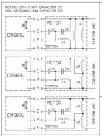
The bad head had a hard time starting, but runs well if I take the fan cover off and help it along with my hand. Once it's going, it goes. First thing, I checked out the start capacitor which was located in the control box along with the breaker switch and run capacitor. It checked out on the multimeter (it has a capacitor function that measures capacitance), but I double checked it by switching capacitors between heads. This didn't help the bad head, so I figure I'm left with a bad centrifugal switch or a burned up starter winding (this is the single-phase electric motor rebuild I've ever attempted).
So now I'm taking the motor apart, but can't seem to figure out how I'm going to get the pump body off the motor. The heads, and valve bodies came off easily (all the o-rings looked like they'd have to be replaced), but I stalled trying to pull the crankshaft off the motor shaft. As you can see from the pictures, I broke an M10 puller bolt off in the center hole trying to remove it with a homemade puller I made from a piece of H-beam ('wide flange beam' for the engineers) I set across the front of the pump body.
I haven't removed the motor thru bolts because they can't be taken out with the pump body on, so I started soaking the crankshaft/motor shaft fitting in PB blaster in preparation for my next attempt at pulling the crank off.
Before I continue though, I wanted to poll you guys for how best to proceed. I'm a little worried that if I get the crank off (which seems to be a two piece design based on the fact that the piston rods are a one-piece design) I won't be able to press it back on to the correct depth/height if there's no positive stop to keep me from pressing it too far; this whole thing reeks of high-tolerance measurements.
An alternative I'm considering is cutting the thru bolts and drilling out the threads the far end. Then making my own thru bolts from a piece of round-stock and threading both ends so I can use nuts on both ends.
So... should I keep trying to pull the crankshaft off, or should I go ahead and start cutting bolts? I'm afraid I won't be able to put the crank on properly if I get it off, but I'm also afraid that I won't be able to take the motor apart to get at the centrifugal switch with just the thru bolts off and the pump body still on.
annotated album on imgur
I was looking for aftercoolers and air dryers on craigslist when I came across a dentist selling his old Air Techniques Airstar 5 compress with one bad head for the steep sum of $150.
After reading this thread and not finding a good reason to risk it. I brought it home and set about to fix the bad head. One head ran like a champ, so I had something to compare the bad one too. Sadly, there's not much information out there about these compressors as far as service and parts (the parts I did find are incredibly expensive!).
The bad head had a hard time starting, but runs well if I take the fan cover off and help it along with my hand. Once it's going, it goes. First thing, I checked out the start capacitor which was located in the control box along with the breaker switch and run capacitor. It checked out on the multimeter (it has a capacitor function that measures capacitance), but I double checked it by switching capacitors between heads. This didn't help the bad head, so I figure I'm left with a bad centrifugal switch or a burned up starter winding (this is the single-phase electric motor rebuild I've ever attempted).
So now I'm taking the motor apart, but can't seem to figure out how I'm going to get the pump body off the motor. The heads, and valve bodies came off easily (all the o-rings looked like they'd have to be replaced), but I stalled trying to pull the crankshaft off the motor shaft. As you can see from the pictures, I broke an M10 puller bolt off in the center hole trying to remove it with a homemade puller I made from a piece of H-beam ('wide flange beam' for the engineers) I set across the front of the pump body.
I haven't removed the motor thru bolts because they can't be taken out with the pump body on, so I started soaking the crankshaft/motor shaft fitting in PB blaster in preparation for my next attempt at pulling the crank off.
Before I continue though, I wanted to poll you guys for how best to proceed. I'm a little worried that if I get the crank off (which seems to be a two piece design based on the fact that the piston rods are a one-piece design) I won't be able to press it back on to the correct depth/height if there's no positive stop to keep me from pressing it too far; this whole thing reeks of high-tolerance measurements.
An alternative I'm considering is cutting the thru bolts and drilling out the threads the far end. Then making my own thru bolts from a piece of round-stock and threading both ends so I can use nuts on both ends.
So... should I keep trying to pull the crankshaft off, or should I go ahead and start cutting bolts? I'm afraid I won't be able to put the crank on properly if I get it off, but I'm also afraid that I won't be able to take the motor apart to get at the centrifugal switch with just the thru bolts off and the pump body still on.
annotated album on imgur