To avoid these ads, REGISTER NOW!

Redoing a bench grinder, need to splice old wiring

larryq

Well-known member
Joined
Jul 12, 2011
Messages
2,421
I picked up an old bench grinder that I'm going to replace the bearings on and repaint. I had to cut some of the wires to get it apart, and need to splice them back together.

What would you recommend in this case-- stripping, then soldering the two halves together, with a heat-shrink tube over them? I've done hack work wiring repair before, crimping and such, but the spaces I'm dealing with now are a little tight, and I don't want to extend the wiring much if I can help it, since it's in an enclosed space which will have a spinning rotor nearby. Too much slack and I can see things going bad.

That said, I'm open to suggestions. The existing wiring is covered in a sort of cloth tape, which gives an idea on how old the grinder is. It worked fine before I took it apart so the connections were still good.
 
To avoid these ads, REGISTER NOW!

mayday0017

Well-known member
Joined
Oct 20, 2010
Messages
1,715
Location
Houston Texas
I would figure out how the factory did it in the first place... odds are if it didn't have a splice it doesn't need one...
 

GarageWarrior

Well-known member
Joined
Oct 31, 2012
Messages
378
Location
Westerly, RI
Larry, what gauge wires are you dealing with? I've been using jewelry bead crimper and crimps for 18-30 gauge wire. Those make high-strength connections that are much more compact than the Western Union solder splice
http://en.wikipedia.org/wiki/Western_Union_splice

Crimped connections are also preferable to soldering in high-vibration applications

For bead tube crimping this is what you'd need:

http://www.amazon.com/dp/B000SNBC8I/?tag=atomicindus08-20

http://www.amazon.com/dp/B001FD3BAM/?tag=atomicindus08-20

More info here:
http://www.beadalon.com/BaseCrimpTubes.asp

For insulation - heat shrink tubing, as was suggested earlier.
 
OP
L

larryq

Well-known member
Joined
Jul 12, 2011
Messages
2,421
Thanks for your suggestions...hadn't heard of bead crimping before but it looks interesting. As to the size of the wire, I don't have it in front of me but I'd guess 14 ga?
 
To avoid these ads, REGISTER NOW!

2ManyProjects

Well-known member
Joined
Jul 18, 2013
Messages
757
I picked up an old bench grinder that I'm going to replace the bearings on and repaint. I had to cut some of the wires to get it apart, and need to splice them back together.

What would you recommend in this case-- stripping, then soldering the two halves together, with a heat-shrink tube over them?

Depending on the space you have to work with, that MAY be your "least evil" solution; but I would be hard pressed to call it "ideal".

(Before going any further, note that I am presuming that the unit was originally equipped with a plug-in power cord; hence, this is all stranded wiring we're talking about.)

The potential problem is, any time you solder two twisted-together stranded conductors, the solder WILL wick its way "upstream" (so to speak) on each side of that connection, fusing the individual strands of each conductor together into a solid mass for some (possibly small, but still) distance on each side of the splice. This creates a "stress riser" point where the solder stops, so that any subsequent flexing of the wires (due to vibration, etc.) is concentrated at that point; eventually, metal fatigue sets in, and... You can imagine the rest.

If you do go this route, use at least two (maybe more) layers of progressively larger heat-shrink tubing over the splice, with each layer an inch or so longer than the one under it, in order to form what might be called a "poor man's stress relief". The bottom (or "first") layer of tubing should itself be long enough to more than span the "solder wicked" portion of the wires. The idea is for the HS tubing to both somewhat resist the flexing force, and spread it out over a larger area.

That said, I'm open to suggestions. The existing wiring is covered in a sort of cloth tape, which gives an idea on how old the grinder is. It worked fine before I took it apart so the connections were still good.

If you can get to the original connection points (presumably on the motor), a better approach would be to remove all remnants of the original wiring; then run your new wiring directly to those points, with no splicing at all. How feasible this may be will depend somewhat on the type of connections they originally used (rivets could be a problem, for example).

 
OP
L

larryq

Well-known member
Joined
Jul 12, 2011
Messages
2,421
If you can get to the original connection points (presumably on the motor), a better approach would be to remove all remnants of the original wiring; then run your new wiring directly to those points, with no splicing at all. How feasible this may be will depend somewhat on the type of connections they originally used (rivets could be a problem, for example).


Thanks for your detailed post. I'd love to pull out the original wiring and replace it, but parts of it are embedded deep in the windings and others are soldered in awkward locations, behind folds in the casing, and hard to get to.

I should have included pics earlier, and will do so tonight, to show better what I'm dealing with.
 
OP
L

larryq

Well-known member
Joined
Jul 12, 2011
Messages
2,421
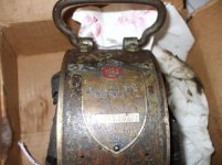
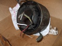
Here are some pics of what I've got. I was way off on the wire gauge, it's more like 10 ga instead of 14. I painted each wire before I cut it so as not to misalign them when splicing back together.

Note how the red and white ones connect to the housing, and will be near the shaft when it's spinning. That's one reason I'd like to splice in as little extra wiring as possible, to minimize the chances of the shaft brushing against them. (Also, things are greasy in the photos because I used a bit of Kroil to get the housing apart.)

Thanks again to everyone who's posted so far-- I'm new to soldering and/or real wiring repair and every bit of advice helps!
 

Attachments

  • DSCF1632.jpg
    DSCF1632.jpg
    132 KB · Views: 30
  • DSCF1633.jpg
    DSCF1633.jpg
    144 KB · Views: 31
  • DSCF1634.jpg
    DSCF1634.jpg
    133.3 KB · Views: 28
  • DSCF1635.jpg
    DSCF1635.jpg
    137.9 KB · Views: 27
  • DSCF1631.jpg
    DSCF1631.jpg
    139.4 KB · Views: 29

MTW

Well-known member
Joined
Aug 6, 2013
Messages
294
Location
SE Michigan
Looks to me from the pics that you posted that those motor winding leads connected to insulated posts in the endbell of the motor. Too late now, but it would have been best to disassemble those insulated posts and remove the winding lead from it intact.

Internal motor winding leads and splices are normally done by brazing them with a torch, similar to freon piping, then insulated with fiberglass tape, before varnish dipping the winding.

In machine motor connections is is common practice to use ring terminals. Put a uninsulated ring terminal on all wires, and then bolt them together, with a very short screw and nut. When bolting together place the rings back to back, so that the wire barrels face away from each other to get them to lay flat with each other, and reduce the profile. Insulate with a quality electrical tape that will not come loose with heat, (3M 33+)

This way the connection is serviceable in the future and resistant to heat and vibration. Solder is never a good idea in a high heat, high current, high vibration environment. Its been done this way for the last 70 years.
 
To avoid these ads, REGISTER NOW!
Top Bottom