Remote spin on filter and cooler.
This took a lot of work, I had to modify the right side engine cover, machine up a new cover for the now gone strainer, machine a spin on filter mount, fabricate some new engine mounts to hold the mount, fabricate a mount for the cooler, machine up a few stainless fittings for the mod, plus a few other bits and pieces.
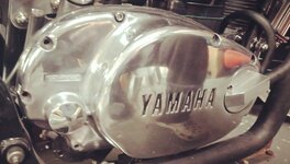
I drilled and tapped the front of the sidecover. I hate jobs like this, there's always the fear of stuffing it up and ruining a part, but, all went well: drilled out the oil pump gallery to 10.8mm, tapped it to M12 x 1.25 for 40mm to cover the gallery to the old oil strainer, countersunk the top of the hole to allow for an O ring and inserted the stainless spigot I turned up, looks quite alright.
Whilst I had the cover off, I removed the kickstart mechanism and turned up a couple of bungs to cover the hole.
Next I binned the strainer cover and machined up a new one, which I think looks a lot better than just screwing a right angle, screw in fitting on the original part. Took a bit of doing this part as the outer side had to be angled to follow the angle of the side cover. Rather than use an ugly screw in fitting, I spun up a stainless barb and shrunk it in place.
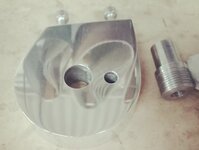
Next came the spin on filter mount. I made this from a lump of 25mm ally, shaped it to the desired shape, drilled and tapped the side for mounting screws, then mounted it in the lathe to machine the oil gallery recess, once done I drilled a central hole for oil intake and a second hole through to the recess for the output. I then spun up a threaded piece on which to spin the filter, shrunk fit it into the housing, turned up a stainless, threaded barb, screwed it into the spin on filter threaded piece, sandwiching the filter mount between. There was insufficient space for a screw in output barb, so I spun up a barb for an interference fit and pressed it into place.
For my next trick I fabricated some new engine mounts on which to mount the filter mount and oil cooler. The engine mounts were basically the same as the original ones I made, the right has been extended downward around 25mm for the filter mount and both drilled and tapped at the front edge for mounting a cooler bracket.
The cooler bracket is just a piece of 3mm ally bent at a right angle so the cooler mounts on top. I had to cut some 10mm ally tube to fit between the cooler mounting fins and recess the mounting bracket holes a little so I could install some rubber grommets to insulate the cooler from vibration. To hold it in place I cut some 6mm bolts to size and spun up some threaded positive stop, ally T nuts.
Last of all, I polished everything - of course!
This took a lot of work, I had to modify the right side engine cover, machine up a new cover for the now gone strainer, machine a spin on filter mount, fabricate some new engine mounts to hold the mount, fabricate a mount for the cooler, machine up a few stainless fittings for the mod, plus a few other bits and pieces.
I drilled and tapped the front of the sidecover. I hate jobs like this, there's always the fear of stuffing it up and ruining a part, but, all went well: drilled out the oil pump gallery to 10.8mm, tapped it to M12 x 1.25 for 40mm to cover the gallery to the old oil strainer, countersunk the top of the hole to allow for an O ring and inserted the stainless spigot I turned up, looks quite alright.
Whilst I had the cover off, I removed the kickstart mechanism and turned up a couple of bungs to cover the hole.
Next I binned the strainer cover and machined up a new one, which I think looks a lot better than just screwing a right angle, screw in fitting on the original part. Took a bit of doing this part as the outer side had to be angled to follow the angle of the side cover. Rather than use an ugly screw in fitting, I spun up a stainless barb and shrunk it in place.
Next came the spin on filter mount. I made this from a lump of 25mm ally, shaped it to the desired shape, drilled and tapped the side for mounting screws, then mounted it in the lathe to machine the oil gallery recess, once done I drilled a central hole for oil intake and a second hole through to the recess for the output. I then spun up a threaded piece on which to spin the filter, shrunk fit it into the housing, turned up a stainless, threaded barb, screwed it into the spin on filter threaded piece, sandwiching the filter mount between. There was insufficient space for a screw in output barb, so I spun up a barb for an interference fit and pressed it into place.
For my next trick I fabricated some new engine mounts on which to mount the filter mount and oil cooler. The engine mounts were basically the same as the original ones I made, the right has been extended downward around 25mm for the filter mount and both drilled and tapped at the front edge for mounting a cooler bracket.
The cooler bracket is just a piece of 3mm ally bent at a right angle so the cooler mounts on top. I had to cut some 10mm ally tube to fit between the cooler mounting fins and recess the mounting bracket holes a little so I could install some rubber grommets to insulate the cooler from vibration. To hold it in place I cut some 6mm bolts to size and spun up some threaded positive stop, ally T nuts.
Last of all, I polished everything - of course!
Attachments
-
 tapping the side cover.jpg164.3 KB · Views: 24
 -
 oil cooler and barbs.jpg136.3 KB · Views: 24
 -
 engine mounts oil filter housing complete.jpg163.3 KB · Views: 24
 -
 oil filter housing inner.jpg159.4 KB · Views: 24
 -
 oil filter housing outer.jpg114.2 KB · Views: 23
 -
 oil inlet cover inside comparo.jpg158.6 KB · Views: 23
 -
 oil inlet cover outer.jpg208.9 KB · Views: 25
 -
 remote filter cooler fitted right.jpg252.4 KB · Views: 27
 -
 remote filter cooler fitted right 2.jpg234.8 KB · Views: 26