CARS
Well-known member
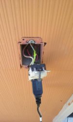
Hello. I'm helping my friend put a receptacle in a box that currently has a switch on the outside of her house. Hopefully I can put this into words.
The switch on the outside is tied together with a switch on the inside by the back door and it controls a motion light.
There are 3 wires to the outside switch. Red, Black, and White. (the box is grounded but there was no green wire to the switch )
)
When I put a meter on the wires, I get 120V between the Red and White with the switch in one position, and 120V between the Black and White when it's in the other position.
Is there any way I can use this configuration to get an outlet to work (switched or not)?
It's a remodeled 1890's brick home and as you can imagine it would be almost impossible to run a new circuit to this box.
The switch on the outside is tied together with a switch on the inside by the back door and it controls a motion light.
There are 3 wires to the outside switch. Red, Black, and White. (the box is grounded but there was no green wire to the switch
)When I put a meter on the wires, I get 120V between the Red and White with the switch in one position, and 120V between the Black and White when it's in the other position.
Is there any way I can use this configuration to get an outlet to work (switched or not)?
It's a remodeled 1890's brick home and as you can imagine it would be almost impossible to run a new circuit to this box.
")