To avoid these ads, REGISTER NOW!

Running 2 or more RPC into a 3 phase panel

930dreamer

Super Moderator
Staff member
Joined
Oct 7, 2009
Messages
23,046
Location
Amarillo,TX and Stinnett,TX
Hello, I have a 10 hp and a 7.5 hp 3 phase rotary phase converter I want to feed into a 3 phase panel. The panel is a ITE 100 amp. I control the two RPC with disconnects now.

Question is, the cable LINE IN lugs are huge, can they be reduced?
I plan to add a third idler motor also, all operate unloaded, how do I size the wire to the panel? All are wired in Parallel.
10HP- 26.0 FLA
7.5 - 22.3 FLA
7.5 - 22.3 FLA or 15HP-40 FLA.

Thanks
 
To avoid these ads, REGISTER NOW!

oltruckag

Well-known member
Joined
Aug 10, 2007
Messages
171
Location
*******, GA
ok - I'm not a RPC expert but I'm good with 3phase... How are you going to synchronize the converters? I'm thinking that is going to be an expensive proposition. I think you either have to run each machine off it's own RPC or have a single RPC big enough to run the machines you have.

If it's easier than that I'll learn something today, but I'm highly doubtful it is simple or cheap. Generator synchronizing gear isn't cheap, and this is basically the same thing - electrically driven generators.
 

mrb

Well-known member
Joined
Dec 31, 2008
Messages
3,734
are the shafts all coupled together to keep them in sync? i too am curious how you parallel these things...
 

A_Pmech

Well-known member
Joined
May 8, 2007
Messages
8,002
Location
IL
Paralleling converters is easy. First you start the largest converter, then you start the second converter using the first, just as if it was a load motor. By design, they're in synch. Every motor you add to the system increases the available current on the third phase, so long as it is not fully loaded in which case it starts to sink current from the third phase.

Obviously, ensure that the single-phase side controls for the largest converter will handle the power that will be sunk into the second converter.
 
OP
9

930dreamer

Super Moderator
Staff member
Joined
Oct 7, 2009
Messages
23,046
Location
Amarillo,TX and Stinnett,TX
Well I started the 10 & 7.5 RPC's and fed them into the 3 phase panel. I had wired a 15 hp idler into the 3 phase panel using one of the breakers also. I can't start the 15 hp idler, I popped one of the disconnect fuses. I will need to upgrade the wiring and remove the disconnects from each idler(30Amp each). What's the correct way to run the idlers into a 3 phase panel and still have the motor/circuit protection?
 
To avoid these ads, REGISTER NOW!

OldCarGuy

Well-known member
Joined
Nov 29, 2005
Messages
2,020
Location
Ohio
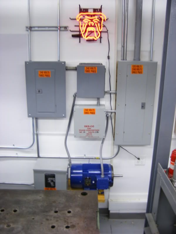
My Power Distribution Center in my Garage Shop,,, 240 Volt 200 Amp single phase main load center. And a 100 Amp 240 Volt three phase load center fed by one 5 HP and onr 10 HP Rotary Phase Converters. They are set up to run either one at a time or both in tandem for maximum three-phase output. The center top box encloses the switching relays so that I don‘t get any feedback to one of the RFC that is not running while I‘m running the other.

The only cincern about phasing the two idler motors is that the primary and secondary wires are in the same order.

I now have a total 22 motors on 12 machines that can run off them. Ranging from 1/ 4 HP to 7.5 HP. I was told that my 7.5 HP lathe would require a 15 HP rotary inverter to run. But was told I could run the two inverter to achieve that rating. The fact is it will start up and run all day without any problems on the 10 HP inverter. In fact I neglected to switch over to the bigger inverter one time. And started and ran the 7.5 HP lathe for hours on the 5 HP RFC. Which I wouldn’t recommend. But it never caused any problems.
__________________


DSCF0592-1.jpg
 

A_Pmech

Well-known member
Joined
May 8, 2007
Messages
8,002
Location
IL
From the single phase panel.

The single phase supply wiring should be sized for an equivalent power single-phase motor. Remember that you're taking 10HP (or whatever your idler is) worth of single phase on two wires and splitting it up into three phase on three wires. Thus the input wires to your converter must be larger than the output wires. The output wiring in a single-converter system would normally be sized for the 3-phase FLA of the idler motor.

Voltage being equal, you can get a good idea of what the system will draw on single phase by multiplying the idler 3-phase FLA times the square root of 3, which is 1.73.
 
To avoid these ads, REGISTER NOW!
Top Bottom