To avoid these ads, REGISTER NOW!

sears Craftsman Grinder illuminated toggle switch wiring Problem

darkangelman1

Member
Joined
Nov 14, 2014
Messages
11
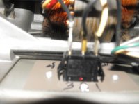
my toggle switch on my sears craftsman bench grinder recently just fell apart in my hands probably from old age. it was a 15amp switch from what was marked on it. the lowest amp i could find new that was closest to it was a g&b red illuminated 16 amp at farm and fleet. everything i found was a 20 amp. any way after wiring it all back to together i cannot get the grinder light to come one when the grinder is on. i honestly don't know if it did in the original factory wiring position as i never used it. I've rewired it in every configuration i can think of. either when i wire it together nothing works at all, or the light works only, or the grinder works only. the toggle switch will be lighted up all the time, or it will be on only when i flipped in the on position. the new new switch has three plugs just like the old one did and they are labeled 1 2 3. in the way it is wired now this is the only i can get the grinder to come on. the white wire coming from the power cord is on the 1 position, the black wire coming from the power cord is in the 2 position and the longest wire coming from the light is on the 3 position. both wires coming from the light are black and the shortest one goes to the capacitor i think that's what it is. as soon as i plug in the grinder the toggle switch lights up without me turning it on. is that normal? i always thought they weren't supposed to light up until you turn them on. any help will be appreciated i don't know where else to look for help as i have seen so many nice grinders on here. also i don't know what model this is because the info on the front sticker has long faded off. the red serial number remains 709600070 but i don't what year it is made. it was my grandfathers than my dad's and now i inherited when he passed on. i want to keep it running as it holds a lot of sentimental value to me. so any help i can get will be appreciated. if i am posting this in the wrong page please free to move to the right area too. I've got pics of what it looks like inside the are a little grainy as my camera doesn't have auto focus so i apologize for that. is there a site that i can look up the serial number on?
 

Attachments

  • 2.jpg
    2.jpg
    149 KB · Views: 40
  • $_57.jpg
    $_57.jpg
    140.3 KB · Views: 40
  • DSCF0042.JPG
    DSCF0042.JPG
    130.2 KB · Views: 39
  • DSCF0047.JPG
    DSCF0047.JPG
    129.2 KB · Views: 30
  • DSCF0052.JPG
    DSCF0052.JPG
    129.2 KB · Views: 27
  • DSCF0057.JPG
    DSCF0057.JPG
    130.6 KB · Views: 28
  • DSCF0044.JPG
    DSCF0044.JPG
    126.4 KB · Views: 32
Last edited:
To avoid these ads, REGISTER NOW!

nehog

Well-known member
Joined
Jan 2, 2010
Messages
7,935
Location
Jaffrey, NH
Also confirm the switch (light) is rated at 120 volts. Many of those are 12V for automotive use.
 
OP
D

darkangelman1

Member
Joined
Nov 14, 2014
Messages
11
ok i reedited the post and put 2 pics up of the switch i put in i hope i got the right switch. they are located up above in the original posting.

this is how its wired up currently:

i got the white wire coming from the cord on the 1 slot (line cable). the black wire coming from the cord on the number 2 slot (acc or called load on this switch diagram). and the long cord coming from the light n the number 3 slot (neutral)

grinder comes on but no light works at the same time.

switch is only a on/ off switch, no middle or speed setting
 
Last edited:
OP
D

darkangelman1

Member
Joined
Nov 14, 2014
Messages
11
honestly i dont know if the white is a hot wire or the black one is, or what the neutral or ground is. there is a green wire screwed down on the casting of the grinder so white, black and green coming from the cord.
 

G_P

Well-known member
Joined
Jul 11, 2010
Messages
7,135
Location
Central CT
White wire should be neutral. Black wire should be hot. Green is ground and will be attached to the metal case of the grinder.
Terminal 1 goes to the black wire from the power cord.
Terminal 2 goes to the black wire coming out of the grinder motor.
Connect the white wire from the power cord to the white wire from the grinder motor, then run a pigtail from that to Terminal 3 of your switch.
 

abk241

Well-known member
Joined
Aug 22, 2014
Messages
310
Location
SF Bay Area, California
does that account for the two black wires coming out of the light?

If you follow G_Ps directions for wiring, the grinder should work properly and the switch, if illuminated, should light up when flipped on.
As for the 2 wires going to the grinder work light...hook 1 wire up to terminal 2 and the other to terminal 3.
This will bring power to the light only when the grinder power switch is on.
 
To avoid these ads, REGISTER NOW!

G_P

Well-known member
Joined
Jul 11, 2010
Messages
7,135
Location
Central CT
If the grinder has a work light, Connect the wires from the light to the wires from the grinder motor. This way the light will be on any time the grinder is running.
 
OP
D

darkangelman1

Member
Joined
Nov 14, 2014
Messages
11
ok everybody i finally managed to get some in focus pics, i hope this helps you help me. i didn't want to work on my problem until you had a chance to look at better pictures of the grinder insides. thanks for your time and advice and help.
 
Last edited:
OP
D

darkangelman1

Member
Joined
Nov 14, 2014
Messages
11
do i need a better switch? i got it at farm and fleet in the electrical department not the automotive department. its a 16 amp where the old one was only a 15 amp i wanted to stay closer to the original as possible.
 

yeldogt

Well-known member
Joined
Jan 2, 2012
Messages
18,184
First -- does the switch light up when the unit is turned on? Is that the light you are talking about? If so ....then then that is what the white wire is for on the switch. An normal switch would only have the hot from the cord going to the motor/control ... a light switch needs the white to illuminate the switch.

Does the grinder have a light on top to illuminate the wheels? Normally this is tired into eh motor and goes on with the motor.

Is this a two speed unit?
 
OP
D

darkangelman1

Member
Joined
Nov 14, 2014
Messages
11
just one speed always has been. there are 2 white wires one comes off the motor winding and the other main power cord.the light is supposed to come on when the switch is flipped turning the grinder on. I've rewired it in every configuration i can think of. either when i wire it together nothing works at all, or the light works only, or the grinder works only. the toggle switch will be lighted up all the time, or it will be on only when i flipped in the on position. the new new switch has three plugs just like the old one did and they are labeled 1 2 3. in the way it is wired now this is the only i can get the grinder to come on. the white wire coming from the power cord is on the 1 position, the black wire coming from the power cord is in the 2 position and the longest wire coming from the light is on the 3 position. both wires coming from the light are black and the shortest one goes to the capacitor i think that's what it is. as soon as i plug in the grinder the toggle switch lights up without me turning it on. the lite
has 2 black wires on it and i put them back where they were originally. the motor now turns on but no light, if i flip the wires on the switch around the light works but no grinder.
 

RickP

Well-known member
Joined
Jan 15, 2013
Messages
1,561
Location
Annapolis, MD
I'm looking at the new switch you bought and wondering if it's designed to be illuminated all the time. Have you tested it with a power cord and a voltmeter?

You might be wiring everything correctly and the switch is just different than the original switch. You could buy a different switch - those 20 amp switches would work fine.
 
OP
D

darkangelman1

Member
Joined
Nov 14, 2014
Messages
11
no i dont know how to do that. makes me wonder if there is a switch that lets you have the light on and the grinder on at the same time
 

RickP

Well-known member
Joined
Jan 15, 2013
Messages
1,561
Location
Annapolis, MD
I just looked on the manufacturer's website for that switch:
Tech Data PDF

It looks like the new switch works like this: switch illuminated when the motor is running.

It seems to me that the new switch might have been wired differently than the original. Is it possible that the wires coming from the power supply cord got unhooked and swapped?

I can't figure out a wiring combination that will work with that switch. I think you should bypass the switch and use jumpers to figure out how the motor wires should be connected. If you draw a simple wiring diagram of what works we should be able to help you more.

Be very careful with the jumpers and stay safe. Good luck!
 
Last edited:
To avoid these ads, REGISTER NOW!
Top Bottom