To avoid these ads, REGISTER NOW!

Service Body build

racingtadpole

Well-known member
Joined
Dec 3, 2011
Messages
2,029
Location
The far side of crazy.. but sometimes Australia
Greetings Everyone :)

I got a quote a couple of months ago for a lift off service body similar to this one (the one linked is a fixed one but you get the idea).

http://gitsham.com.au/index.php?pag...facturer_id=0&option=com_virtuemart&Itemid=56

The quote was well, lets say enough to make me start a build thread.

So after a bit of thought, Ive decided I want 3 doors like the one in the link.

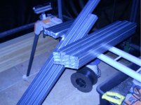
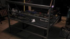
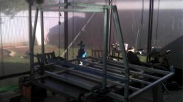
Construction will be a galvanised square/rectangle tube steel frame skinned with aluminium sheet (had planned on all aluminium construction until the quote came back for the materials).

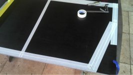
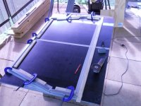
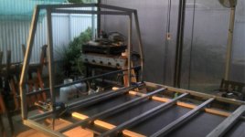
Heres a drawing of the base and the most complicated of the 4 frames I need to make. The front one needs to be made like the diagram, the rear one needs to be made without the two centre verticals and I need two middle ones without any internal verticals. Not really rocket science.

So here we go...
 

Attachments

  • Front.jpg
    Front.jpg
    122.2 KB · Views: 104
To avoid these ads, REGISTER NOW!
OP
R

racingtadpole

Well-known member
Joined
Dec 3, 2011
Messages
2,029
Location
The far side of crazy.. but sometimes Australia
Tonights effort.

Bought an 1800 x 1200 x 17 sheet of waterproof form ply from the hardware store and started layout. The tape Im using to see my marks gives some idea of the shape.

The sheet of ply will be cut to form part of the floor when the frame is finished.
 

Attachments

  • Layout1.jpg
    Layout1.jpg
    29.9 KB · Views: 66
  • layout2.jpg
    layout2.jpg
    36.3 KB · Views: 68
Last edited:

kald

Well-known member
Joined
Mar 31, 2012
Messages
672
Location
Central Fl
Very nice! Can't wait to follow the build. I would be conscious of weight and center of gravity with this build even if you use a larger truck.

edit: Cool website in that link. You typically don't see light trucks decked out with service bodies much here in the US.
 
Last edited:

anotherjoe

Member
Joined
Apr 2, 2013
Messages
10
looks cool, what kinda truck is it going on? I was going to build one of these at one point but after specing it out, it got real heavy real fast.
 

theoldwizard1

Well-known member
Joined
Feb 22, 2011
Messages
43,145
Location
SE MI
I saw this on the 'net.

Like you, ambulances bodies use aluminum tubing as the frame, but they attach the sheet aluminum to it with continuous strips of double sides tape ! 3M make several different kinds so you will need to do some research.
 
OP
R

racingtadpole

Well-known member
Joined
Dec 3, 2011
Messages
2,029
Location
The far side of crazy.. but sometimes Australia
Very nice! Can't wait to follow the build. I would be conscious of weight and center of gravity with this build even if you use a larger truck.

edit: Cool website in that link. You typically don't see light trucks decked out with service bodies much here in the US.

looks cool, what kinda truck is it going on? I was going to build one of these at one point but after specing it out, it got real heavy real fast.

This is going to be interesting to watch. Sorry if I missed it but what vehicle is it going to be fitted to ?

There's a bit of weight in it. Rough numbers has the steel frame at around 40Kg. Then theres the skin, floor, door frames, door skins, gas struts/seals/locks. Probably double that (and maybe a bit more) when done.
It'll lift the centre of gravity a bit, but not a huge amount, at least not enough to make it dangerously unstable. Better not make it too heavy, the car only has 53kW at the rears (after the turbo kit went on) :lol:

I saw this on the 'net.

Like you, ambulances bodies use aluminum tubing as the frame, but they attach the sheet aluminum to it with continuous strips of double sides tape ! 3M make several different kinds so you will need to do some research.

After doing some research on some of the suggestions in the glue thread I started a couple of weeks ago I have decided to glue the skin on with a Sikaflex adhesive. That decision was based largely on availability. I can get the Sika flex quite easily (and quite cheaply as it turns out) where as the 3M stuff is a bit more exotic (reflected in the price and lead time). Also planning to put a few rivets in, just to make sure.

Its going on a 1998 Ford Courier Dual Cab (Mazda B series with Ford badges on it). Couple of pictures of truckasaurus for your viewing pleasure. The tray was made by Gitshams in Adelaide, the company I linked to.
 

Attachments

  • Utefromside.jpg
    Utefromside.jpg
    56.7 KB · Views: 72
  • Ute from back.JPG
    Ute from back.JPG
    53.8 KB · Views: 55
OP
R

racingtadpole

Well-known member
Joined
Dec 3, 2011
Messages
2,029
Location
The far side of crazy.. but sometimes Australia
Tonights progress

After a bit of rooting around as a result of breaking my $2 plastic protractor a couple of weeks ago I now have a set of cutting templates for the outside of the frame.

Oh and I also have a sliding compound saw that now needs repairs. Went inside to get the green bottle in the last picture, heard a massive crash, went back outside to find the mitre saw **** up on the ground having just stage dived off its stand. My first thought was witch dog had tried to jump onto the stand but she wasn't anywhere in the near vicinity.

Tommorow afternoon plan is to get some metal, then figure how Im actually going to cut it (my friction saw was stolen last year). Also need to cut some timber strip to screw to the board to clamp to while everything is welded.

And for those of you who find country of origin important. The bevel is made by Johnson Measure in the US, the Square is by Empire made in the US, the clamps are British made Record, the straight edge I use is a German made Stabila and my tape measure is an Australian made Lufkin. Oh and the beer is Australian too if you count Tasmania as part of Australia :lol:
 

Attachments

  • Stagedivesaw.jpg
    Stagedivesaw.jpg
    57.1 KB · Views: 92
  • Joint.jpg
    Joint.jpg
    46.9 KB · Views: 57
  • Cuttingtemplates.jpg
    Cuttingtemplates.jpg
    45.1 KB · Views: 56
  • Anglefindingnoprotractor.jpg
    Anglefindingnoprotractor.jpg
    44.3 KB · Views: 57
Last edited:

kald

Well-known member
Joined
Mar 31, 2012
Messages
672
Location
Central Fl
That looks like a nice bed you already have. Couldn't you just make a topper for that? And what is the siding made out of? It looks pretty cool.
 
OP
R

racingtadpole

Well-known member
Joined
Dec 3, 2011
Messages
2,029
Location
The far side of crazy.. but sometimes Australia
Just saw this, should be interesting. I like your truck.
b.t.w. Adam, that is no way to treat your miter saw, mate!

Not really sure what happened. One minute it was clamped up to the stand, next minute it was laying on the floor. It tried to do the same thing a few months ago too, but I was there to catch that one. Think Im going to remove the retainers out of the frames and weld the frames to the stand. The saw is really nice, the stand is built to a price.

That looks like a nice bed you already have. Couldn't you just make a topper for that? And what is the siding made out of? It looks pretty cool.

The sides are proprietry profile that Gitsham produce in house for their bodies. The rear ladder bar in the picture lifts out, and although you probably cant see it very well the sides slide off too. Plan is to put this thing on top of the tray as a seperate 'pod'. It has to be removable so I can still use the car as you see it in the pictures. The link to TSB below probably shows what Im trying to build a bit better
http://www.tsb.net.au/service-bodies/lift-off/Lift-Off-Canopy/

Thanks for the interest everyone, it'll get more interesting once I start chopping up some metal.
 
To avoid these ads, REGISTER NOW!
OP
R

racingtadpole

Well-known member
Joined
Dec 3, 2011
Messages
2,029
Location
The far side of crazy.. but sometimes Australia
Hello everyone :)

Pleased to report forward progress.
I had been wondering how I was going to cut the tube up, well the universe sorted things out for me. The morning after my last update I was sitting on the back step drinking my morning coffee and decided to have a look at Gumtree (our equivalent to Craigslist and Kijiji) aaaaaaaaaaaaaaannnnnnnddddddd.... I found a bandsaw. :rocker:

Didnt get it for quite the steal that some of the others Ive seen on here picked up for, but I did pretty well considering I didnt really haggle.

So after I got raped by the local saw doctor for a couple of blades (two bimetal varipitch and two carbon steel blades cost nearly as much as the saw itself) and then wasted a couple of hours of my life getting the thing to cut as true as it ever will without any modifications I set it to work.

The 6.5m length of 40x40 square that was laying under the carport with the VW transaxle that put me in hospital a couple of weeks ago (long story) has now been docked to slightly oversize for the frame. Also had enough daylight left to cut the 38x25 into shorts and mitre the angles for where the roof meets the side.

Hoping to get the rest of the 38x25 mitred before the weekend so I can take a day off from other stuff and start welding :bounce:
 

Attachments

  • Mitred Steel.jpg
    Mitred Steel.jpg
    52.6 KB · Views: 36
  • Steel Docked.jpg
    Steel Docked.jpg
    48.7 KB · Views: 37
  • Bandsaw.jpg
    Bandsaw.jpg
    44.5 KB · Views: 45

NASTYZEN

Well-known member
Joined
Jun 11, 2010
Messages
2,823
Location
St-Colomban,Que. Canada
Nice saw Adam. I have the same one and yes, bi metal is the way to go.Try to use more teeth than fewer and the blade should pop off less.
They go for about 300 bucks new around here.
 

kald

Well-known member
Joined
Mar 31, 2012
Messages
672
Location
Central Fl
That thing will never cut true. We had one just like that I gave away about 10 years ago. That irritating *******, my blood pressure jut went up looking at yours :)
 
OP
R

racingtadpole

Well-known member
Joined
Dec 3, 2011
Messages
2,029
Location
The far side of crazy.. but sometimes Australia
Got it pretty close, planning to mod it when I have some time. Even with the guide rollers fully extended they are too close to the drive wheels to allow it to transition to completely flat. They are also too far from the work which just compounds things. But I do have it cutting to well within a mm of plumb, rough enough for the bush for this job :)
 
Last edited:
OP
R

racingtadpole

Well-known member
Joined
Dec 3, 2011
Messages
2,029
Location
The far side of crazy.. but sometimes Australia
Hello Everyone :)

More forward progress, well sort of....

I got the rest of the tube cropped during the week and got to it..

Screwed some timber to the board to use as clamping guides, sanded some galv off the tube (more on that in a moment) clamped it down and got to it... and then started to say a lot of rude words...

Normally I would dunk the ends of the tube in a bucket of brickies acid to strip the glav off both the outside as well as the inside. I dont have any brickies acid in the shed at the moment and decided I couldnt be bothered going and getting some, so I sanded the ends. It welds perfectly until... I reach the seam in the tube. Once I get to the seam the puddle collapses and leaves a gaping great hole. On every single weld its exactly the same. I tried marking the seam and pushing the pedal a bit harder just on the edge of the seam, that just made a bigger hole. I tried letting up on the pedal, that made a marginally smaller hole. At that point I stopped because things werent going my way. Im surmising that because there is still galv on the inside its being drawn up into the puddle as the puddle approaches the seam. So tommorow its down to the hardware for some acid...

Not really happy with how its turned out, most likely that frame will get put through the bandsaw again and cut down and the tubing used for some of the smaller pieces needed later (fortunately this stuff is pretty cheap at just over $2/m).

The other thing I have decided is that the form ply wont be going down as the floor once finished. So because the ply is flexing a little (even on the outdoor table) I need to screw some framing timber underneath to stiffen it up. While Im at it, Im going to make some cutouts under where the joins are to allow me to weld both sides without having to take the frame off the board.
 

Attachments

  • TemplatewithCharli.jpg
    TemplatewithCharli.jpg
    50.9 KB · Views: 26
  • Firstframe.jpg
    Firstframe.jpg
    54.7 KB · Views: 25
  • CornerWeld.jpg
    CornerWeld.jpg
    46.2 KB · Views: 33

NASTYZEN

Well-known member
Joined
Jun 11, 2010
Messages
2,823
Location
St-Colomban,Que. Canada
Galv. is every welders nightmare.
Looks like your trying to tig it. Even worst. You have to grind, not sand the **** off and you should be using mig.
As far as blade building. I buy a 100ft box of blade once every 5 or 6 years and tig weld about 16 blades for my small saw. The trick is to anneal the weld after welding.
I wait until most of them have broken and then give them a second life by re welding the lot again.
I have a pretty good pile of them now. I will make a small blade welding tutorial when I get to them.
Hang in there Adam.
 
OP
R

racingtadpole

Well-known member
Joined
Dec 3, 2011
Messages
2,029
Location
The far side of crazy.. but sometimes Australia
Now I have five minutes to spare. Time for an update.
I got a bit done week before last when I was home from work.

I made the base frame and finish welded it.
I also decided to run my first attempt at a frame piece back through the bandsaw, partly because it wasnt to my liking and partly because after I looked at angles and how I intended to fit the roof section it didnt have an acute enough angle in the centre. I dont want the water ponding up on the roof.
So I pulled the original jig to bits, reset the roof angle and cut the new angles onto the roof sections. Fortunately after cutting the first two I decided to leave the rest uncut at that angle fearing this might occur.

I tacked up the rear frame and put a temporary brace across it so I could give it to my sheetmetal bloke to make the skins up while Im away at work. He rang me on Friday and said they were ready to collect. This became a bit of a priority because my sheetmetal bloke will be in the UK when I get home. Thankfully my other half doesnt mind helping out and picking stuff up when Im not around.

Before I took the Rear frame down for Derrick to use as a template I clamped it up to the base and took a couple of pictures to give some scale. The blue tube is just a temporary brace to keep it in tact while Derrick has it. The rear door will be roughly the size of the rectangle in the middle, approx 1100mm x 900mm

I also have a mate helping me out machining some pivots for the hinges whilst Im at work.

Enough of my dribble, heres some pictures
 

Attachments

  • Base and Rear 1.jpg
    Base and Rear 1.jpg
    44.4 KB · Views: 32
  • Hoop Clamped.jpg
    Hoop Clamped.jpg
    29.2 KB · Views: 25
  • Weld Bead.jpg
    Weld Bead.jpg
    43.3 KB · Views: 27
  • Base Welded.jpg
    Base Welded.jpg
    31.5 KB · Views: 27
  • Base clamped.jpg
    Base clamped.jpg
    37.8 KB · Views: 27
  • Base and Rear 2.jpg
    Base and Rear 2.jpg
    34.7 KB · Views: 33
Last edited:
OP
R

racingtadpole

Well-known member
Joined
Dec 3, 2011
Messages
2,029
Location
The far side of crazy.. but sometimes Australia
Oh, forgot to mention..

There was discussion earlier in the thread about weight. I weighed the base in at almost dead on 20kg (19.8 to be exact) and the rear frame came to 4.9kg with the brace on it. Im thinking I should be close to the money with my original estimates of around 80Kg.
 
To avoid these ads, REGISTER NOW!
Top Bottom