To avoid these ads, REGISTER NOW!

Show off your sheet metal fab projects

MP&C

Well-known member
Joined
Oct 21, 2009
Messages
4,403
Location
Leonardtown, MD
Time to bump this thread.... Nice fab work your son did there Claude. You can see he's been taking notes...


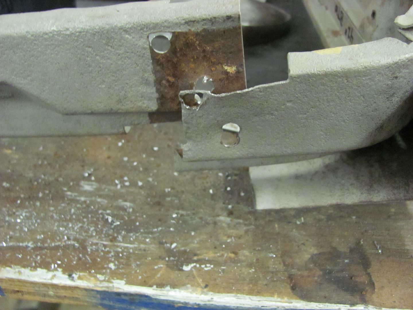
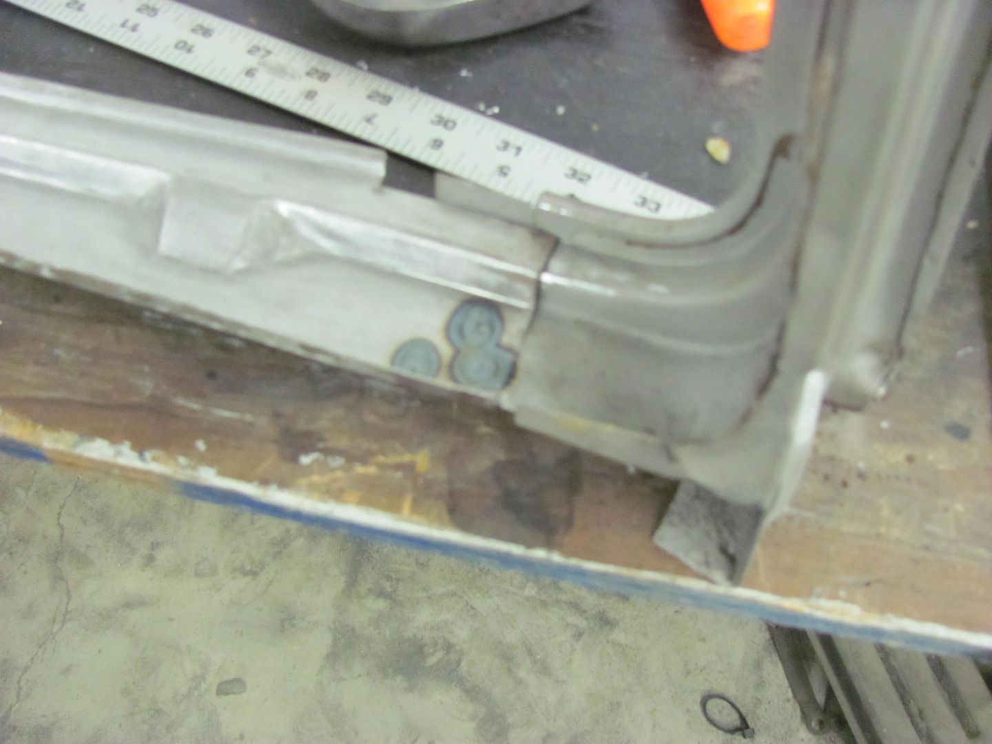
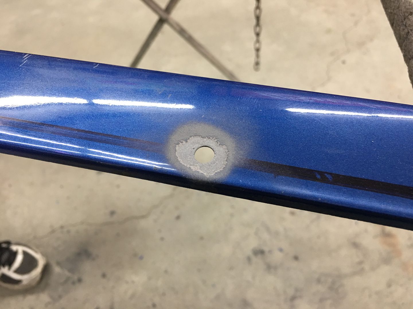
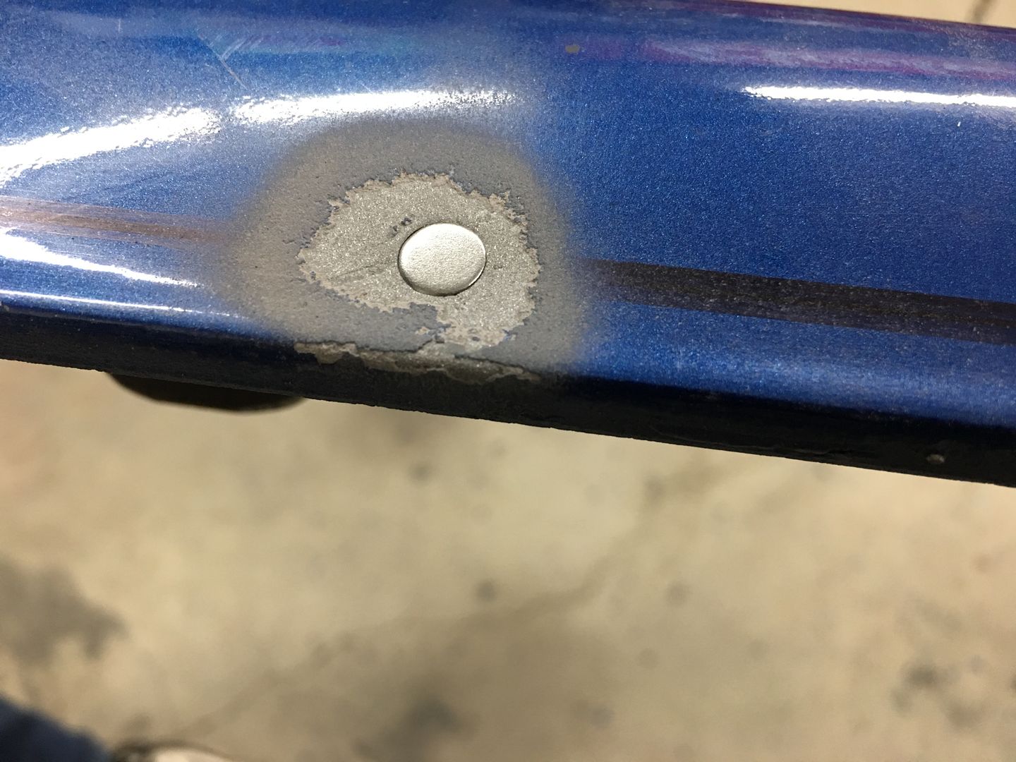
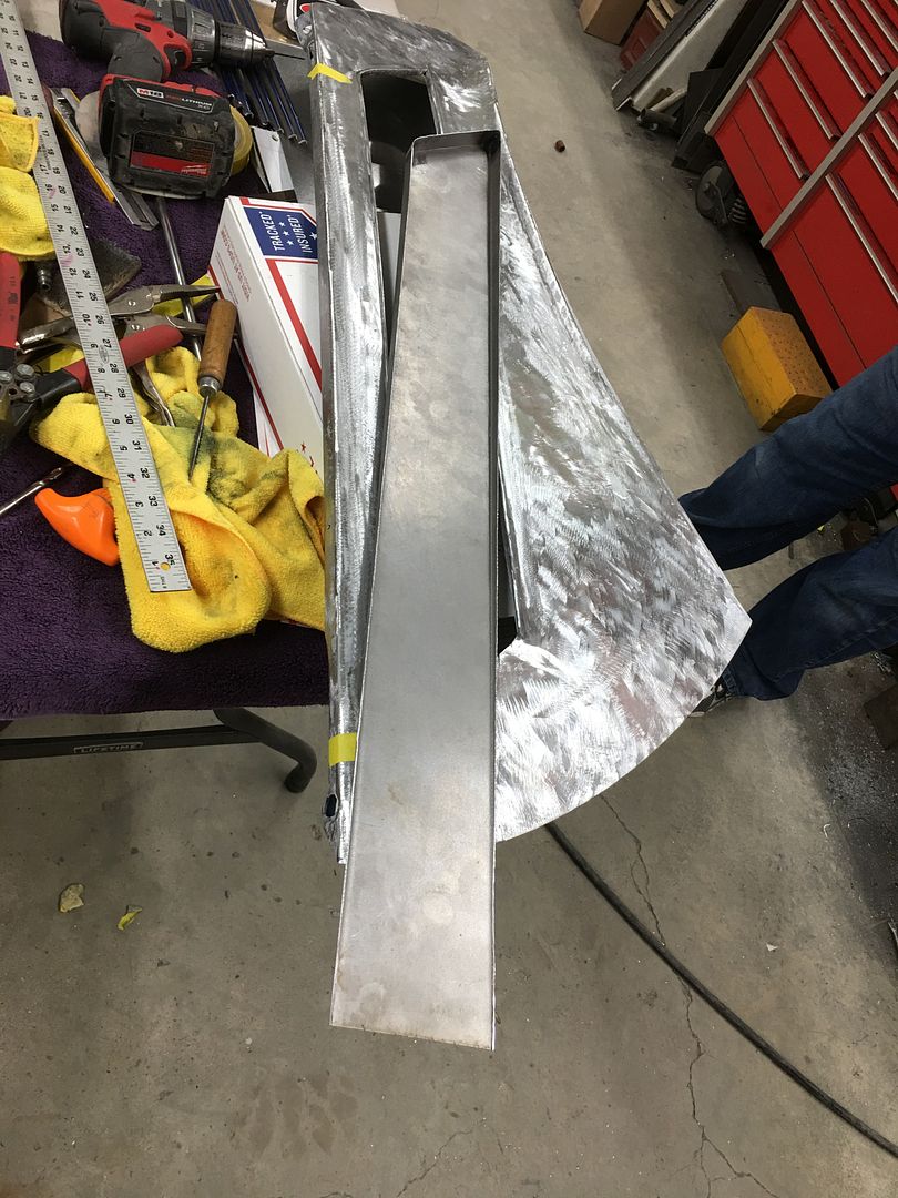
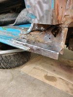
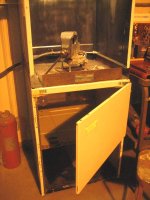
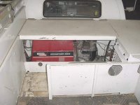
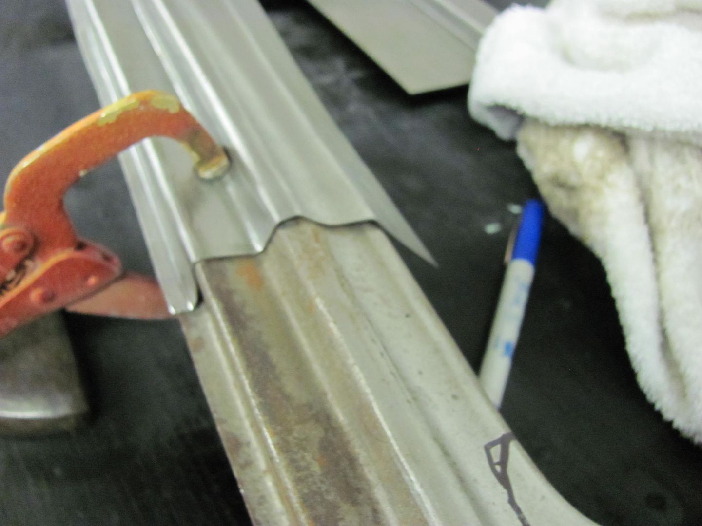
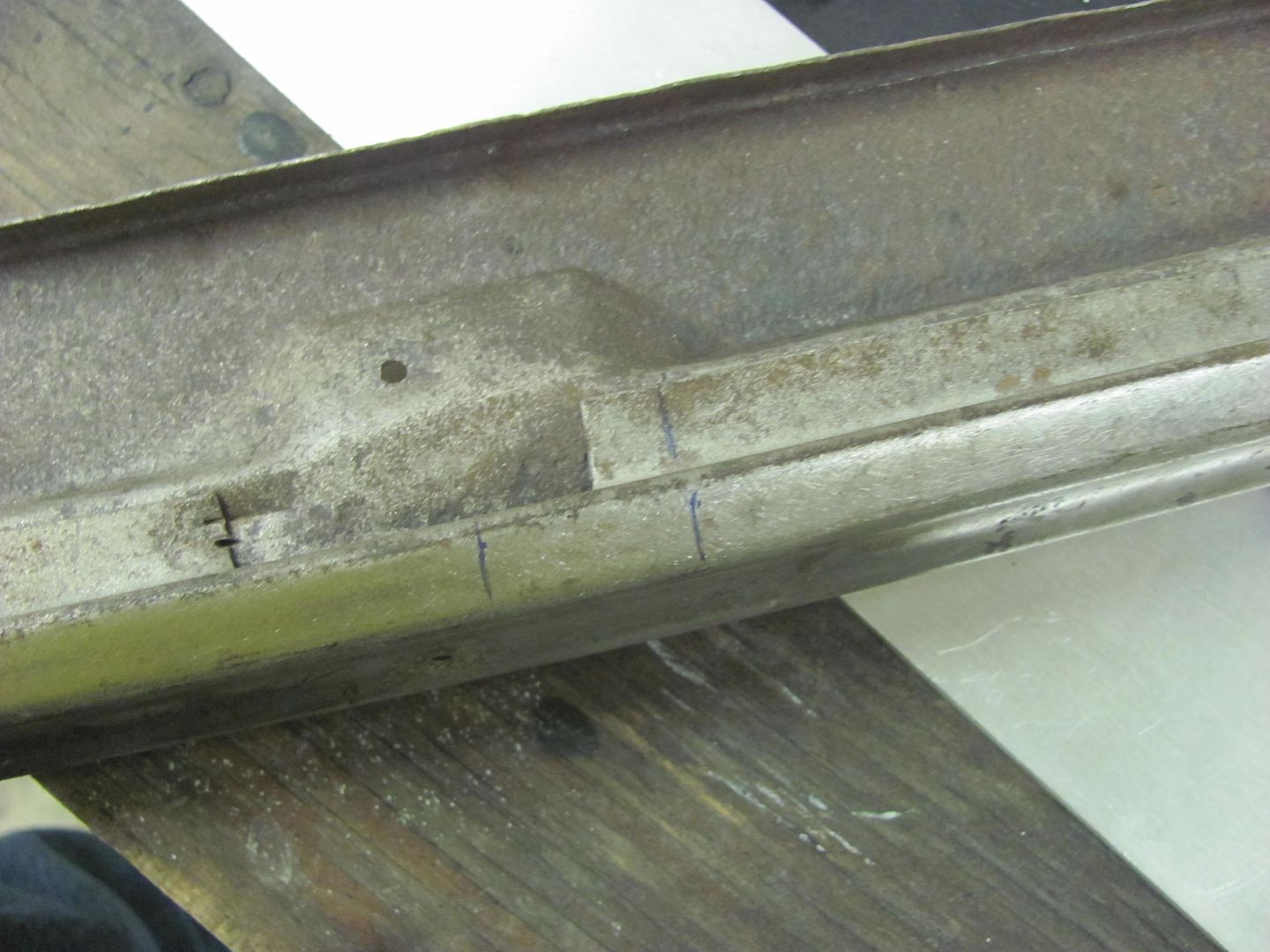
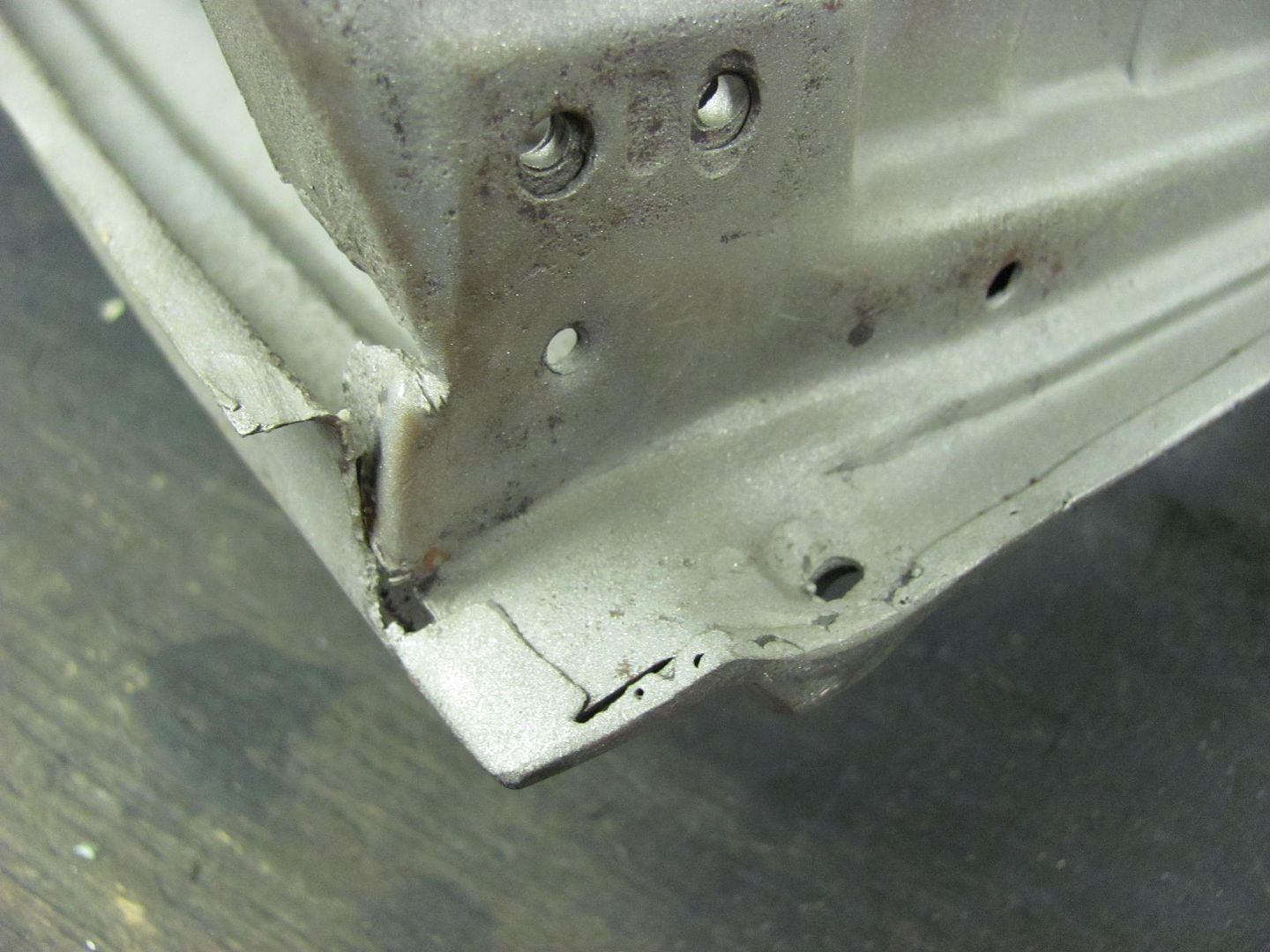
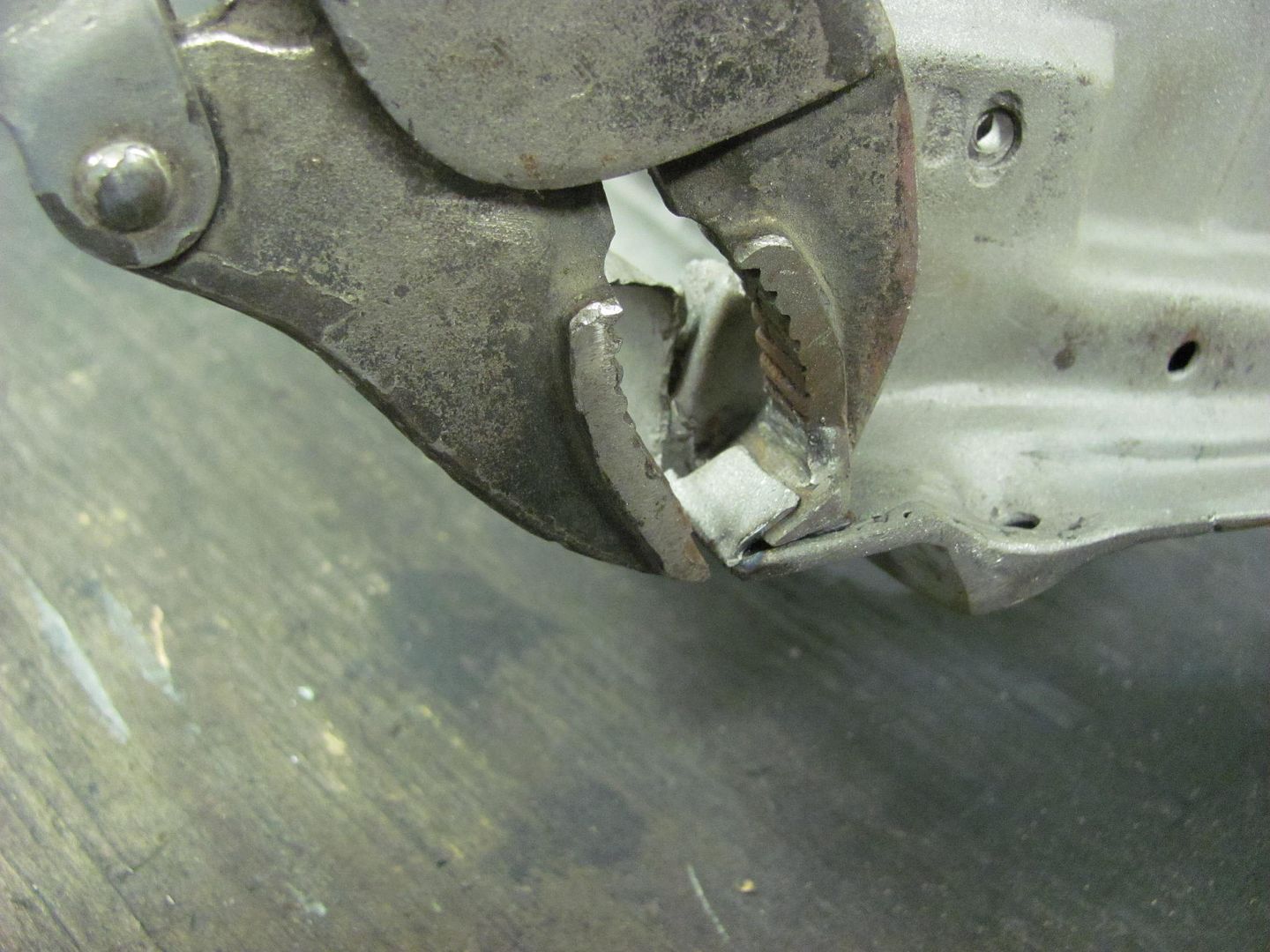
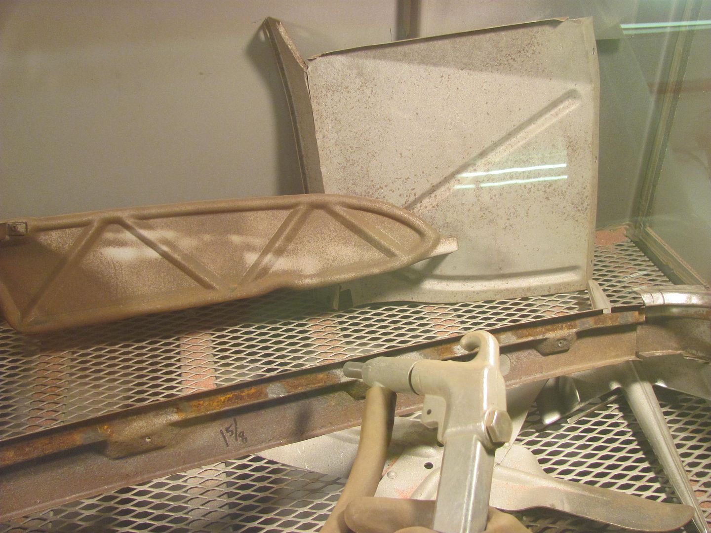
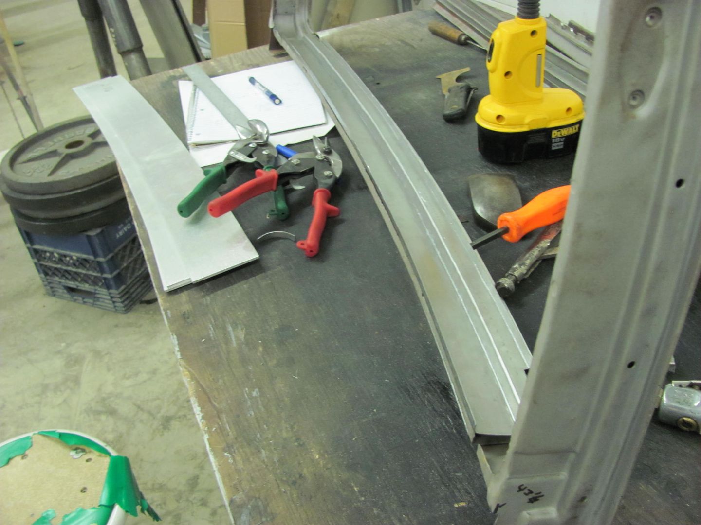
So today I got a phone call, and long story short, needed to do some metalshaping for a Caterpillar D5 dozer. No, really! The last time this same mishap occurred was over ten years ago in my back yard. It seems dirt/mud gets packed between the stump pan and the oil pan, until a hole rusts through the oil pan. Last time Paul bought a new oil pan, but it sounded like he needed to use the dozer this week, so he brought it over for repair..


Picture232.jpg


Picture234.jpg


Picture235.jpg


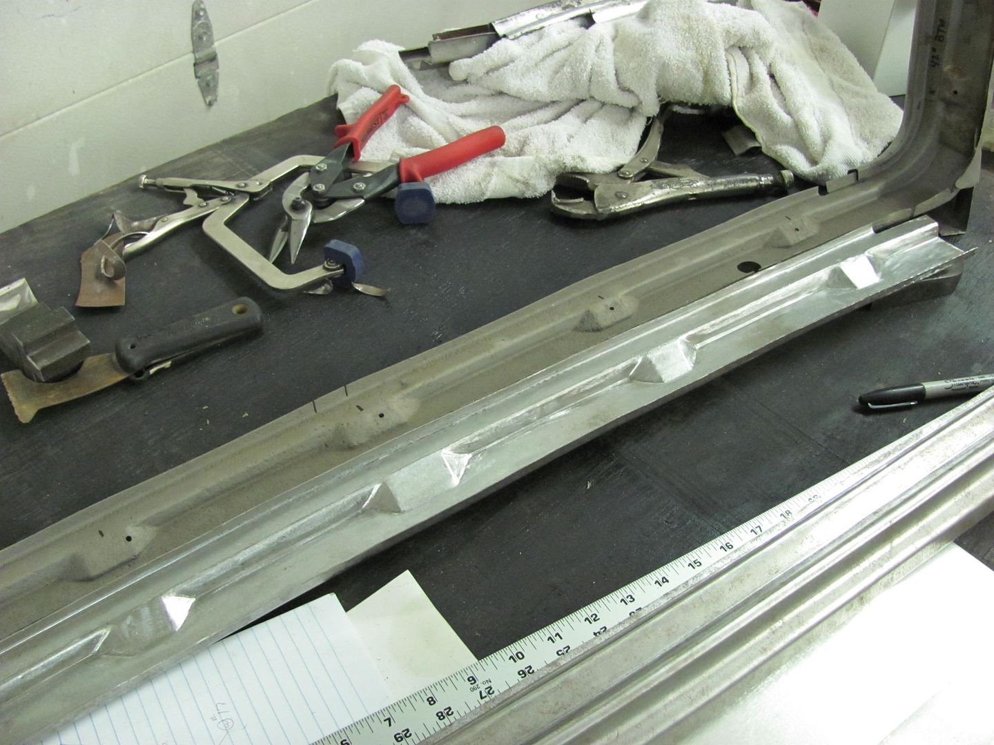
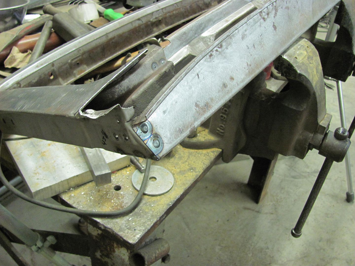
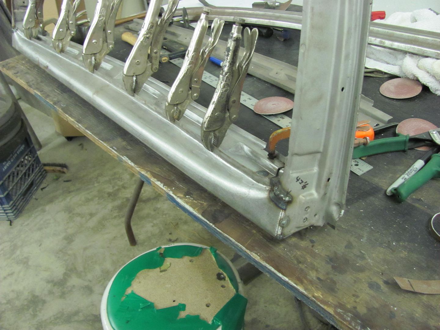
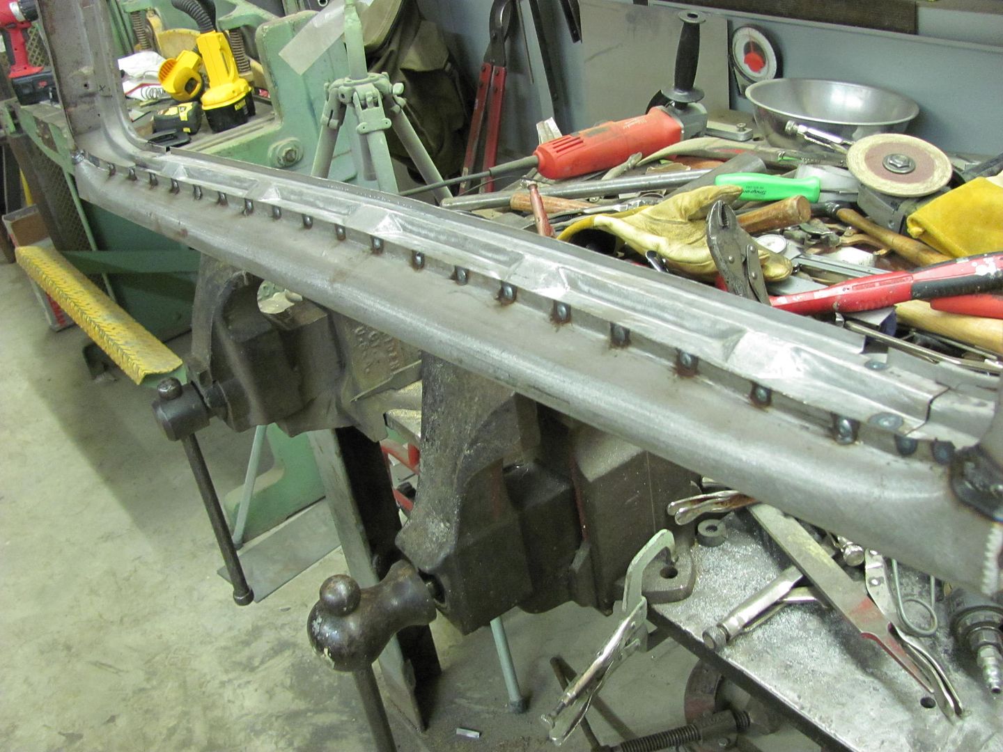
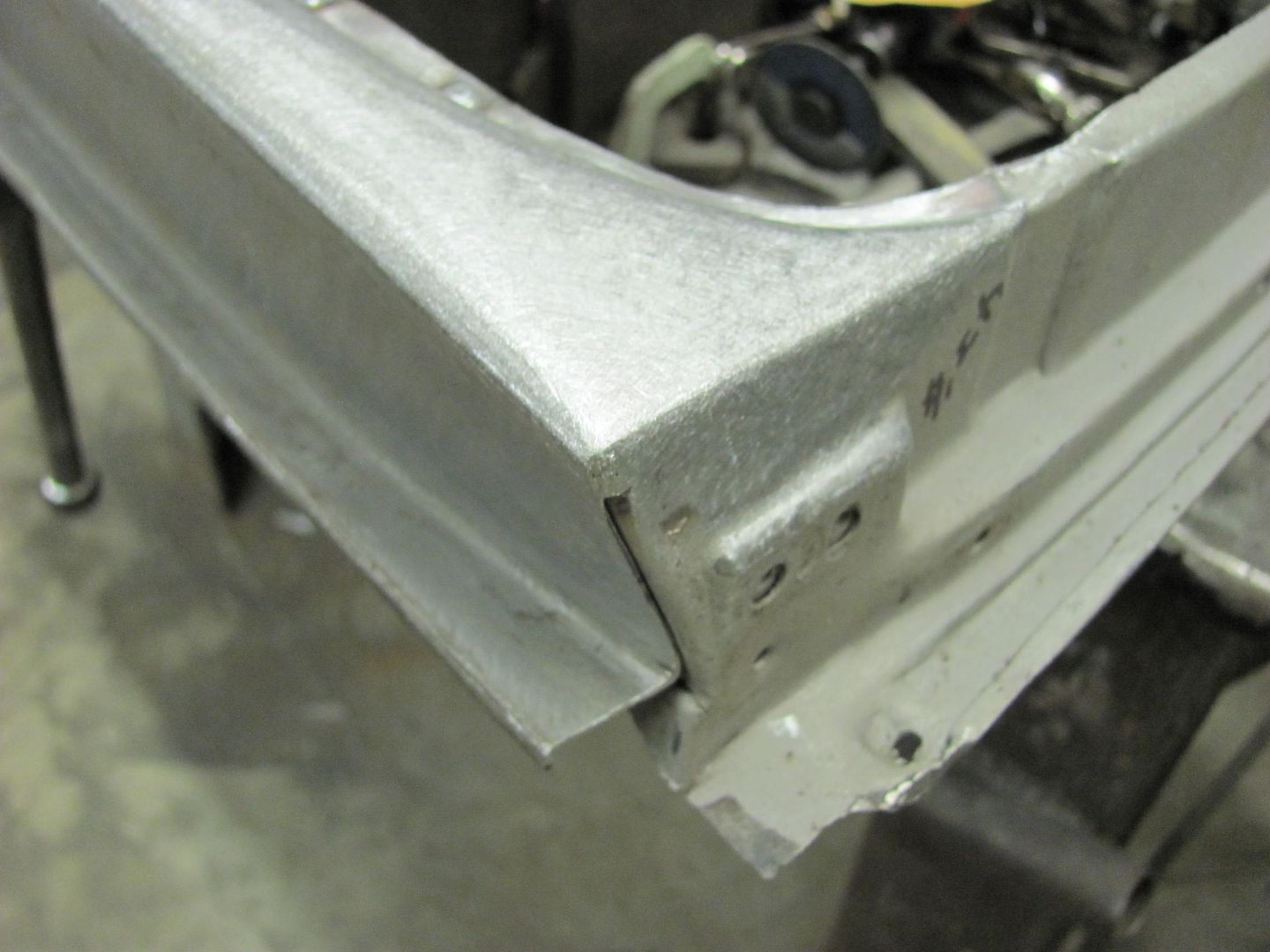
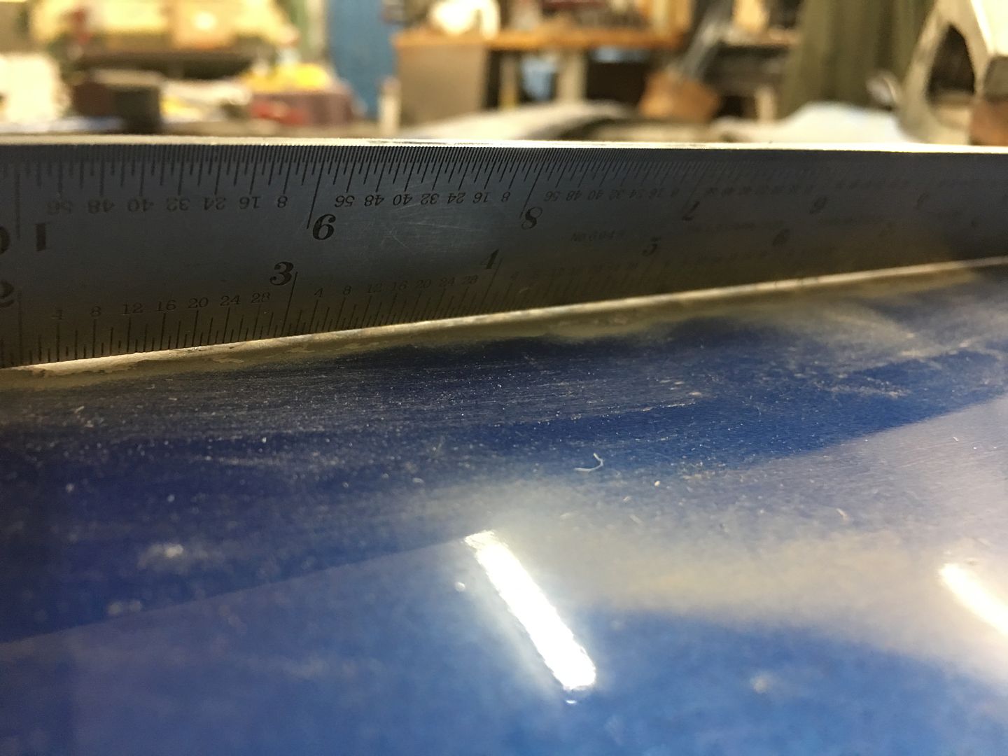
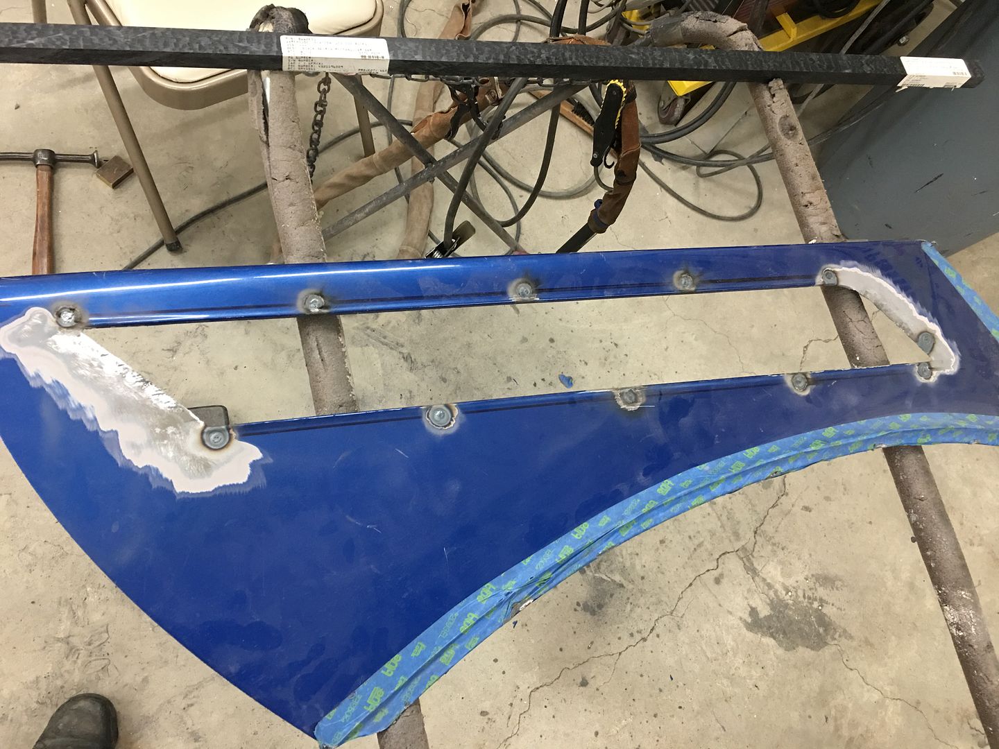
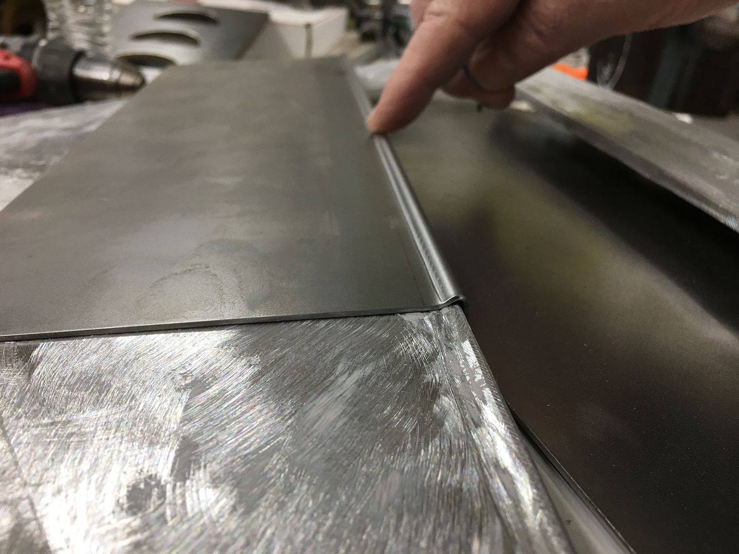
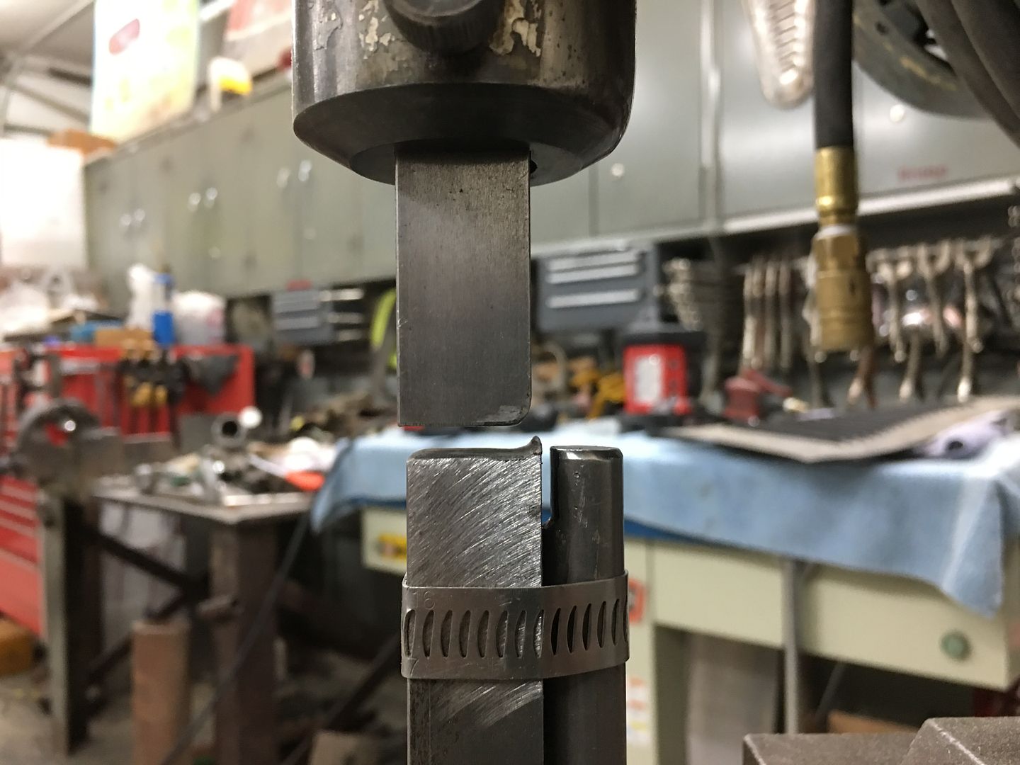
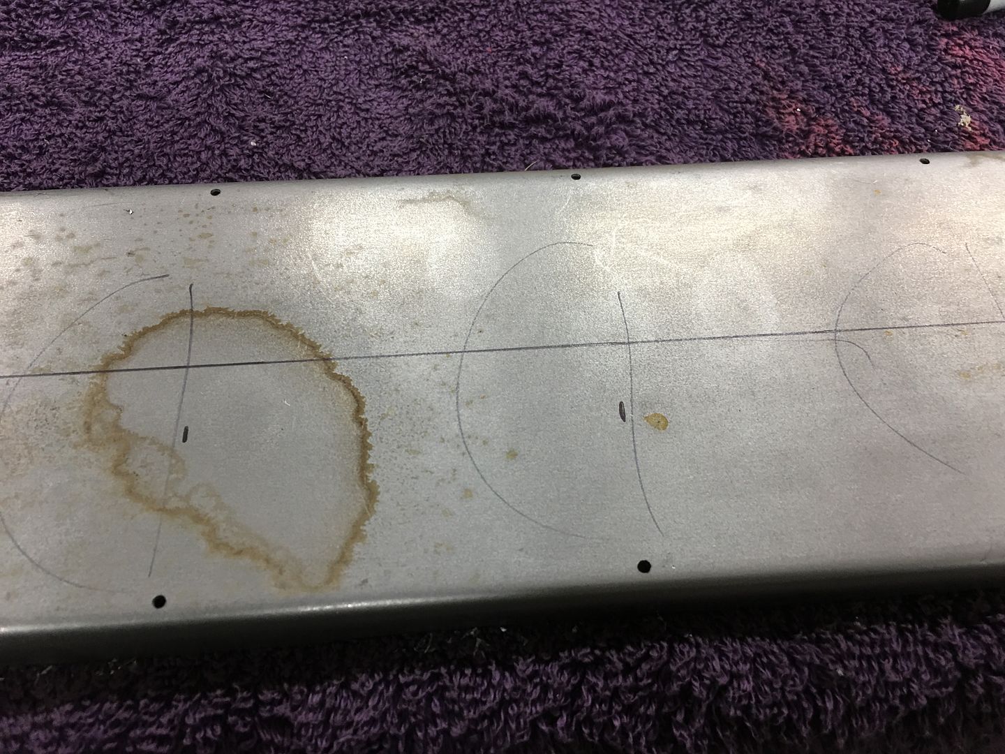
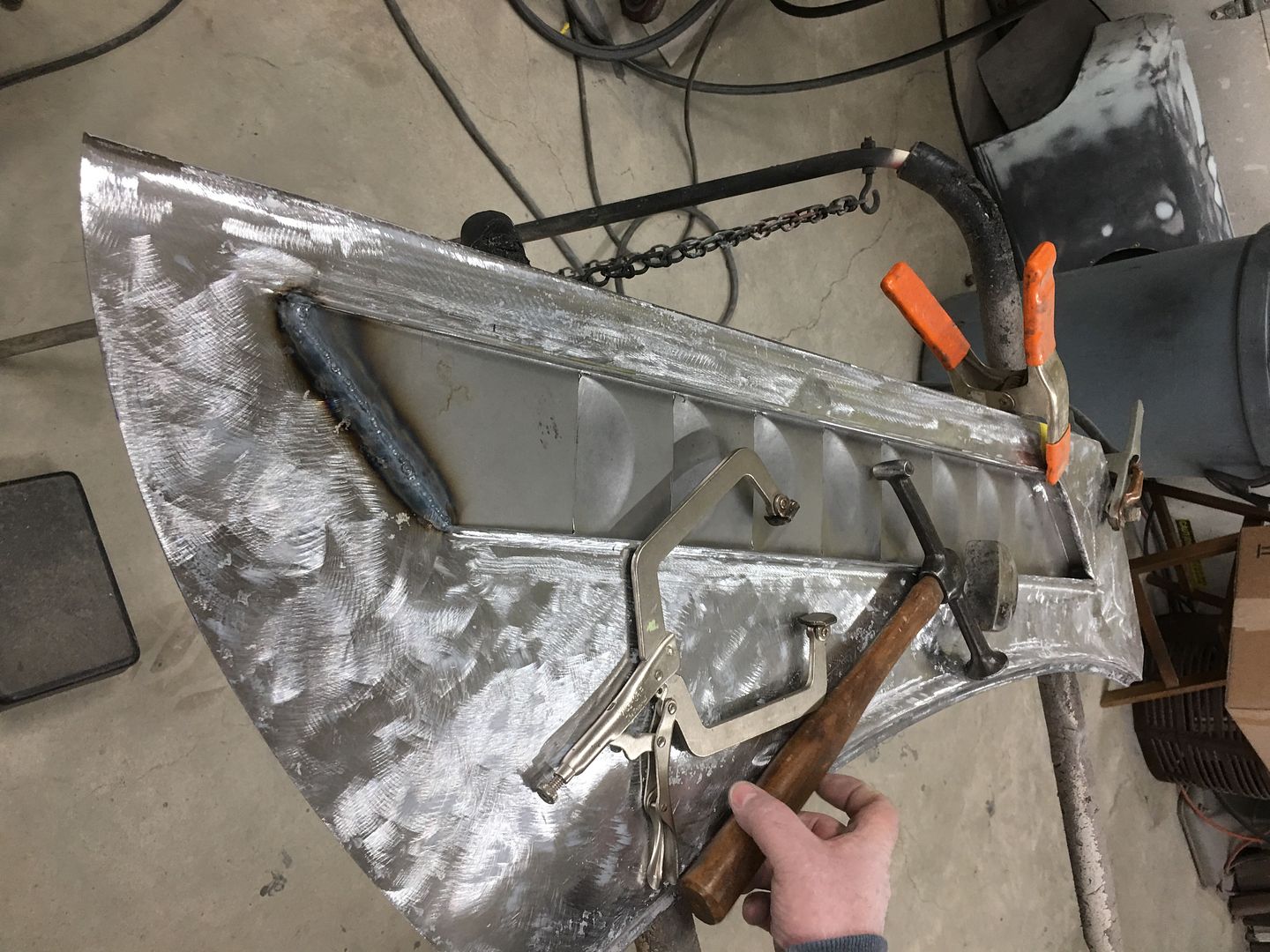
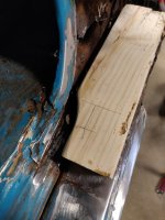
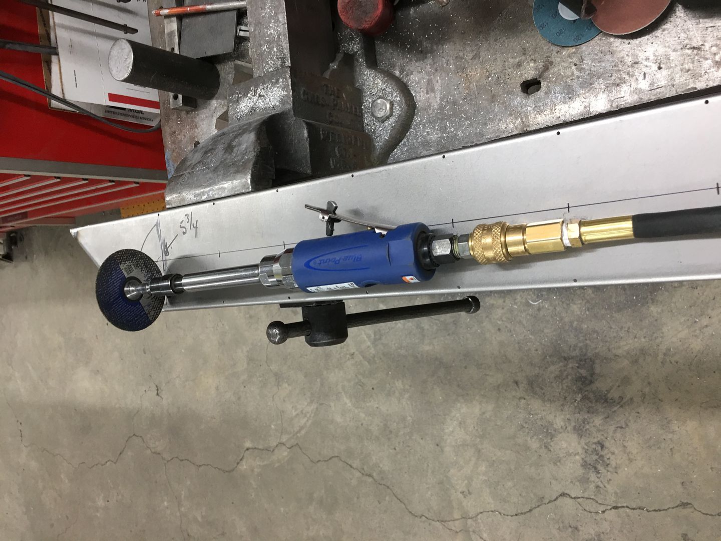
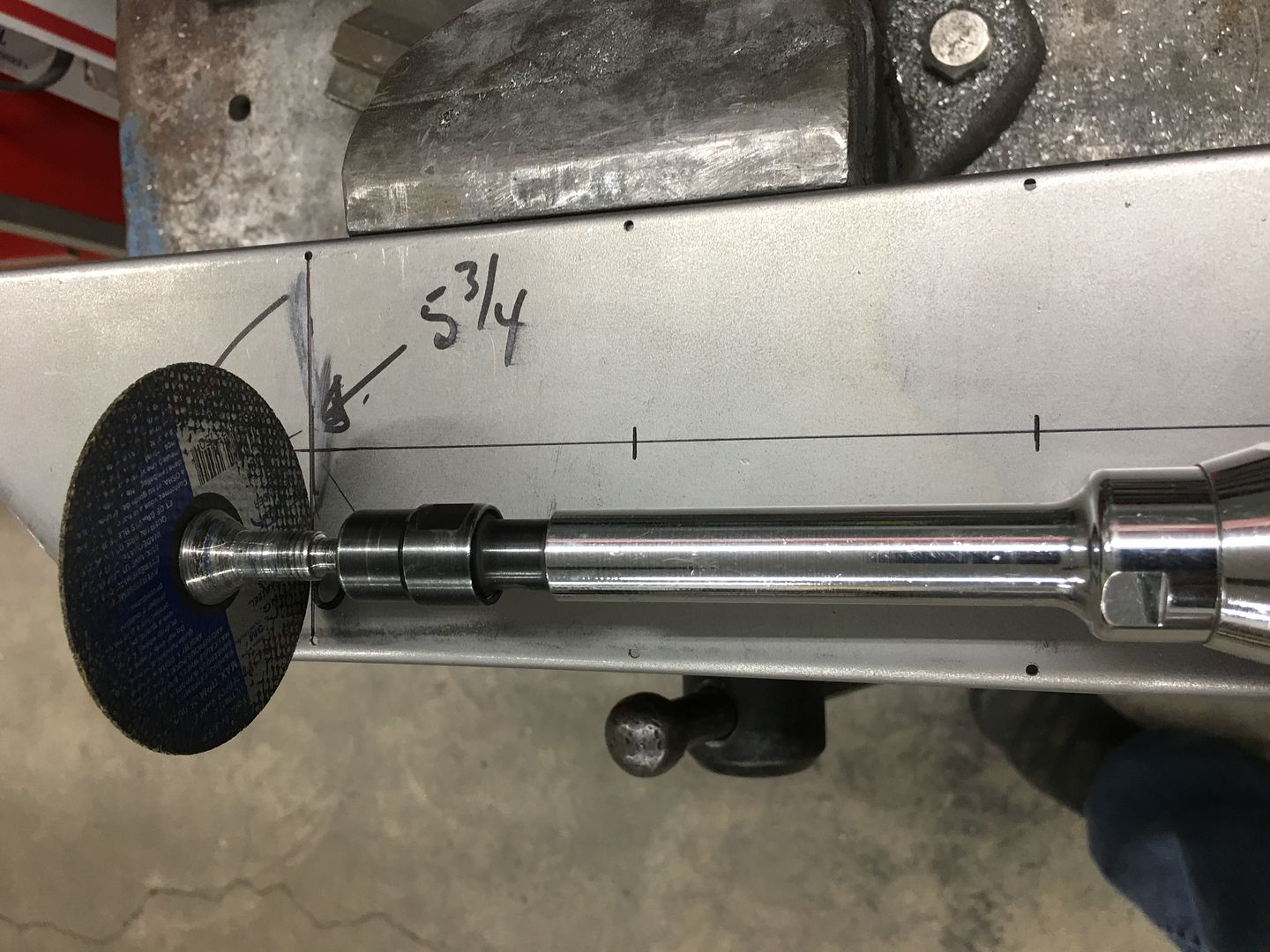
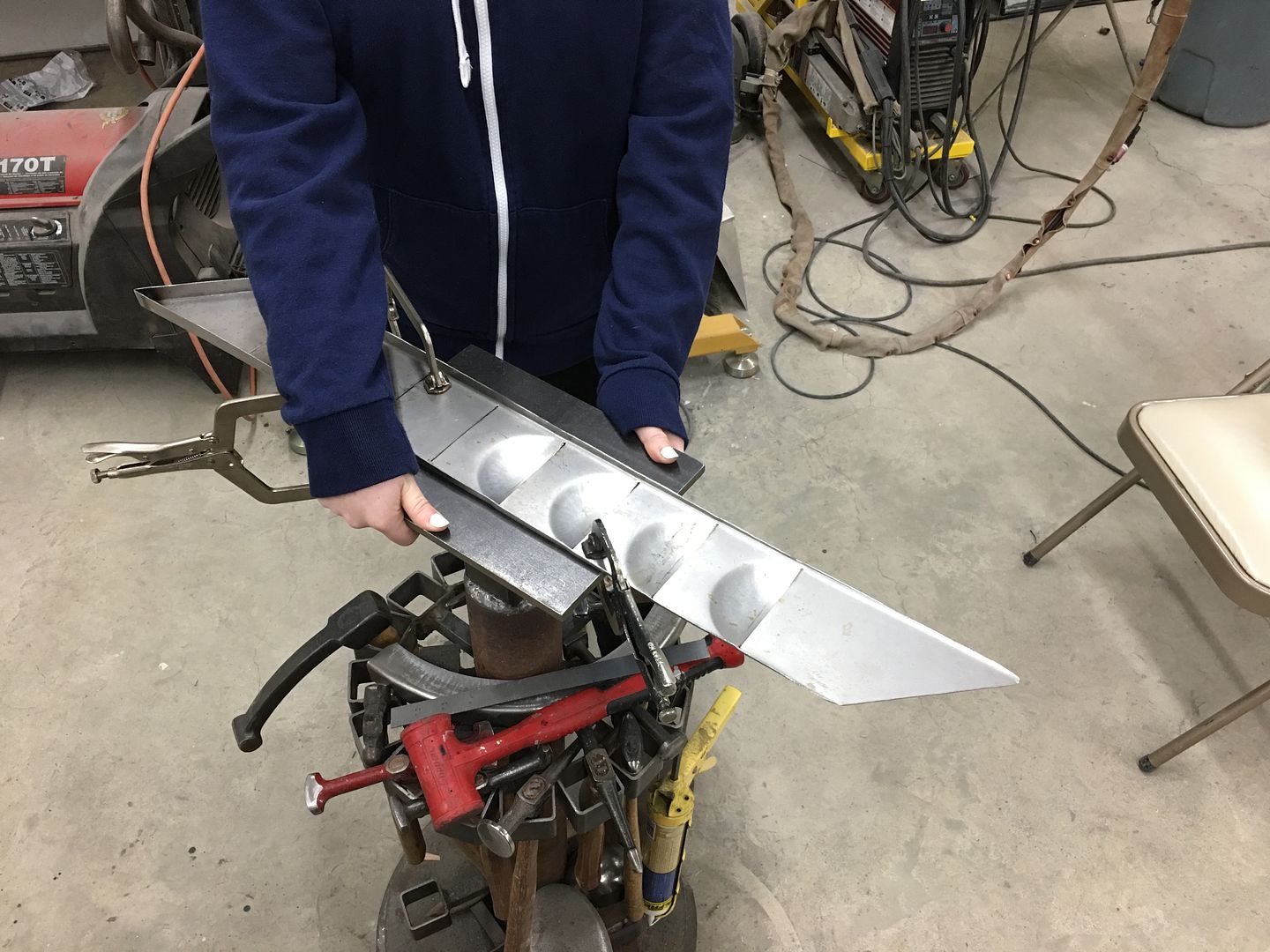
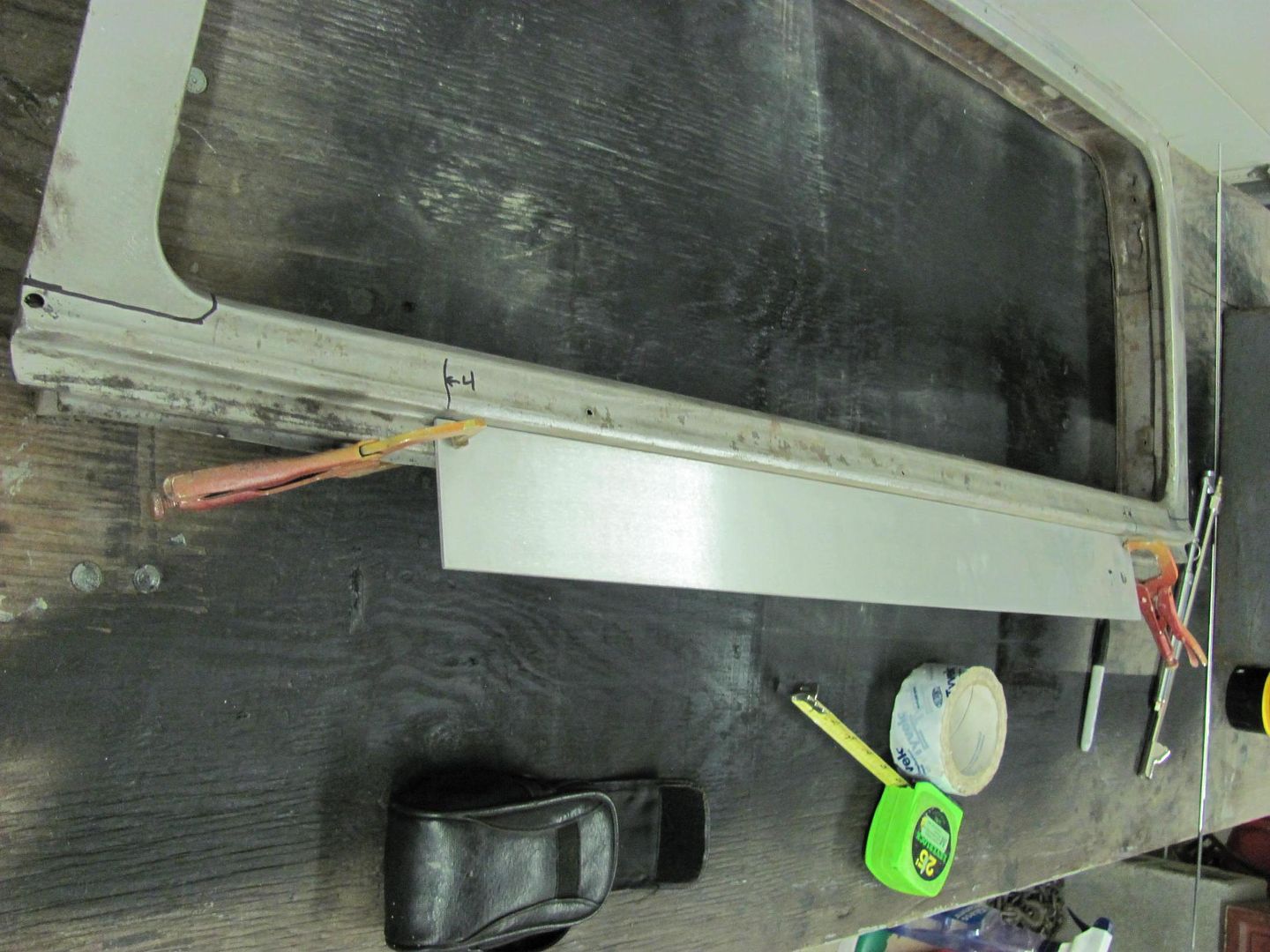
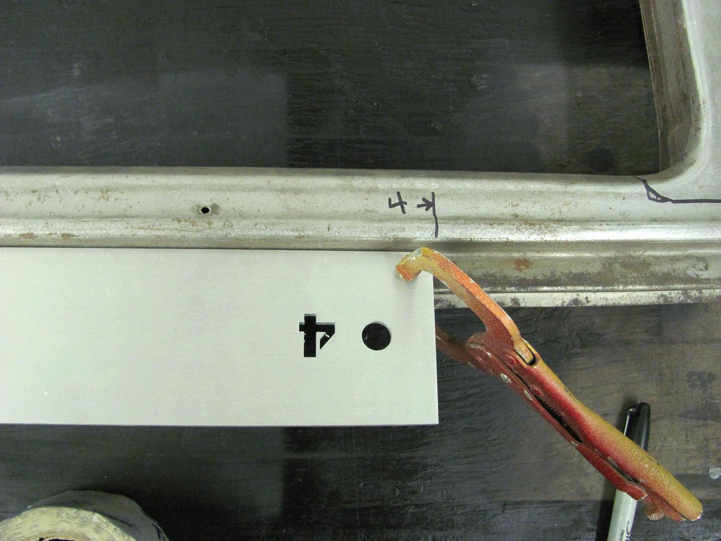
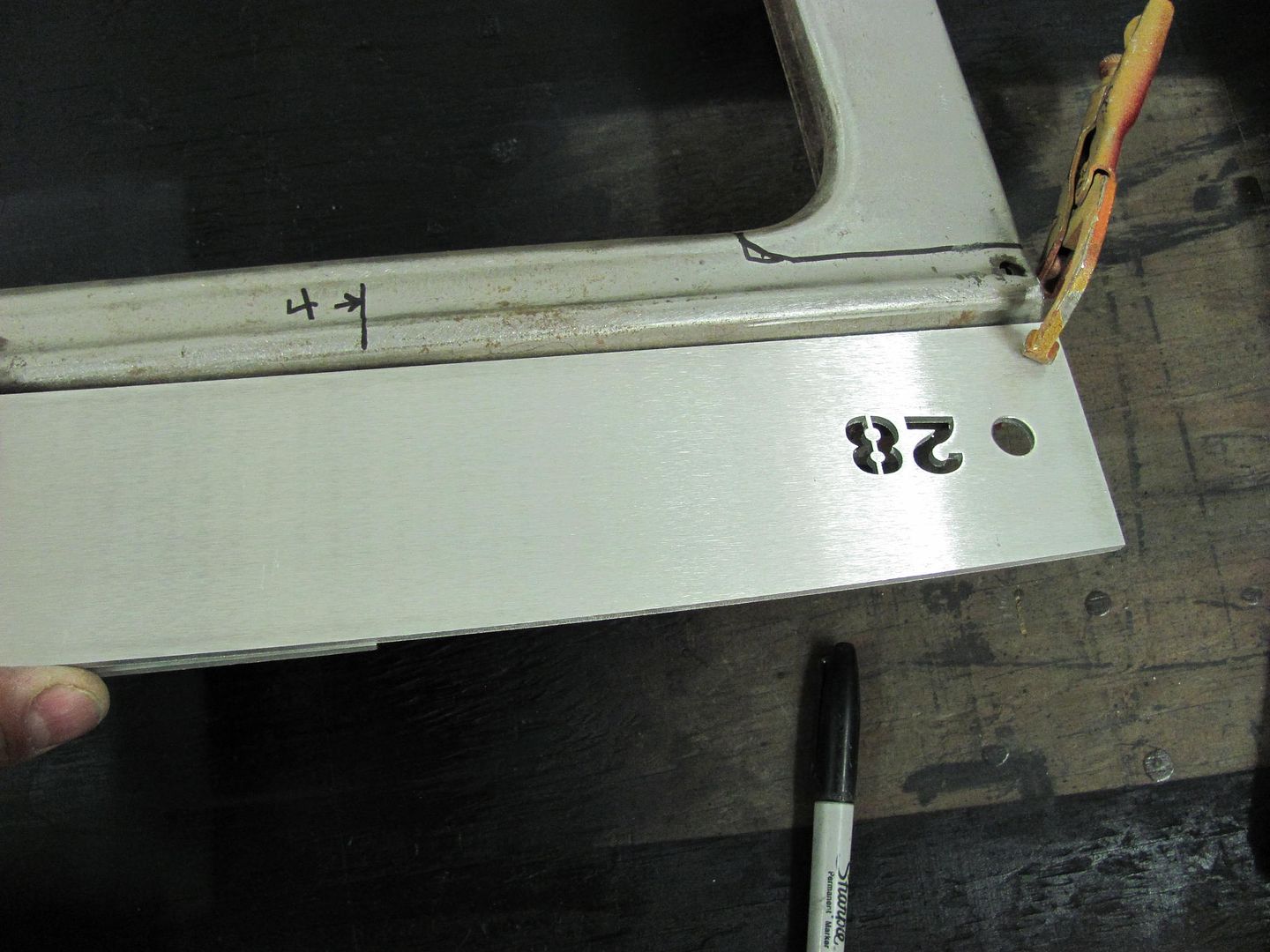
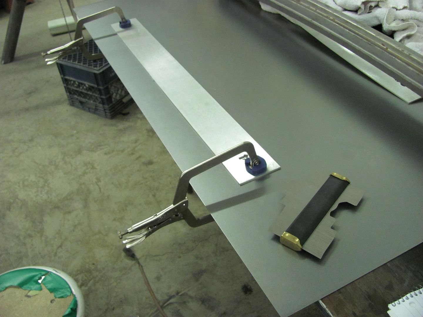
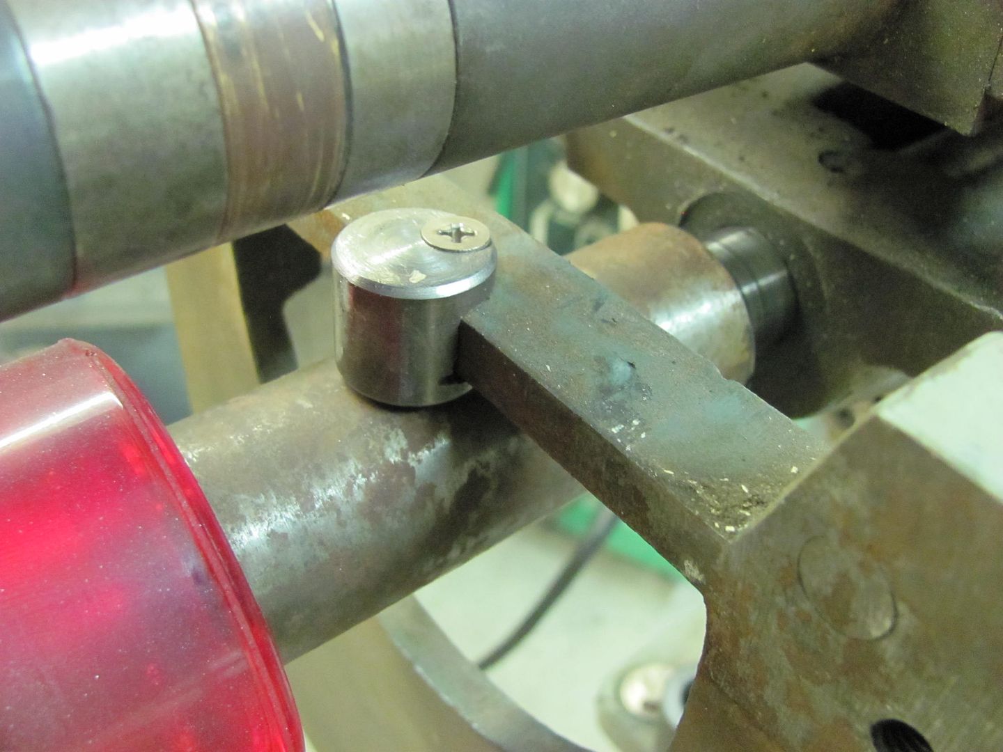
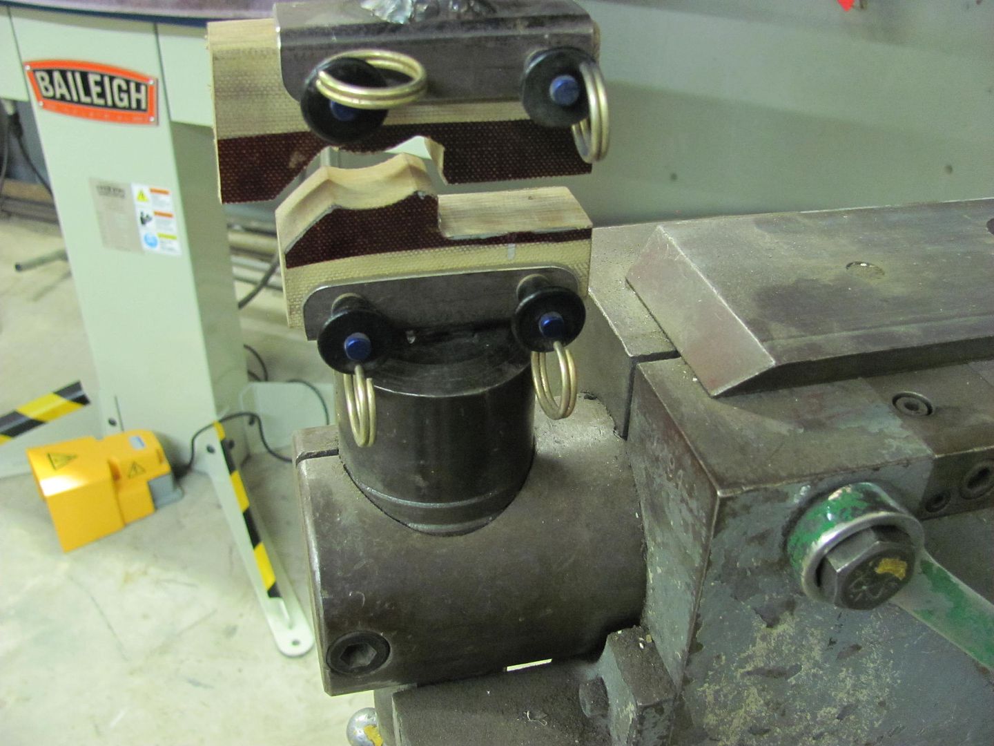
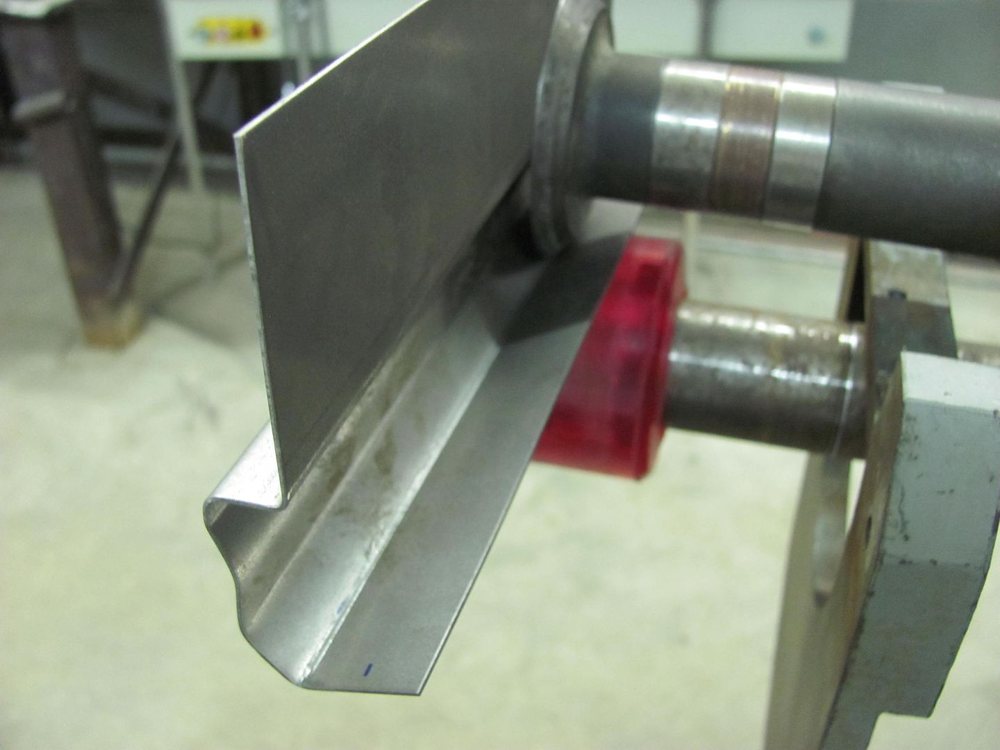
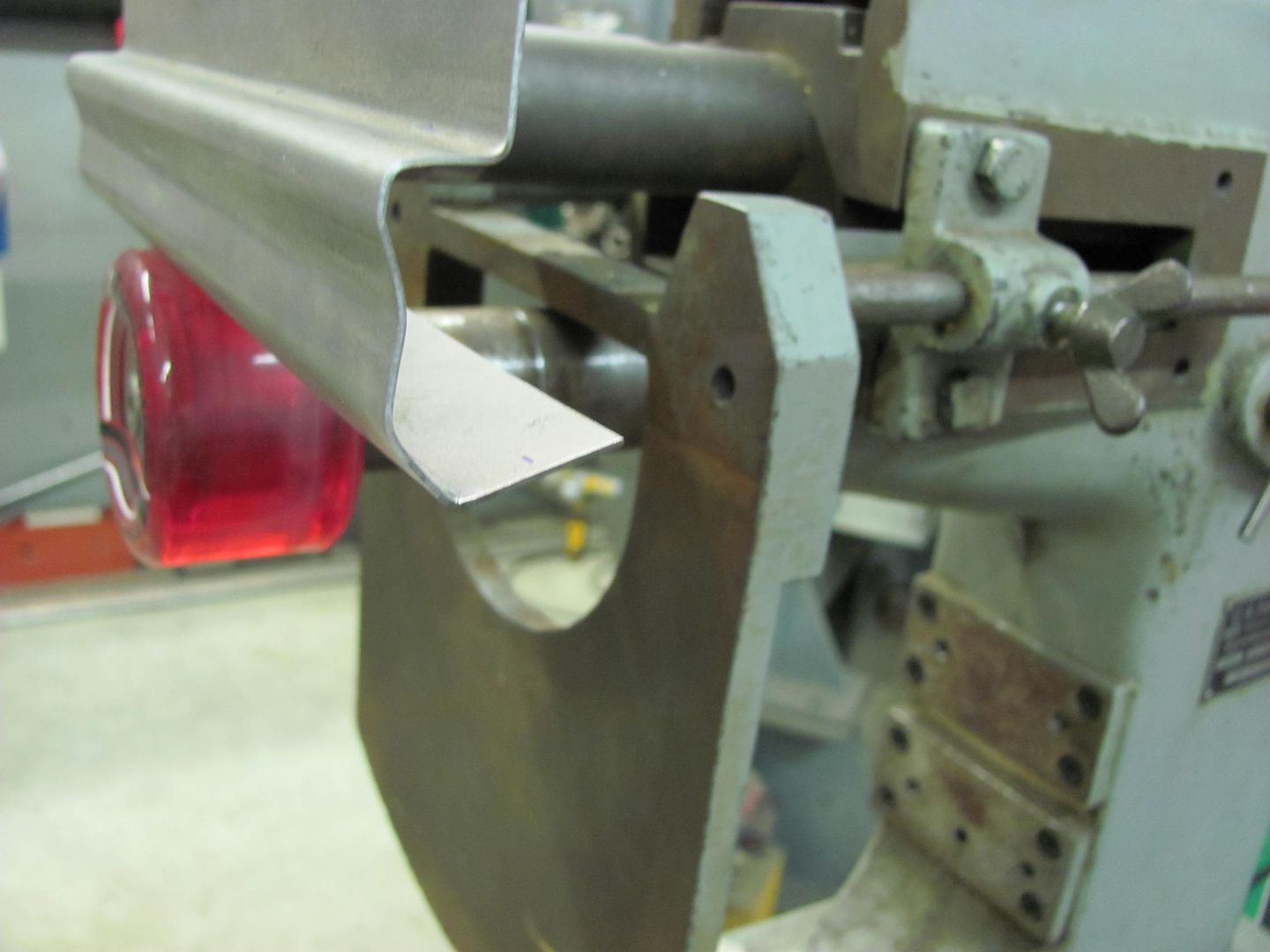
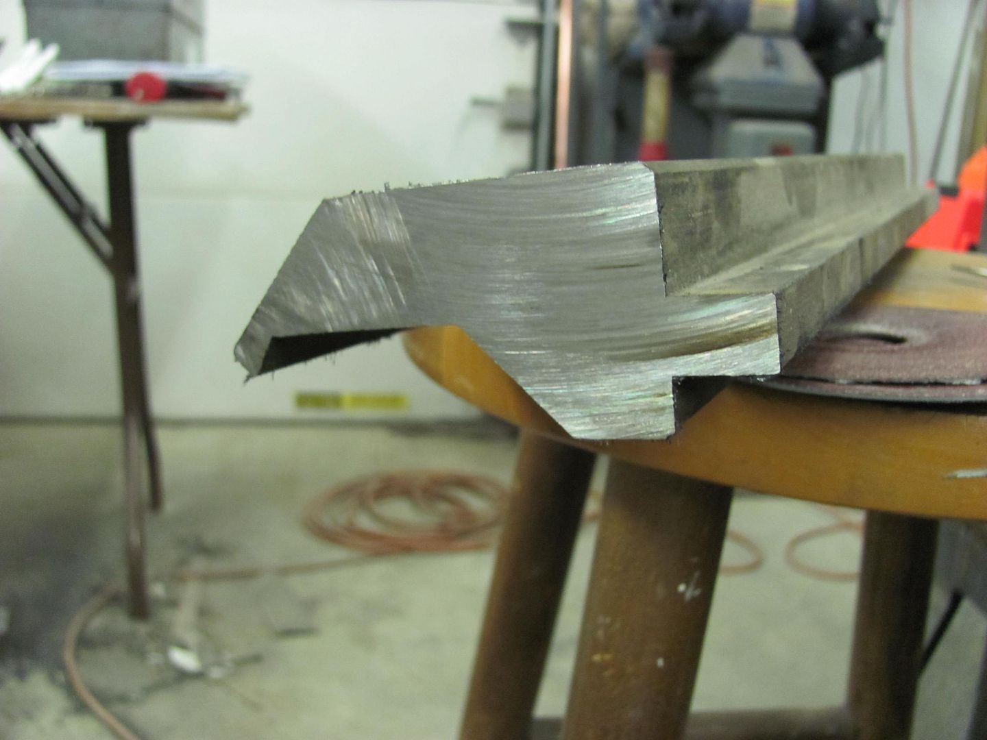
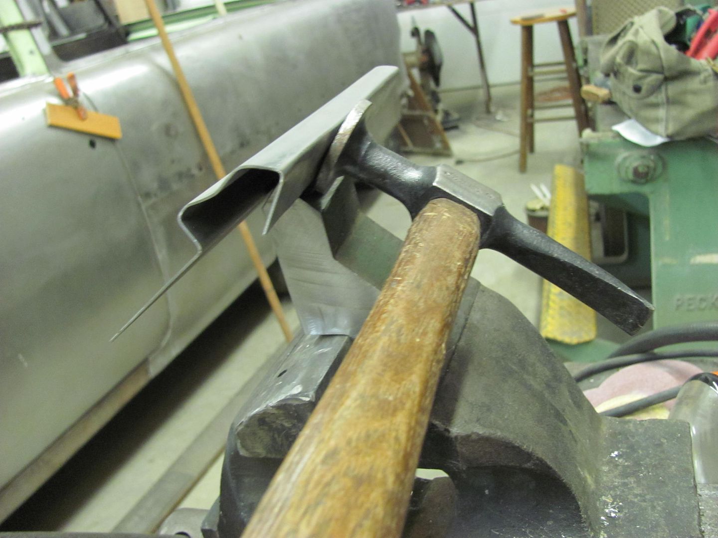
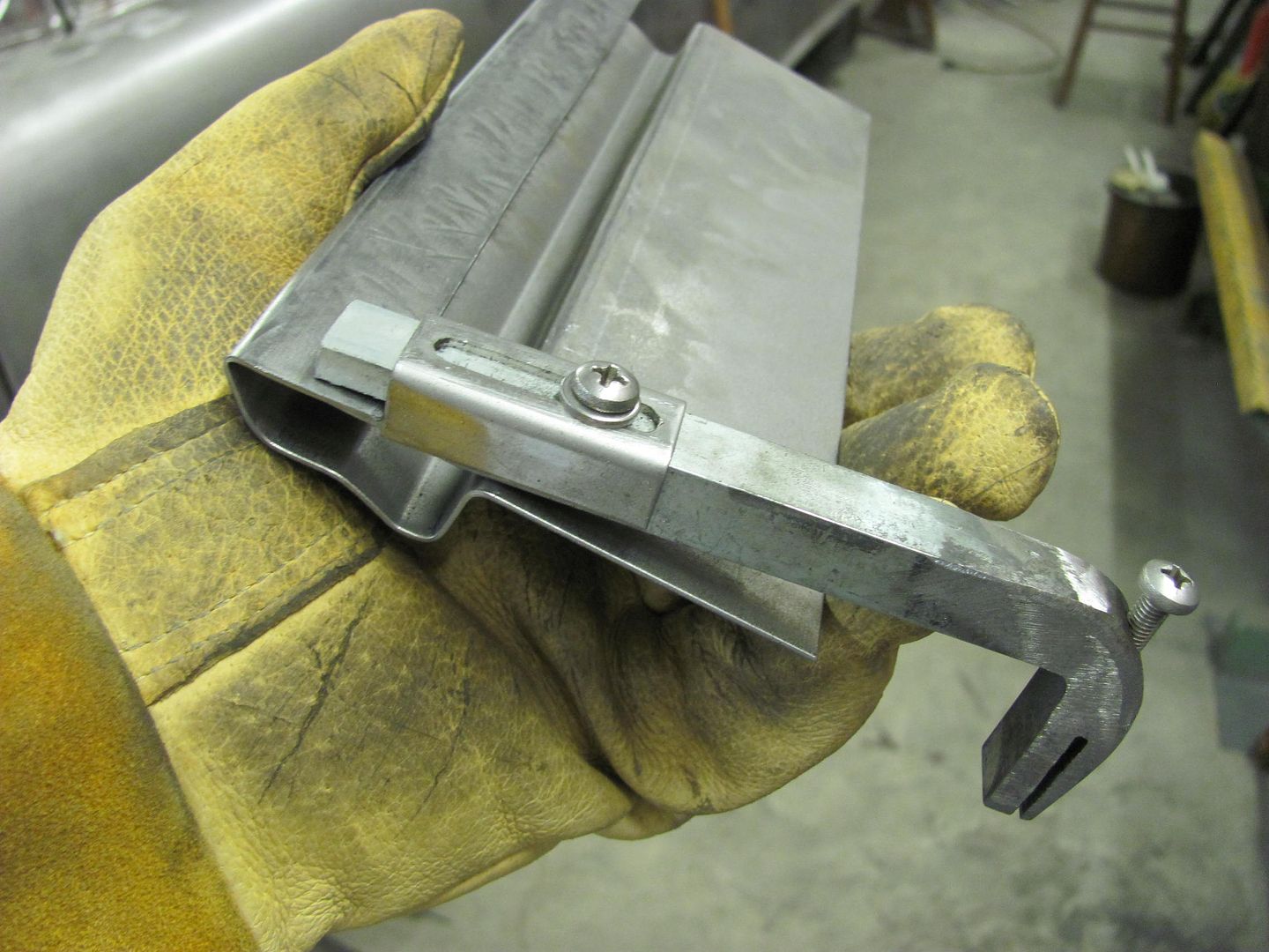
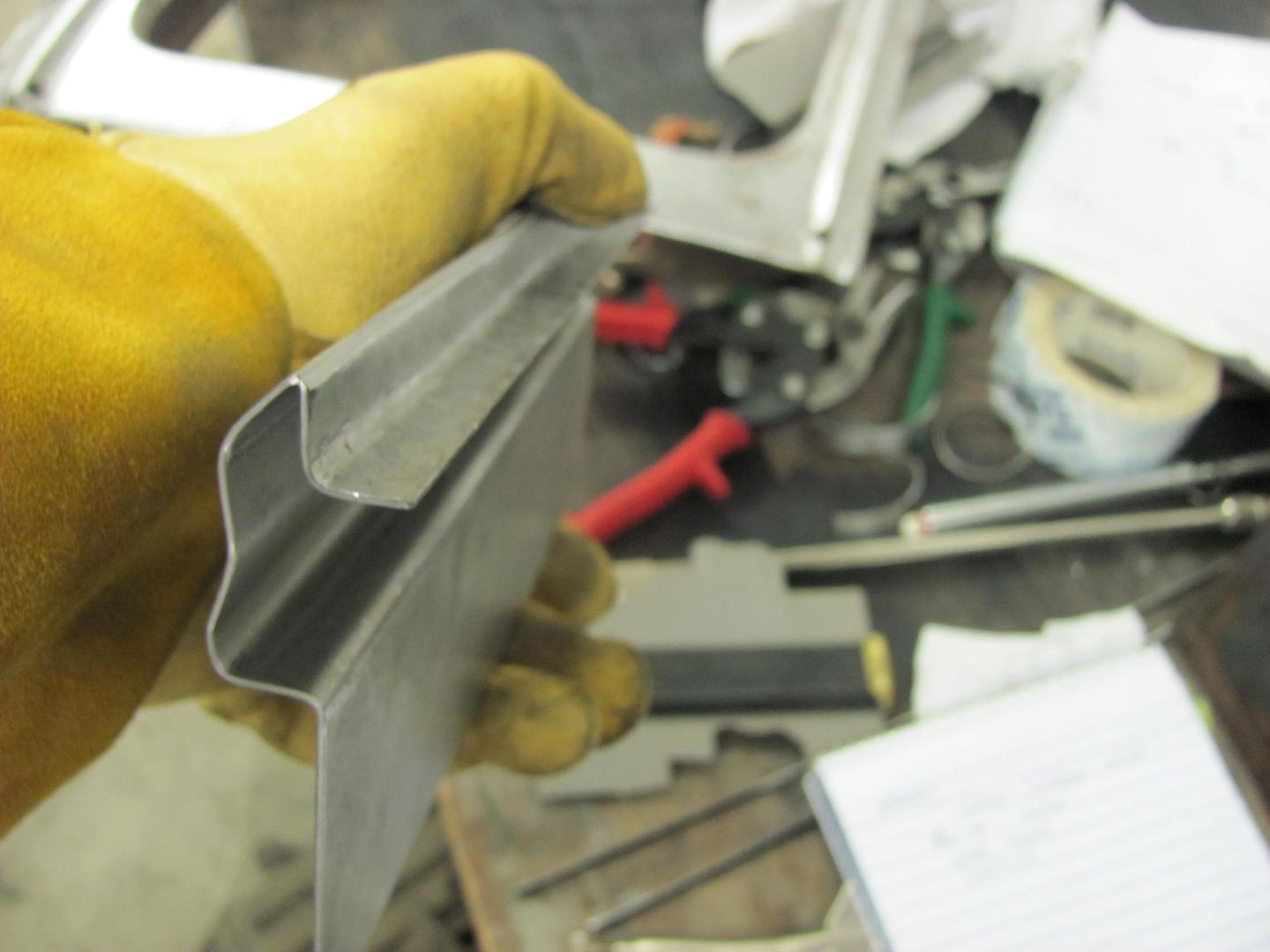
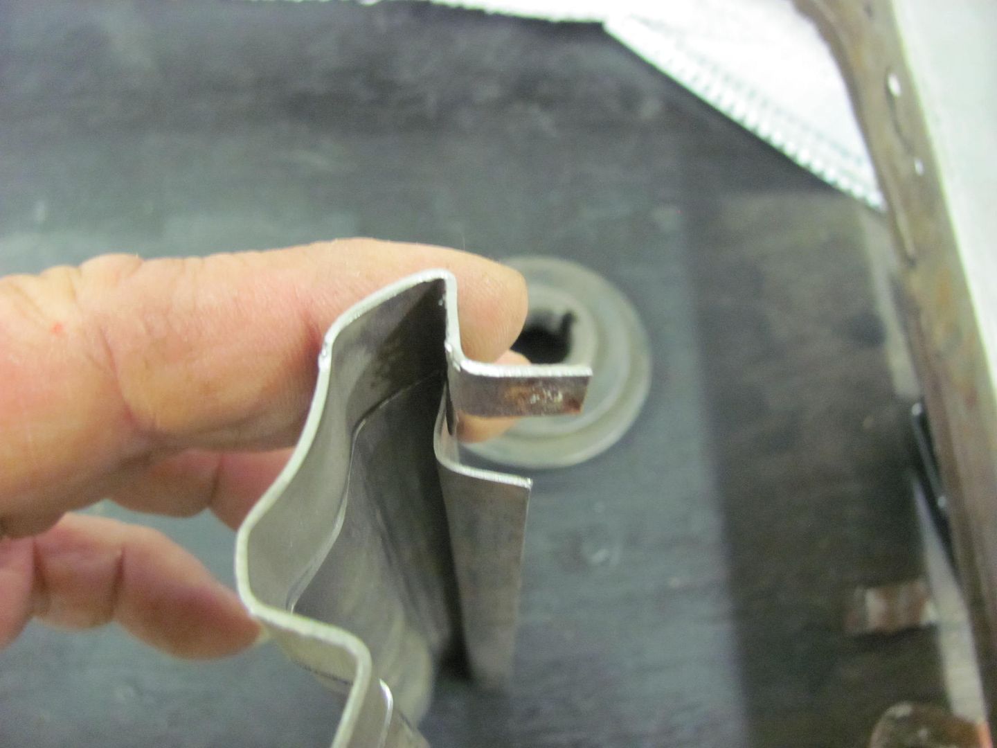
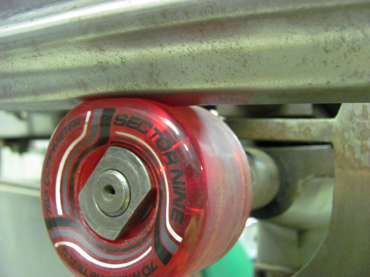
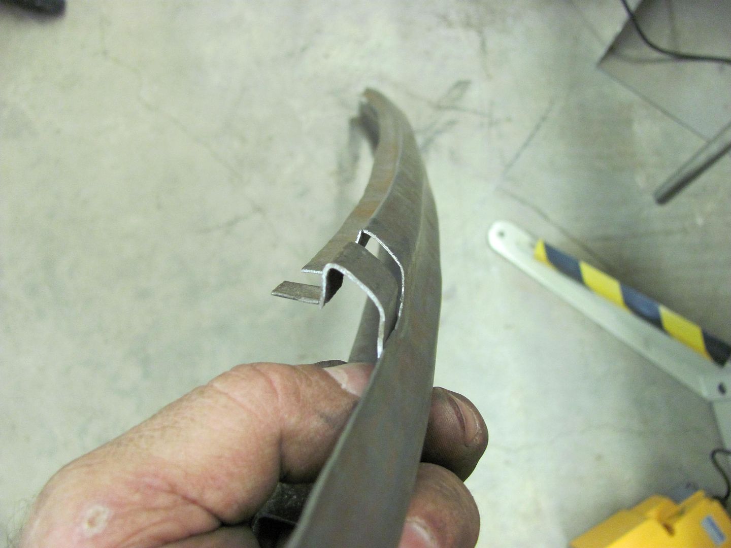
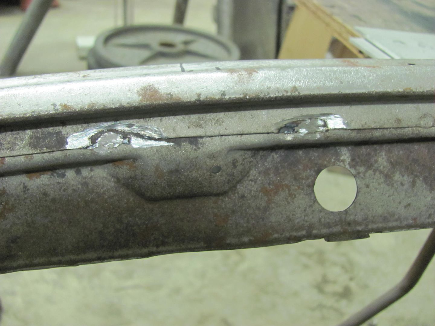
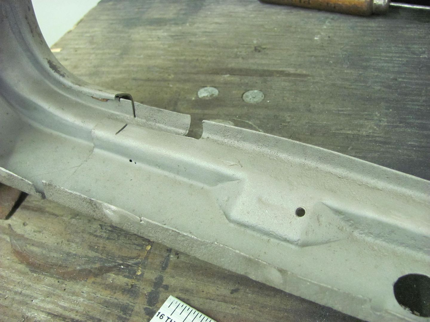
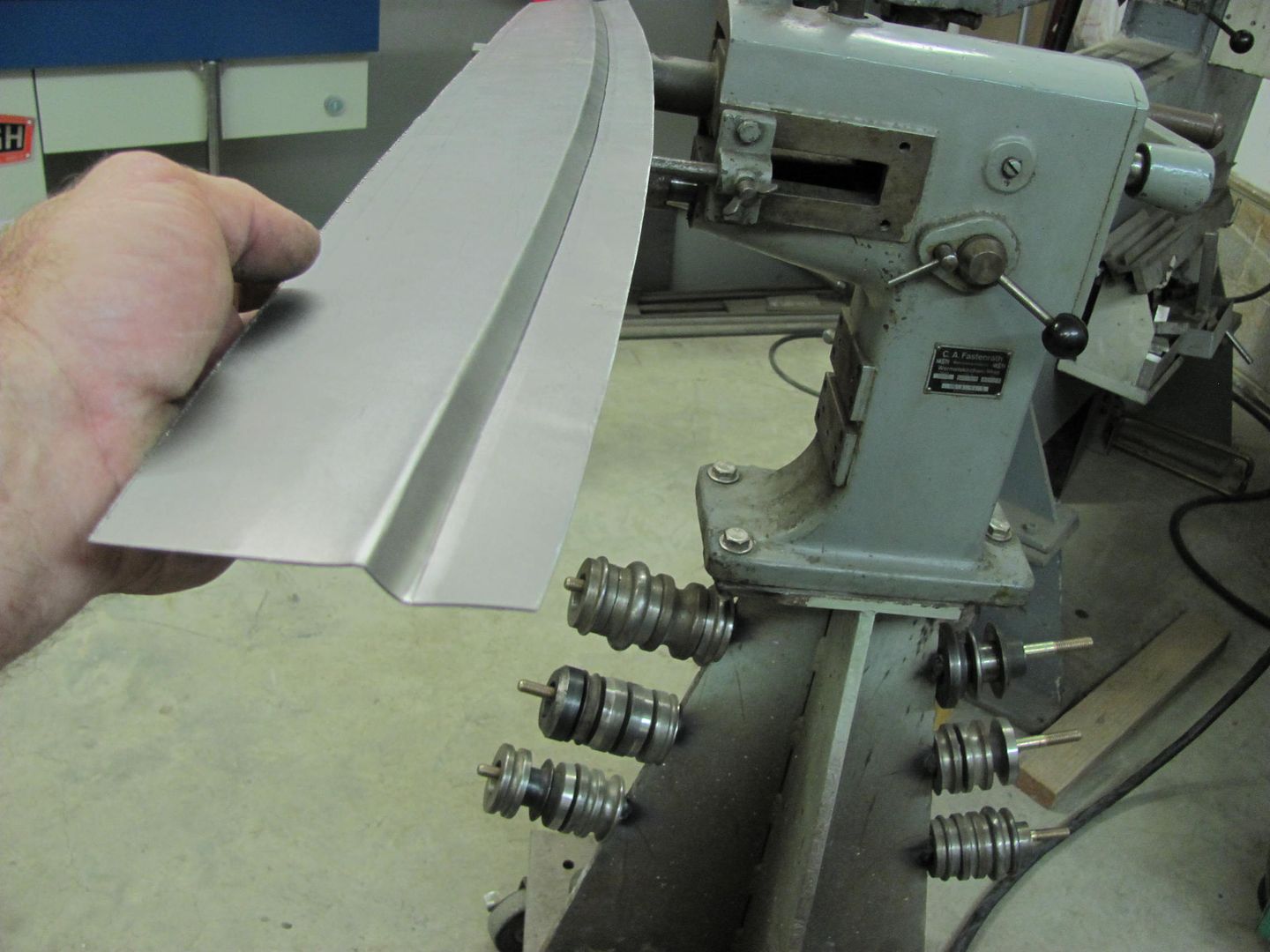
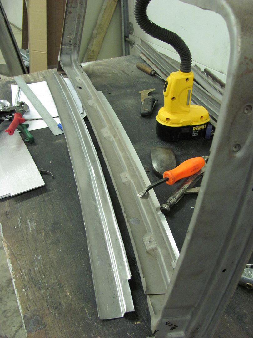
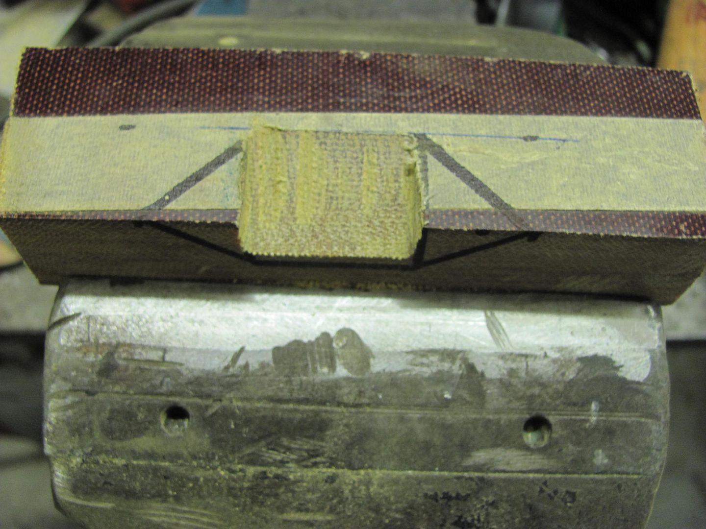
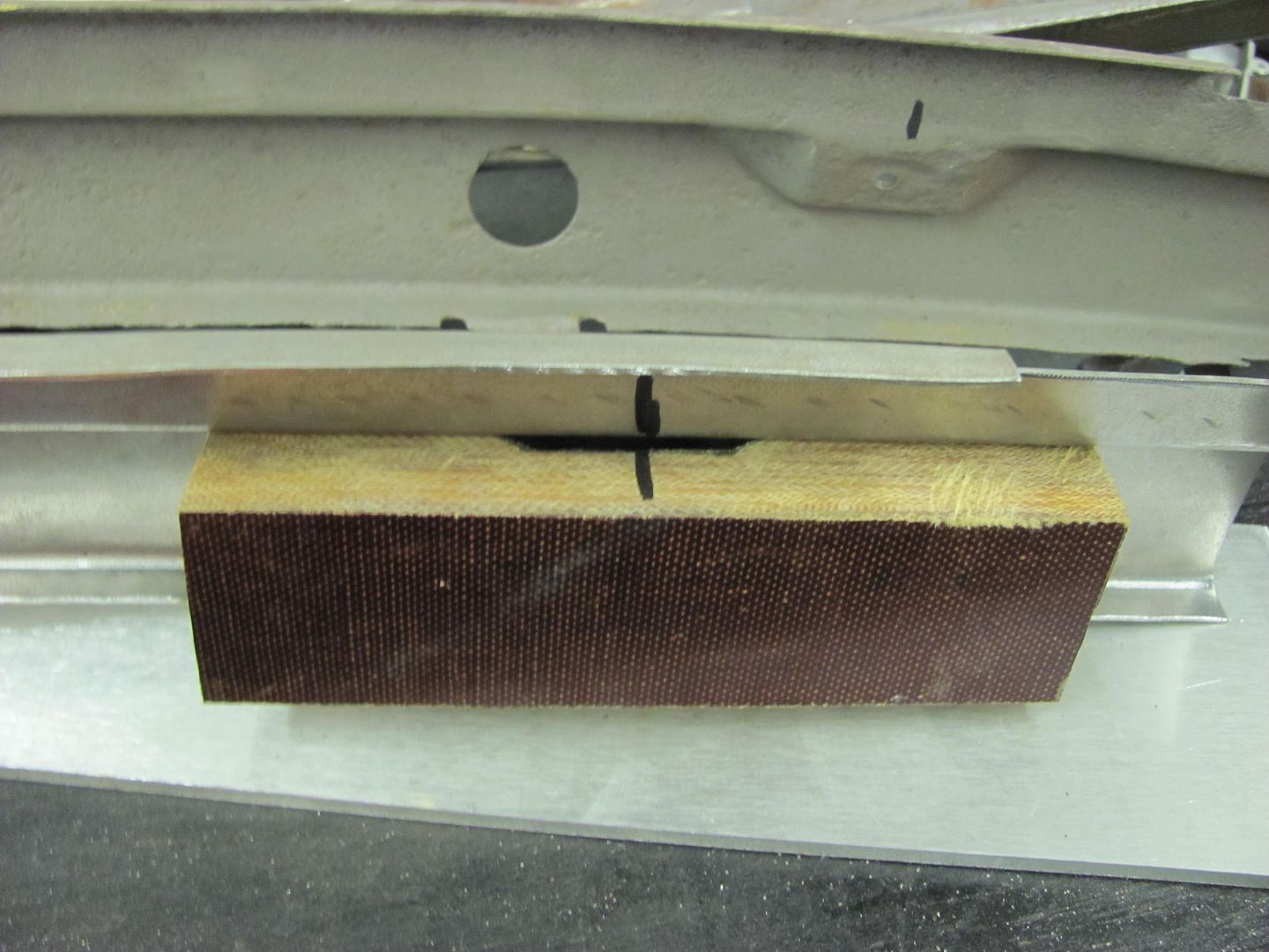
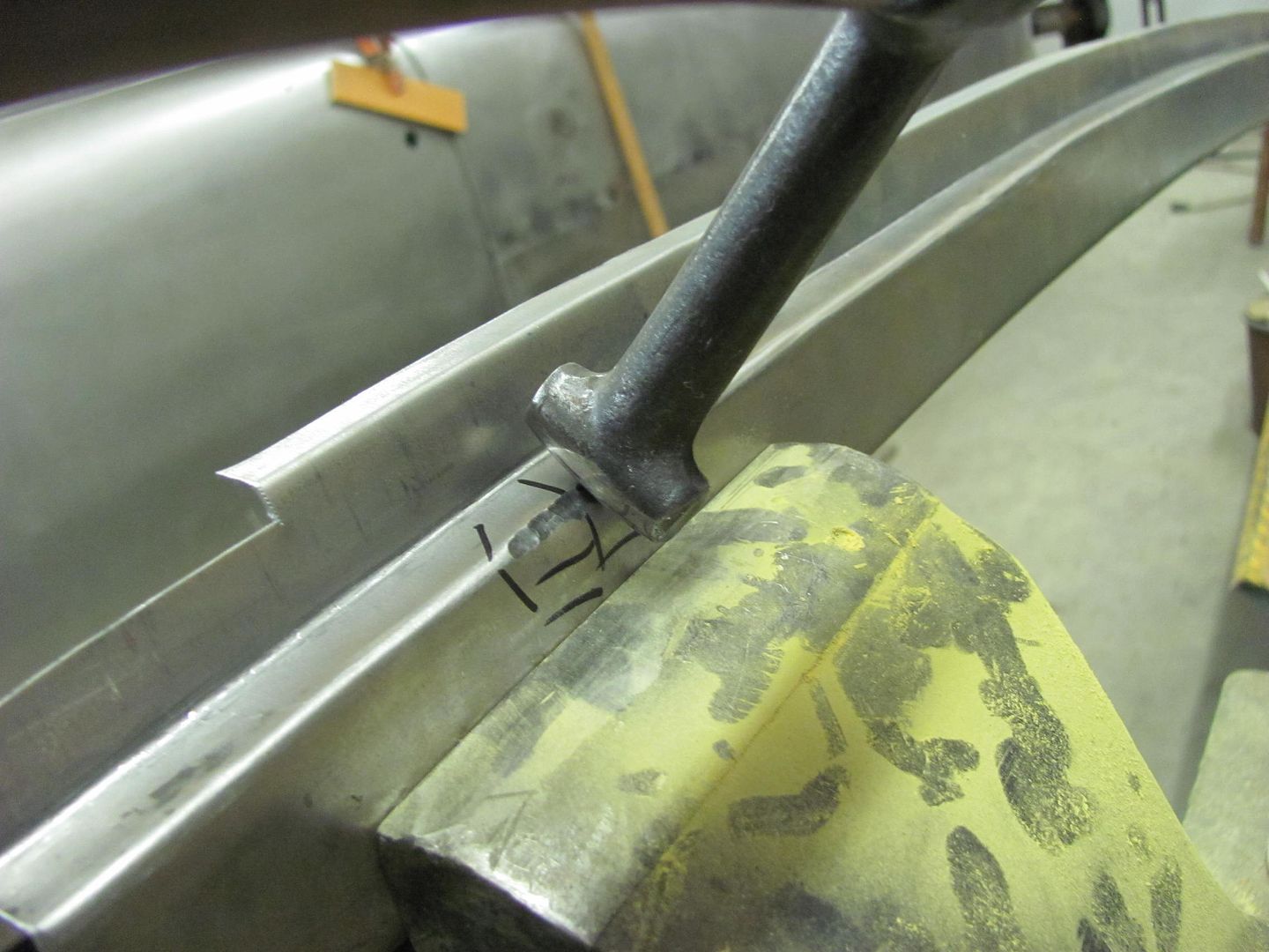
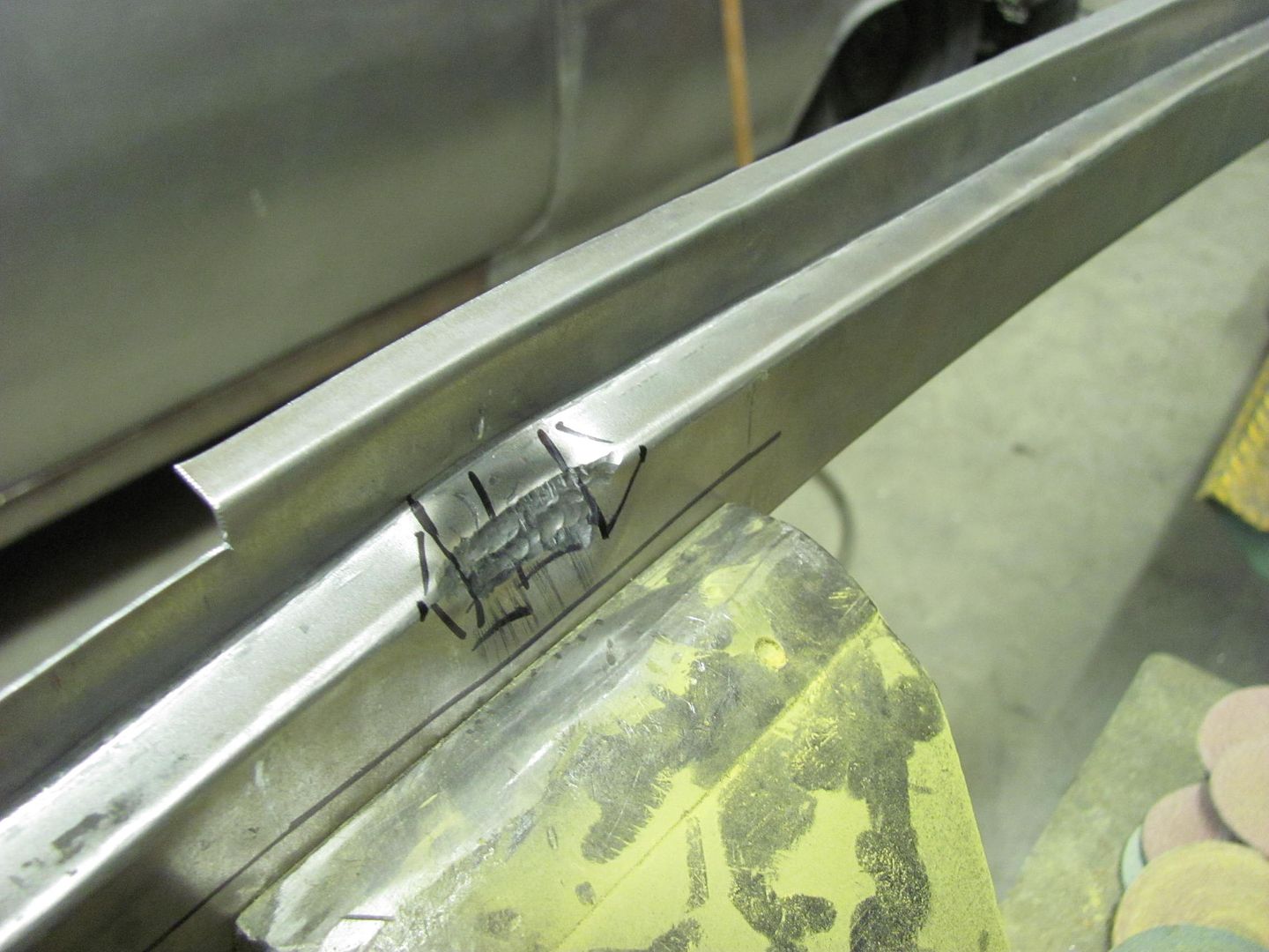
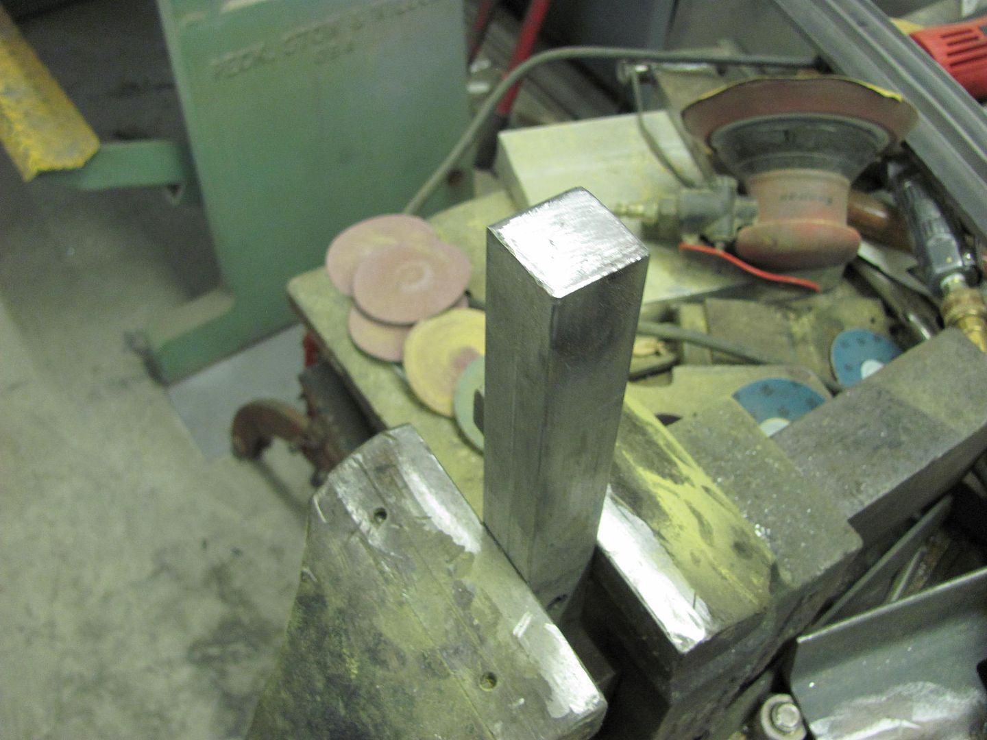
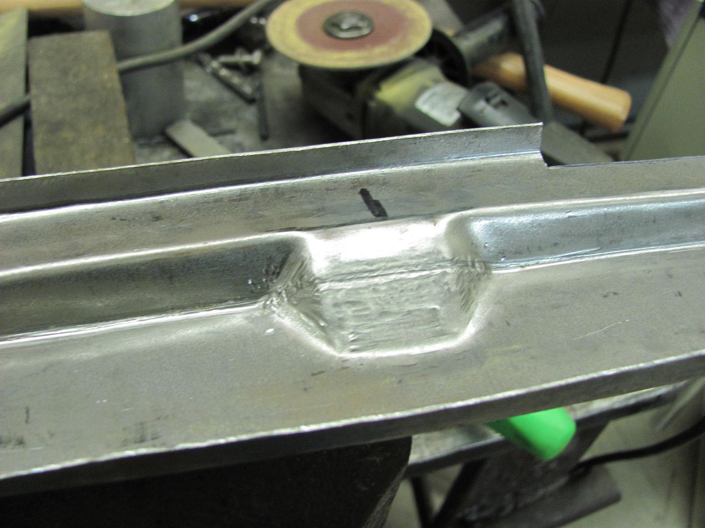
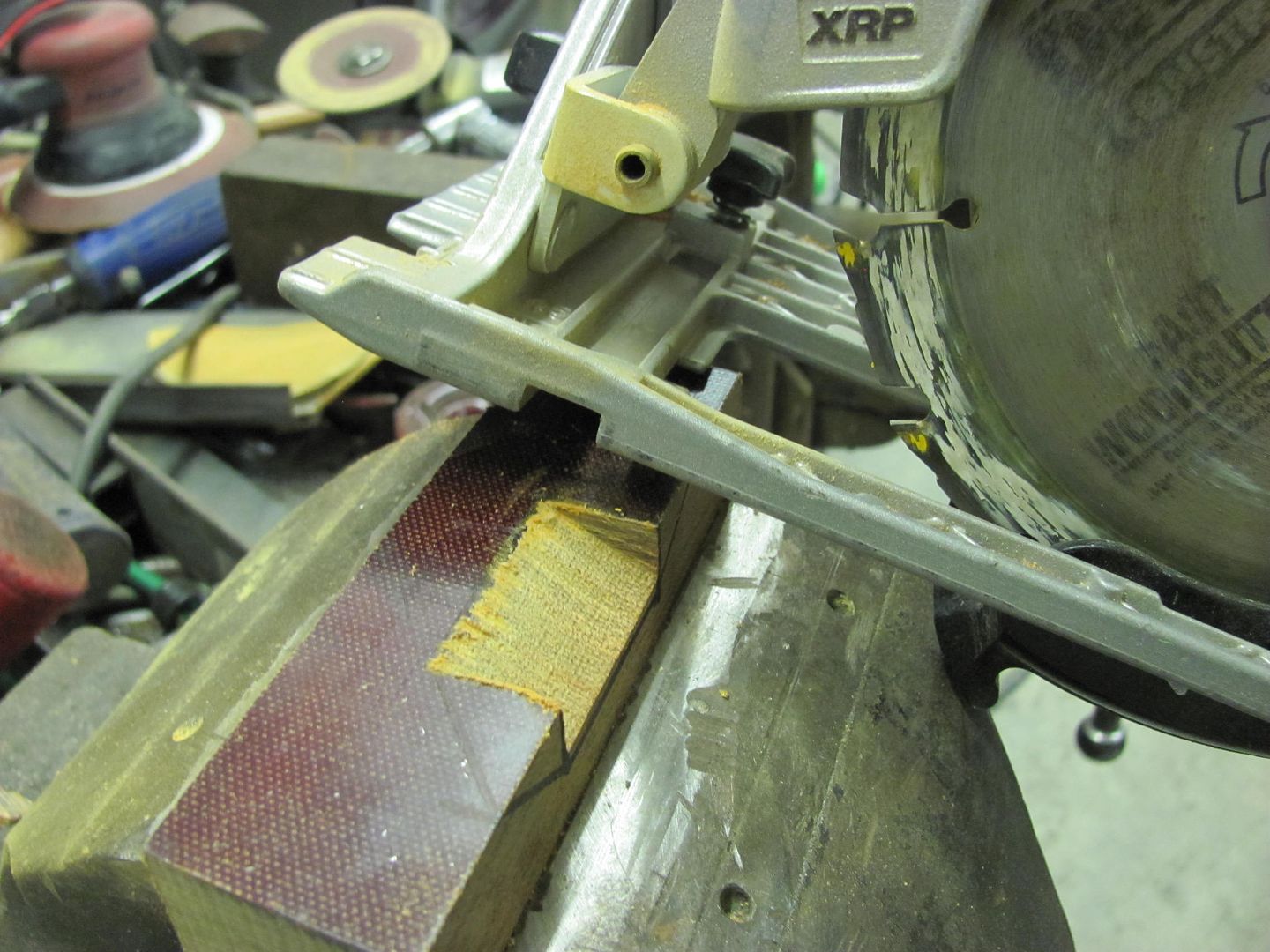
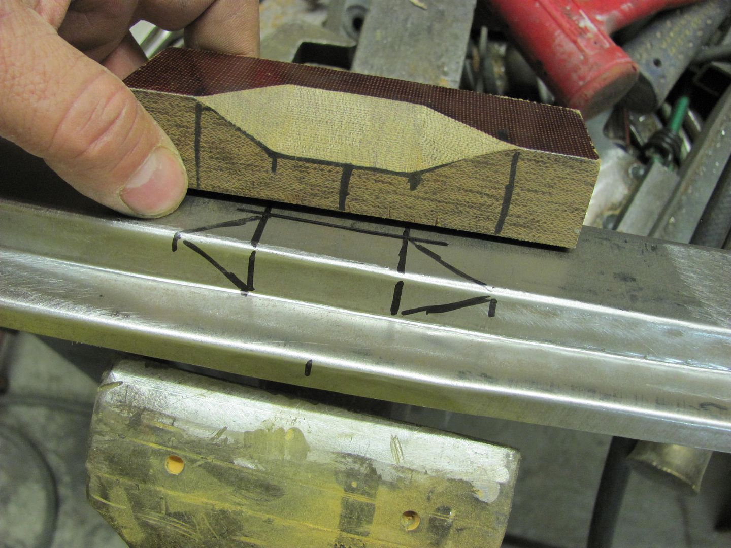
The heat marking is where he was attempting to braze it closed, with little success. Calipers showed the pan to be 14 ga, and I just happened to have some in stock. I've used the bead roller before to form a radius, but never on metal this thick before. This will be a good test of the fancy 75A durometer skateboard wheel to see how well it works.


Picture236.jpg


Picture238.jpg


Picture239.jpg


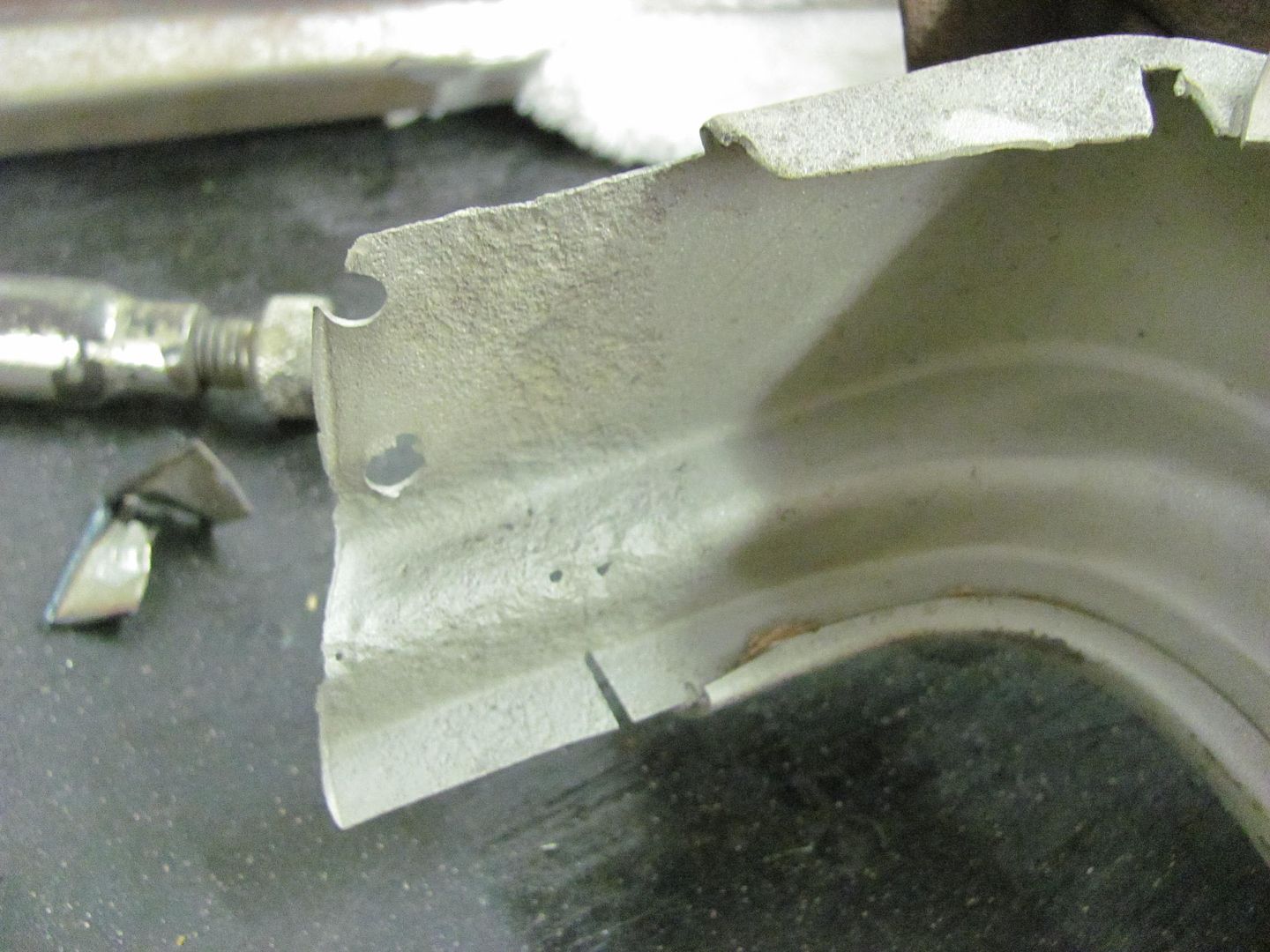
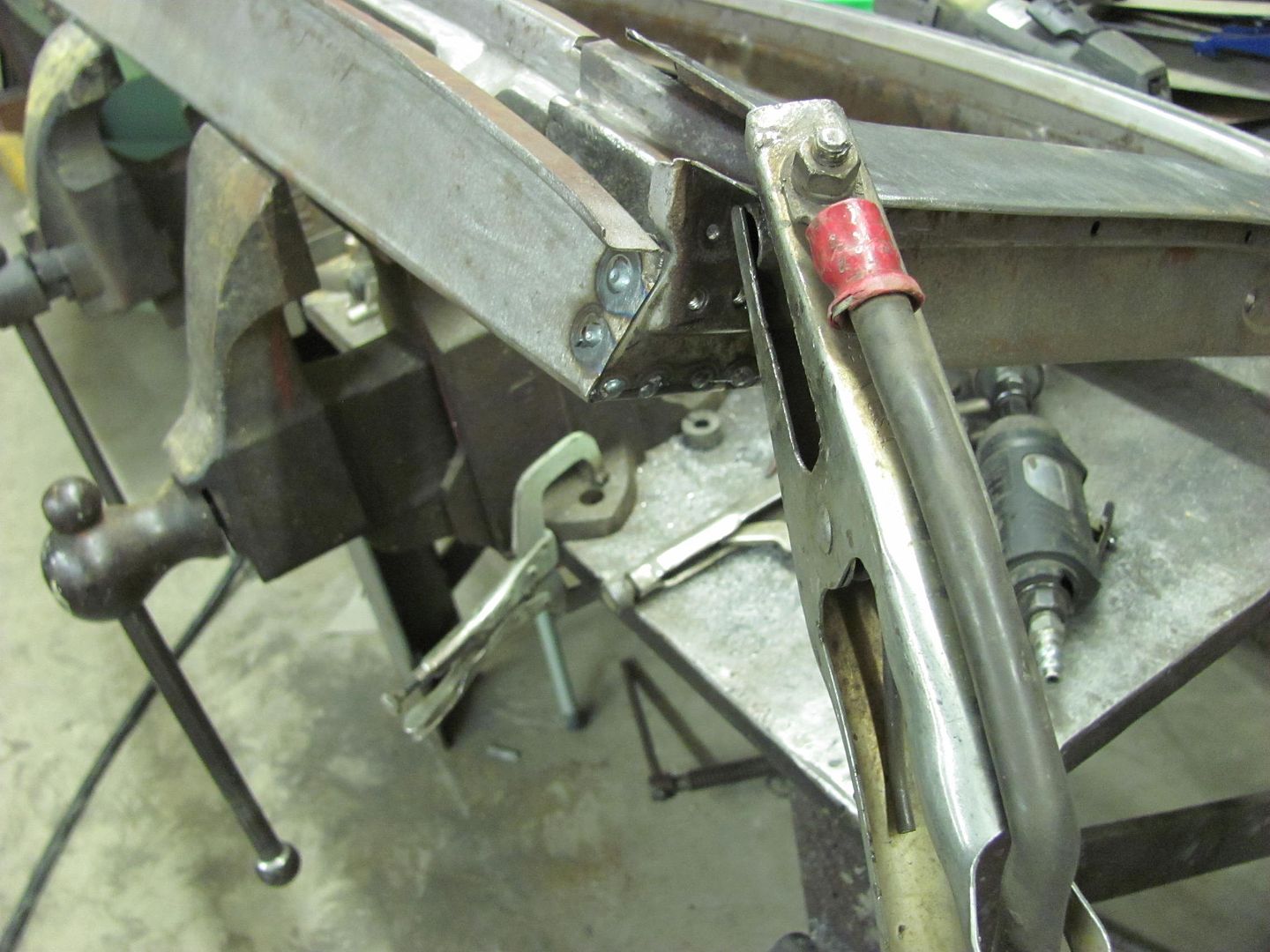
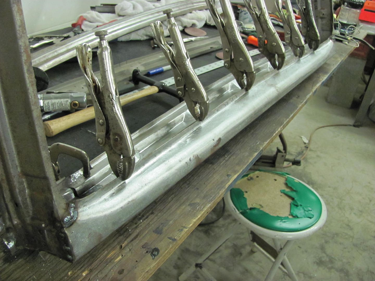
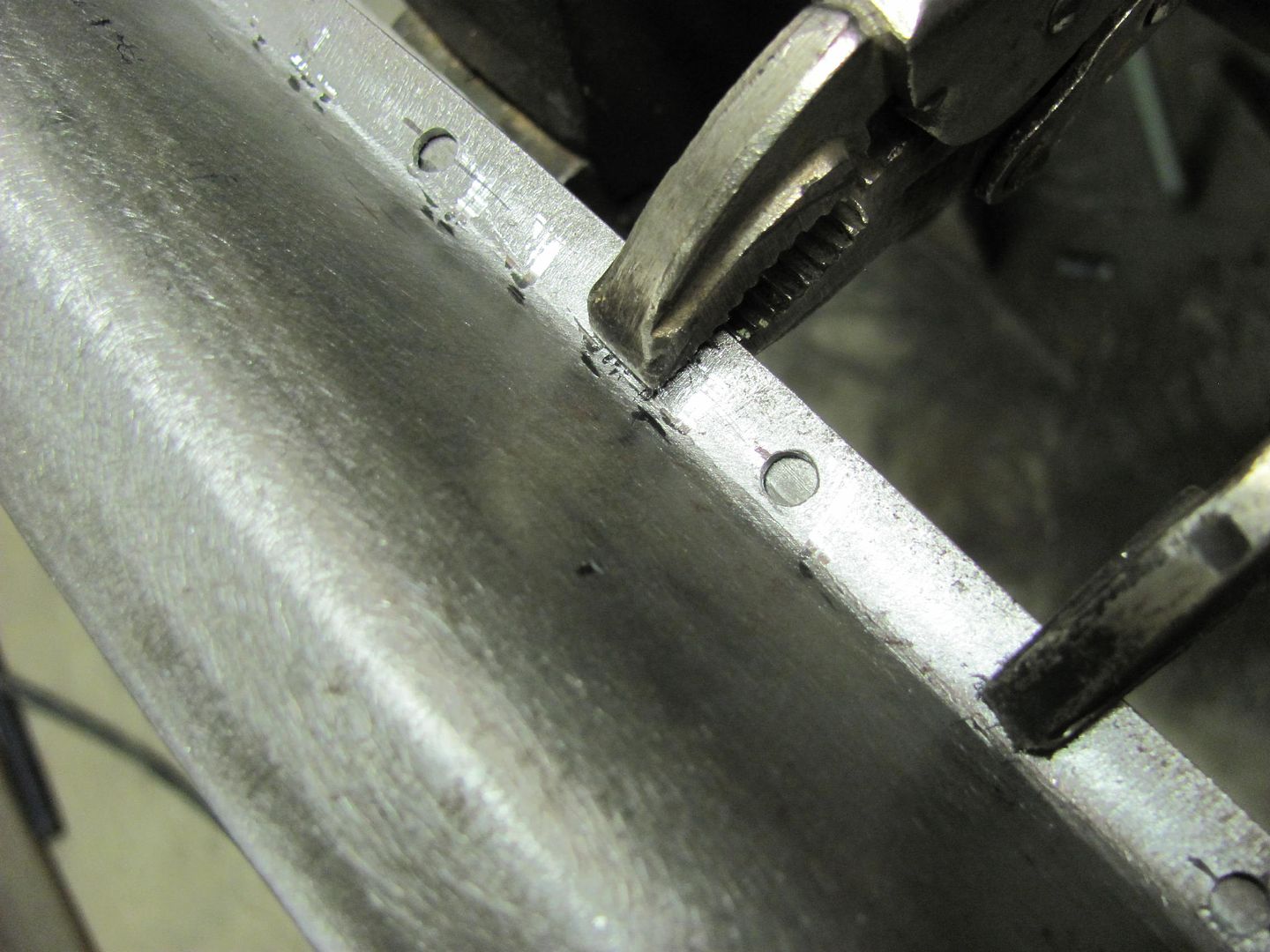
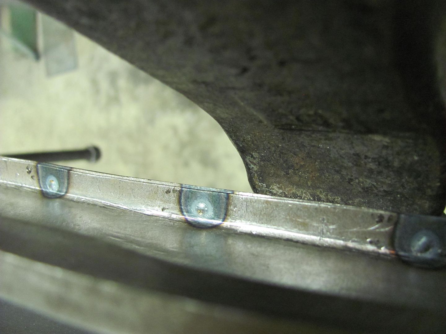
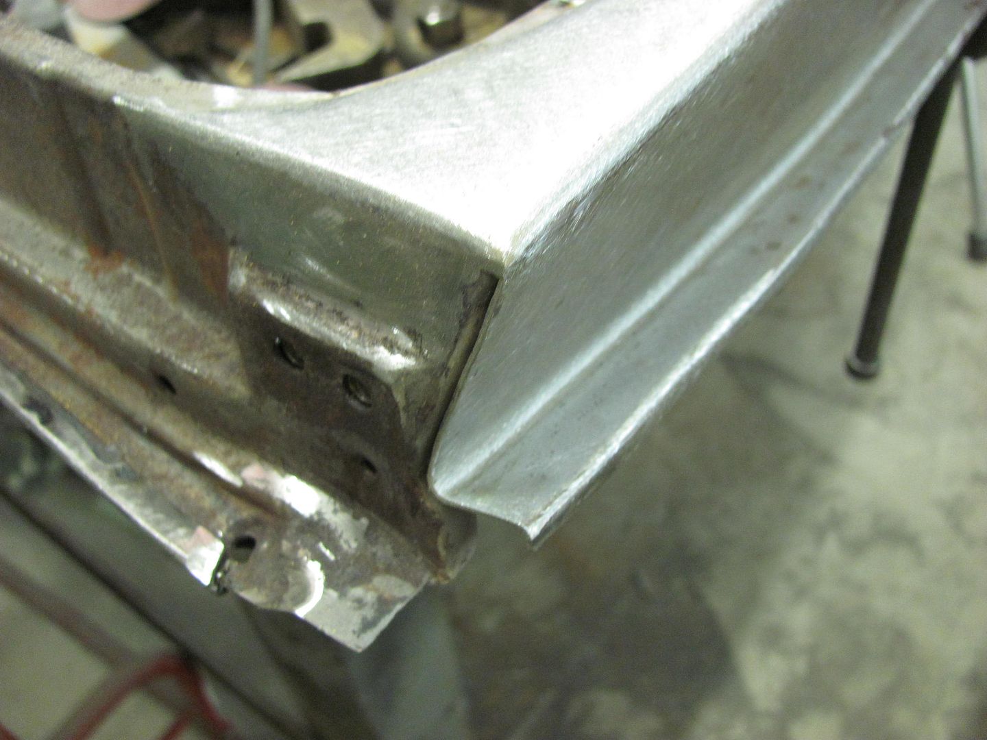
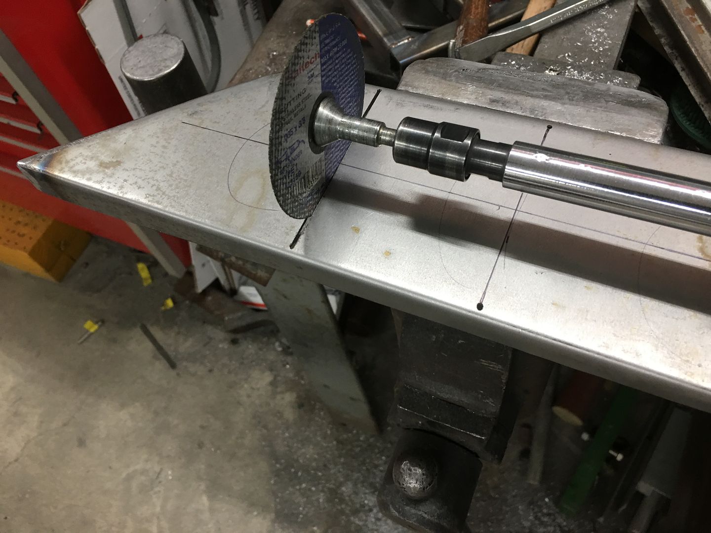
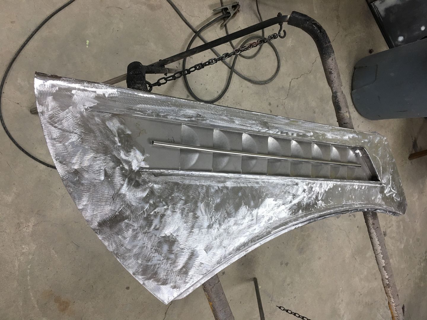
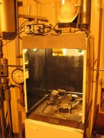
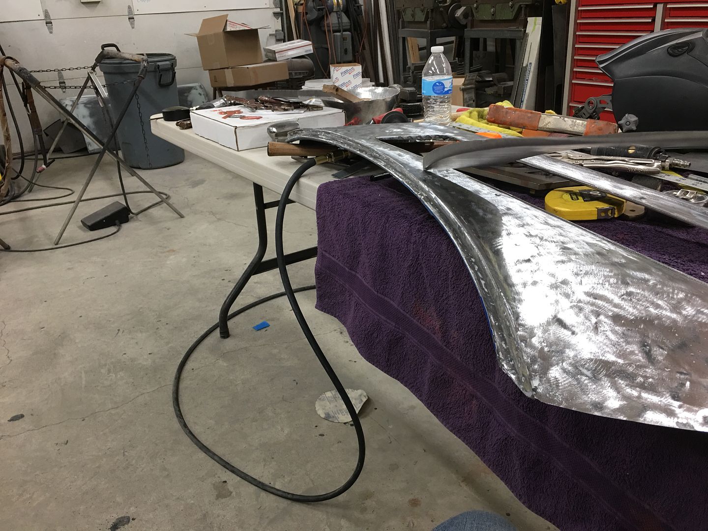
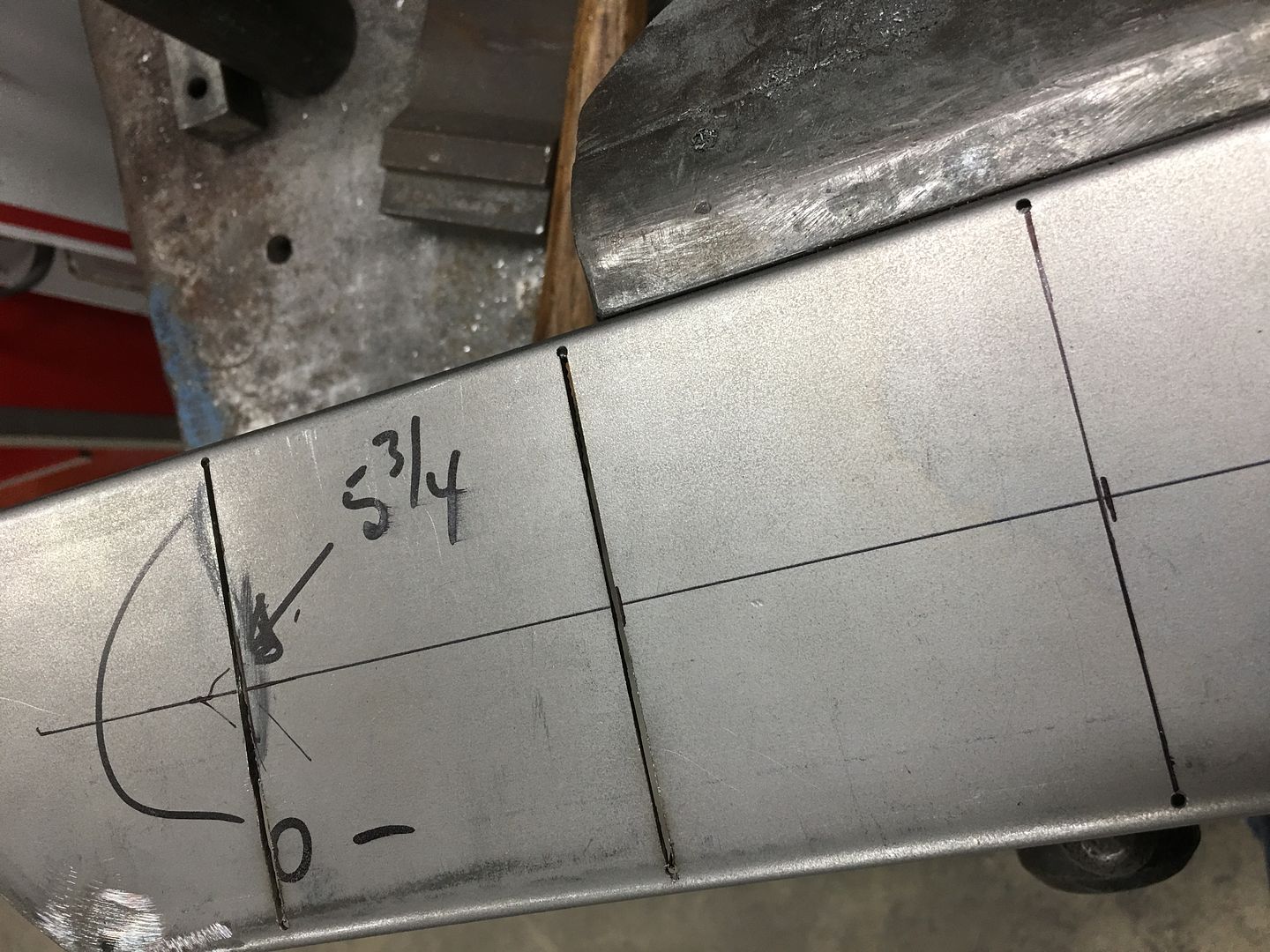
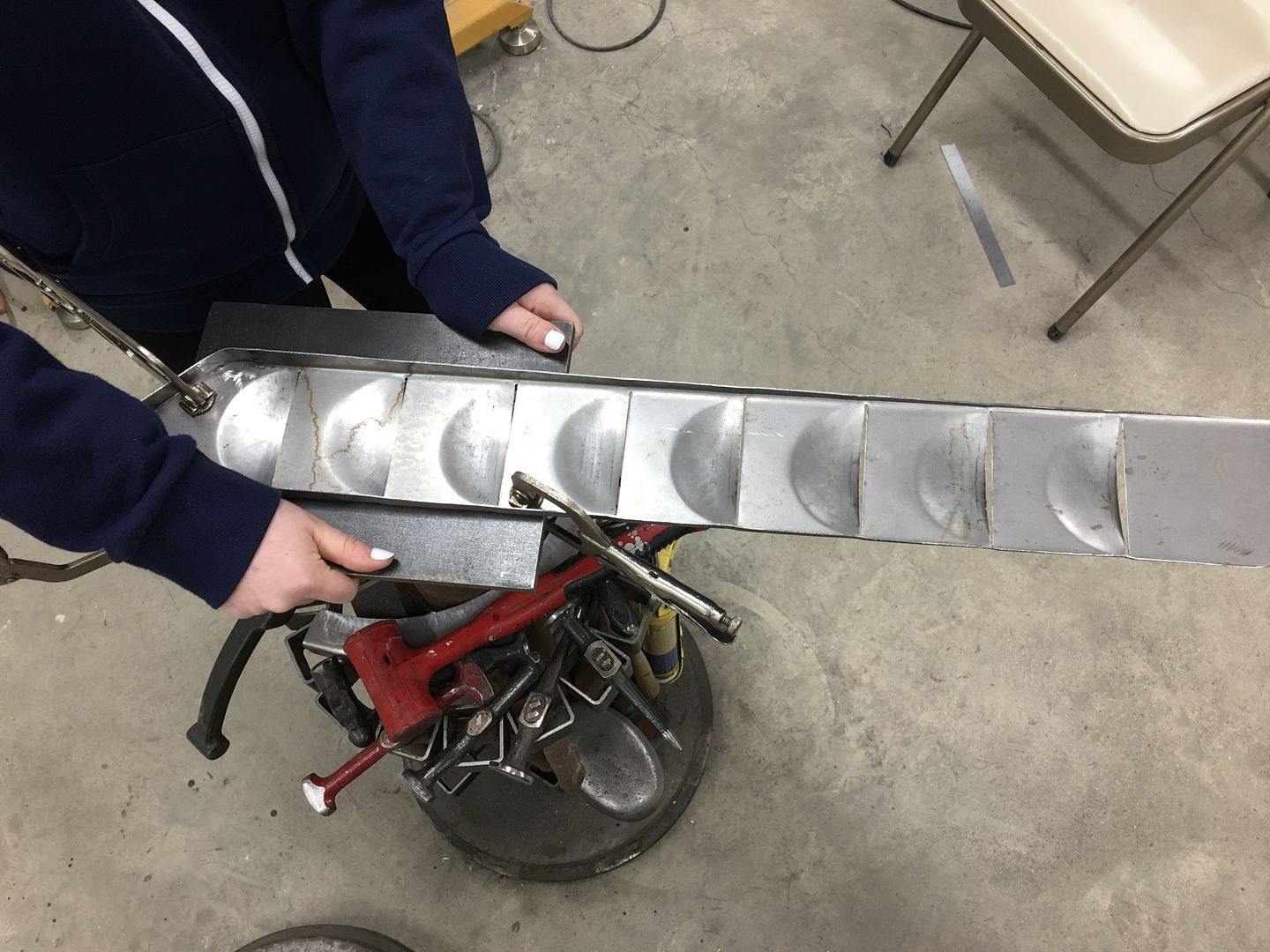
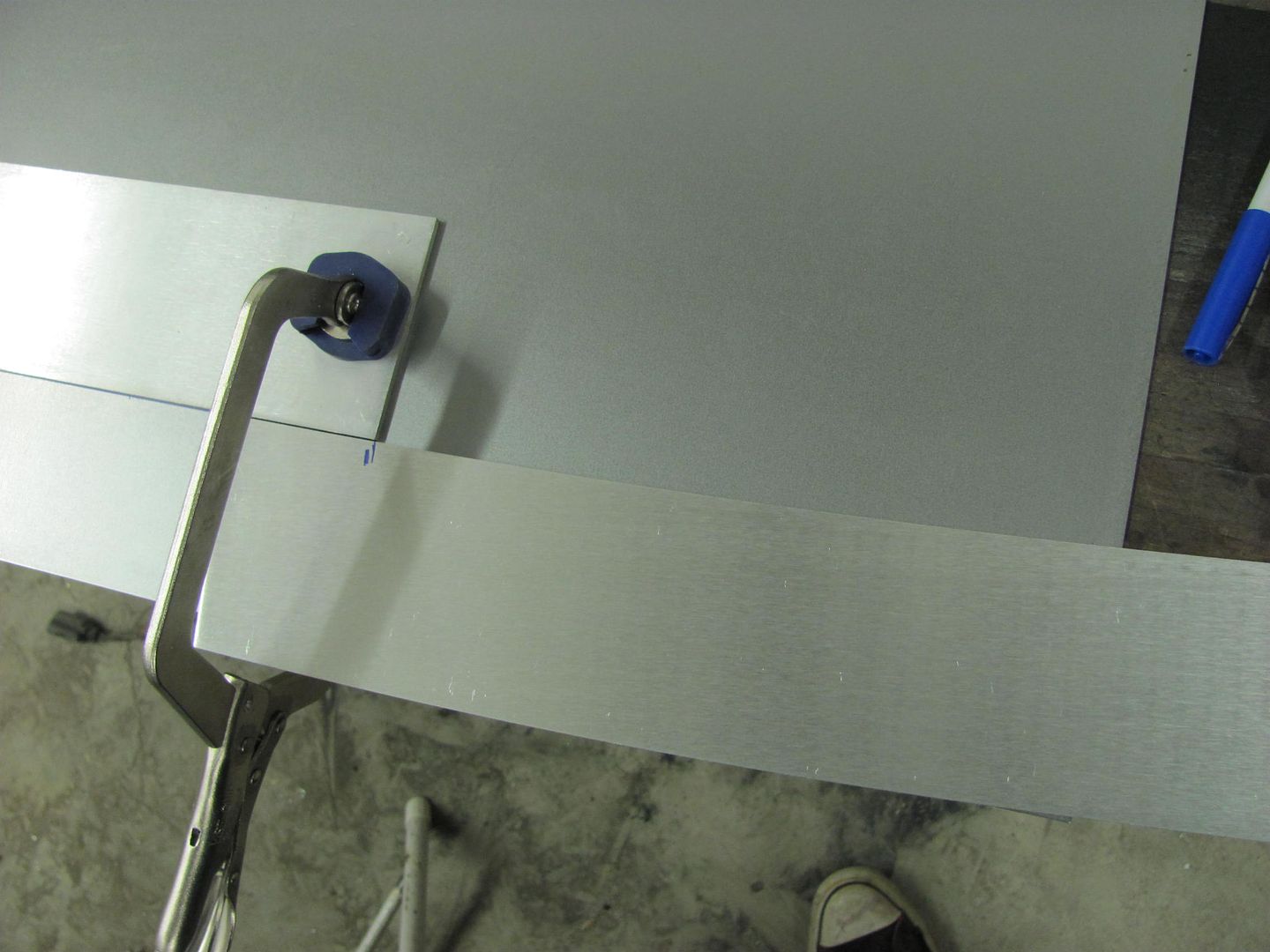
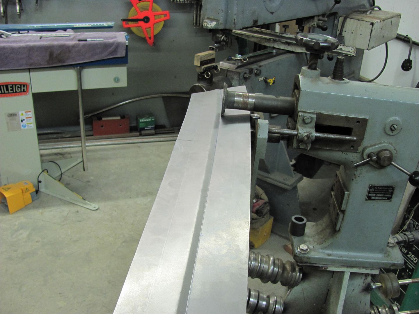
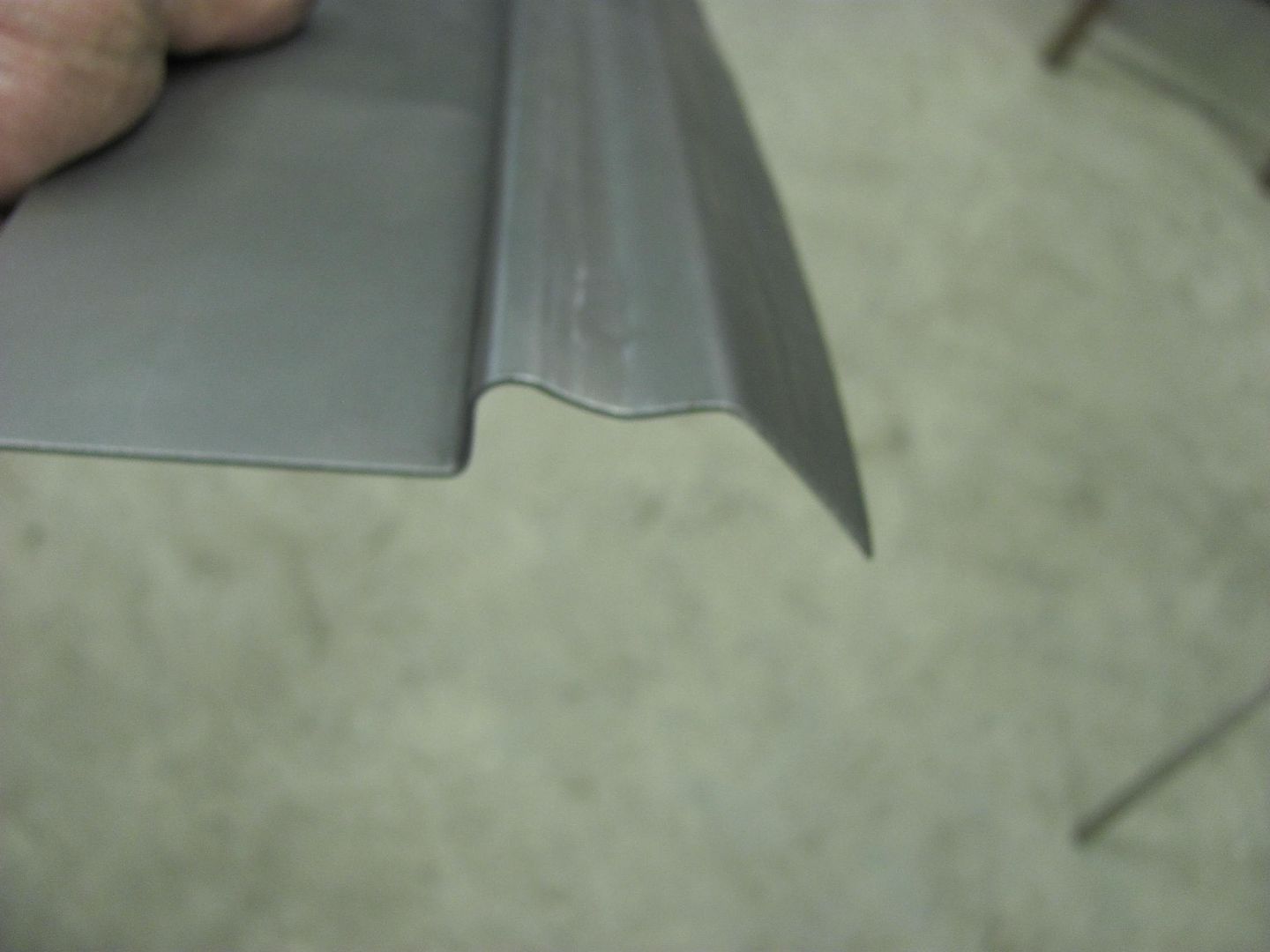
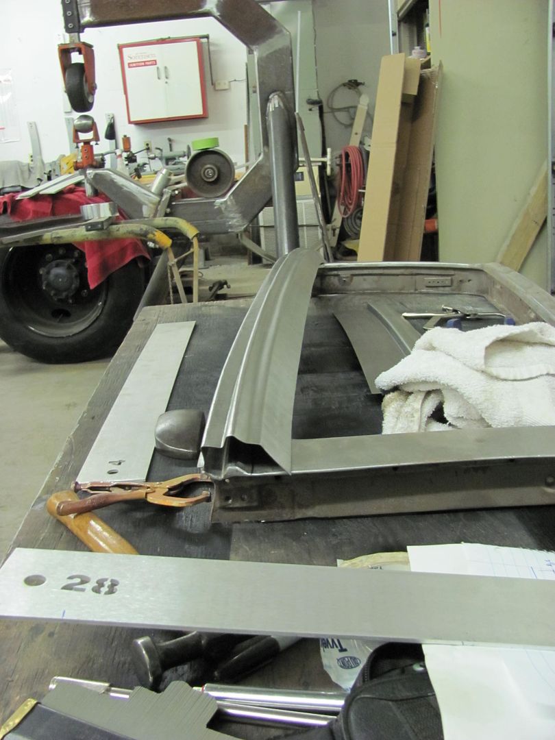
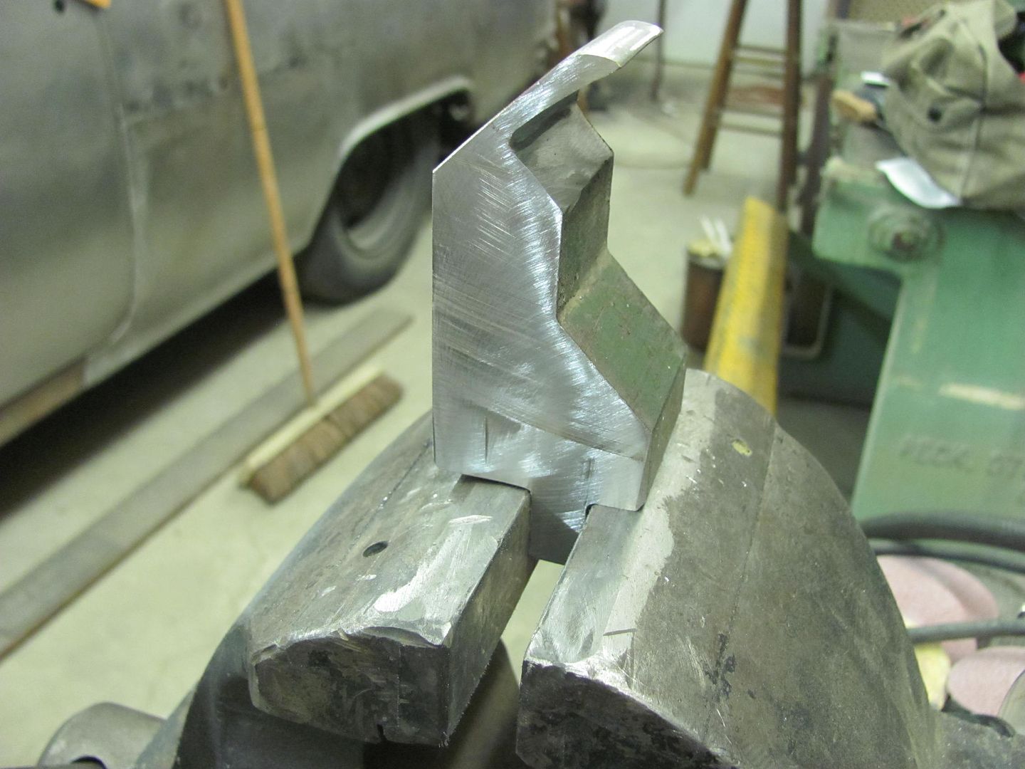
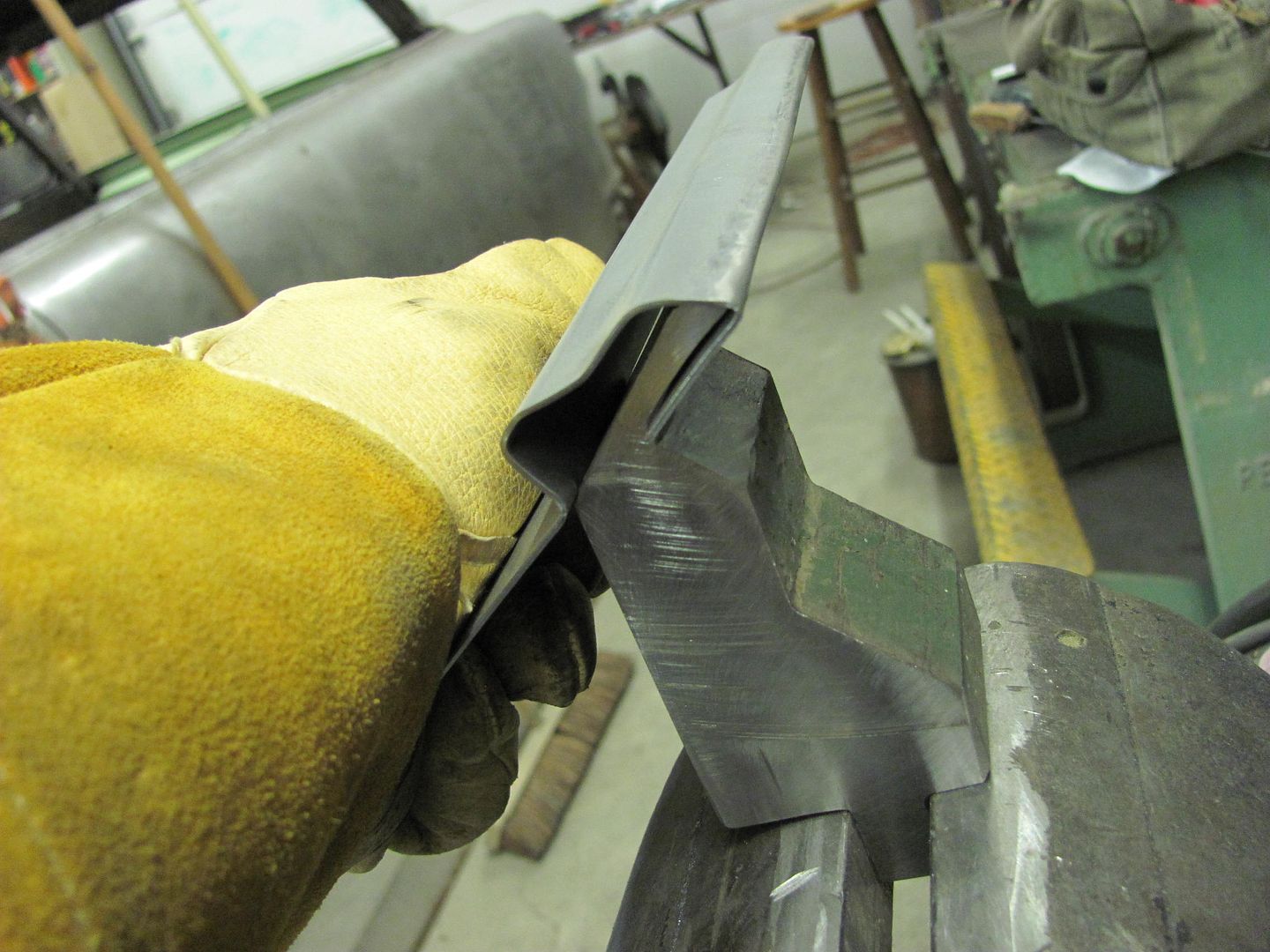
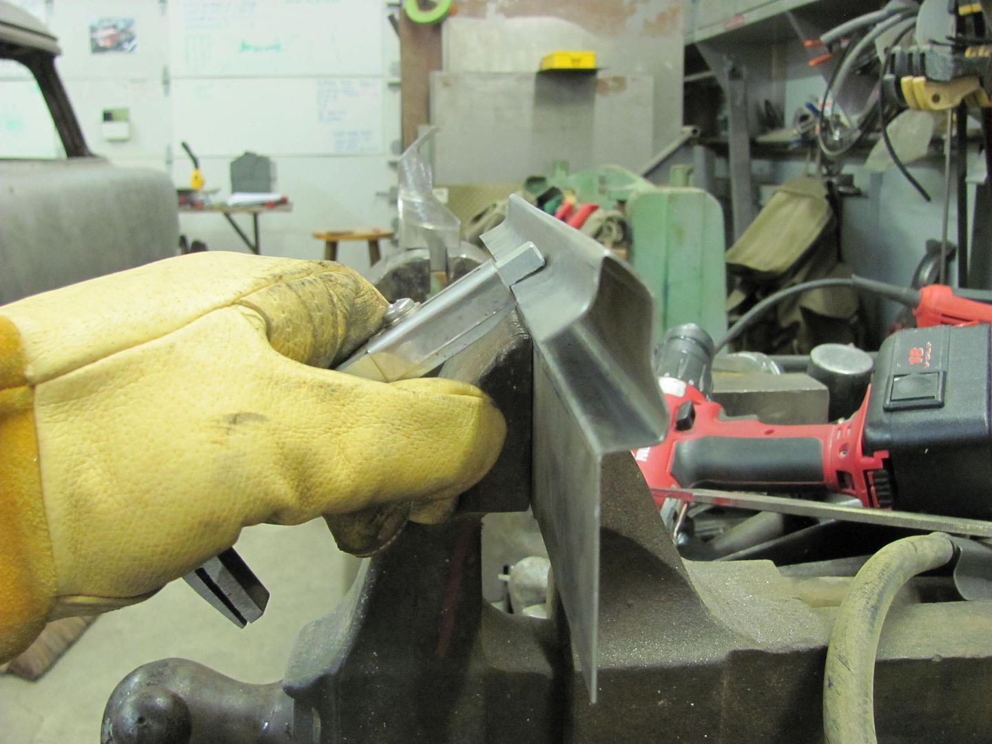
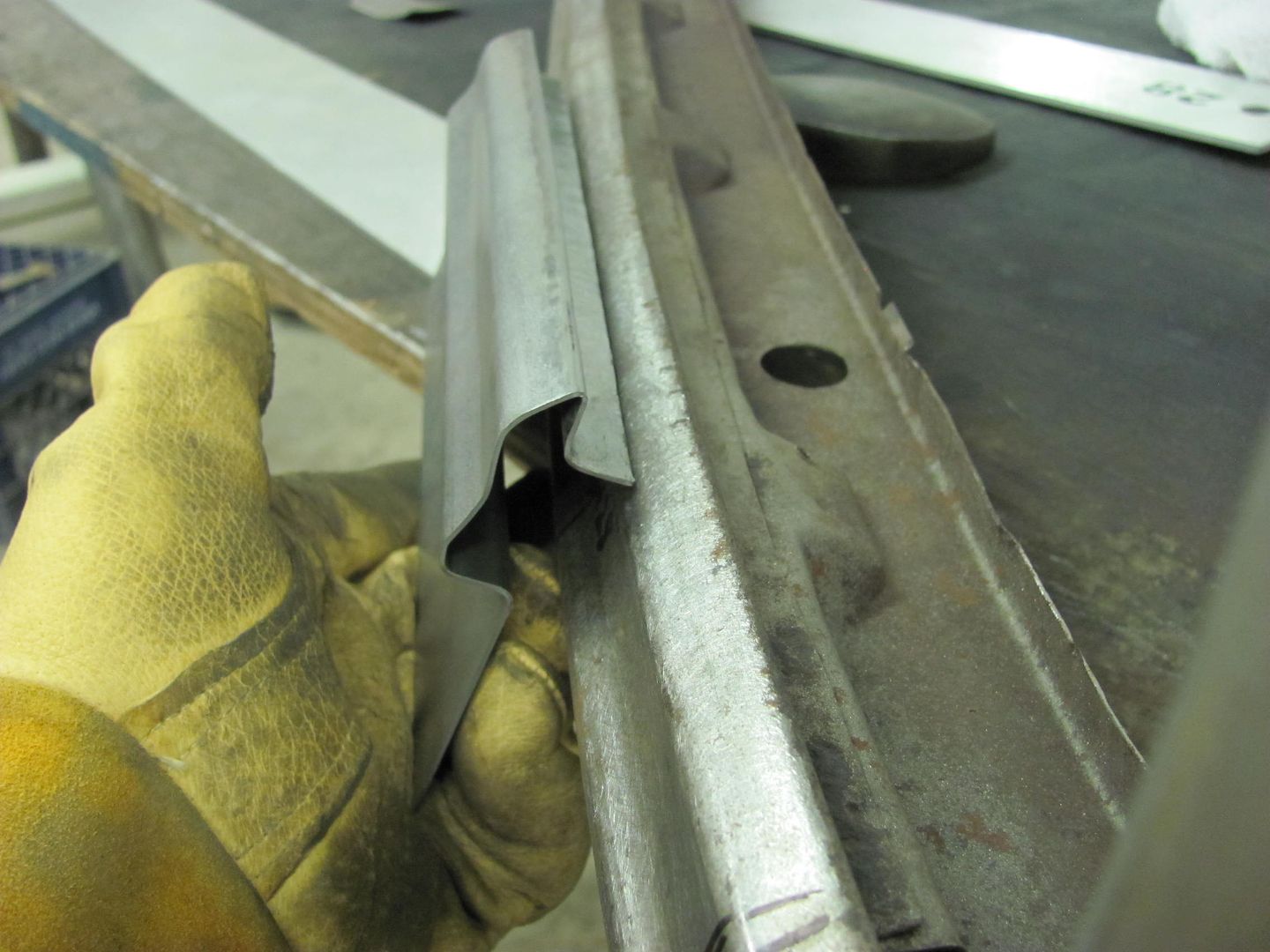
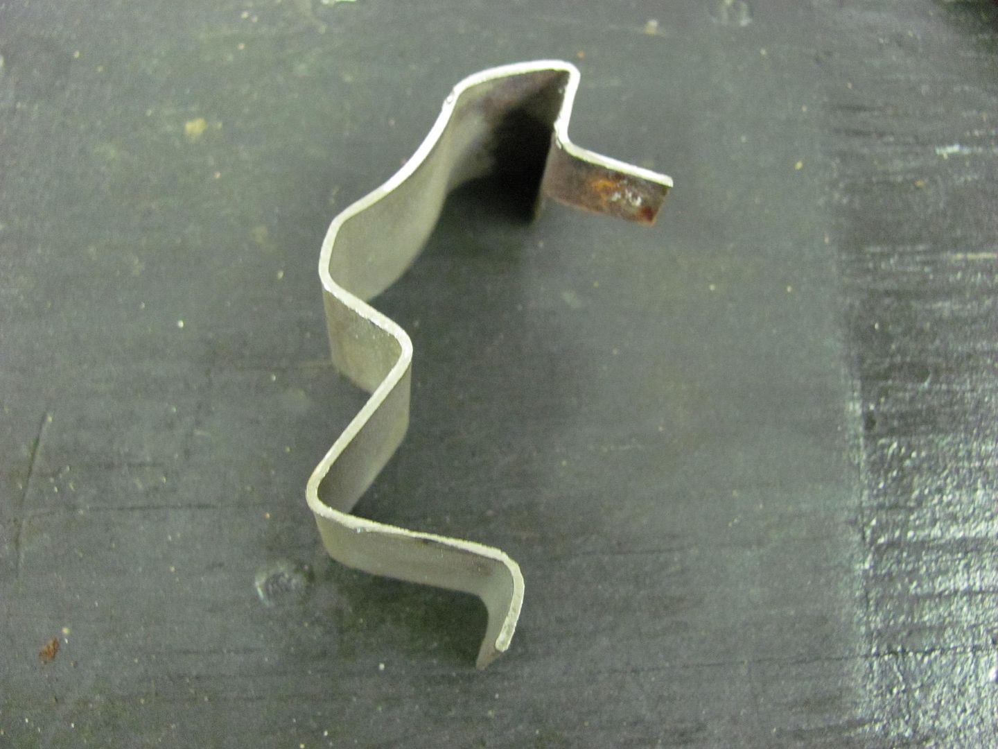
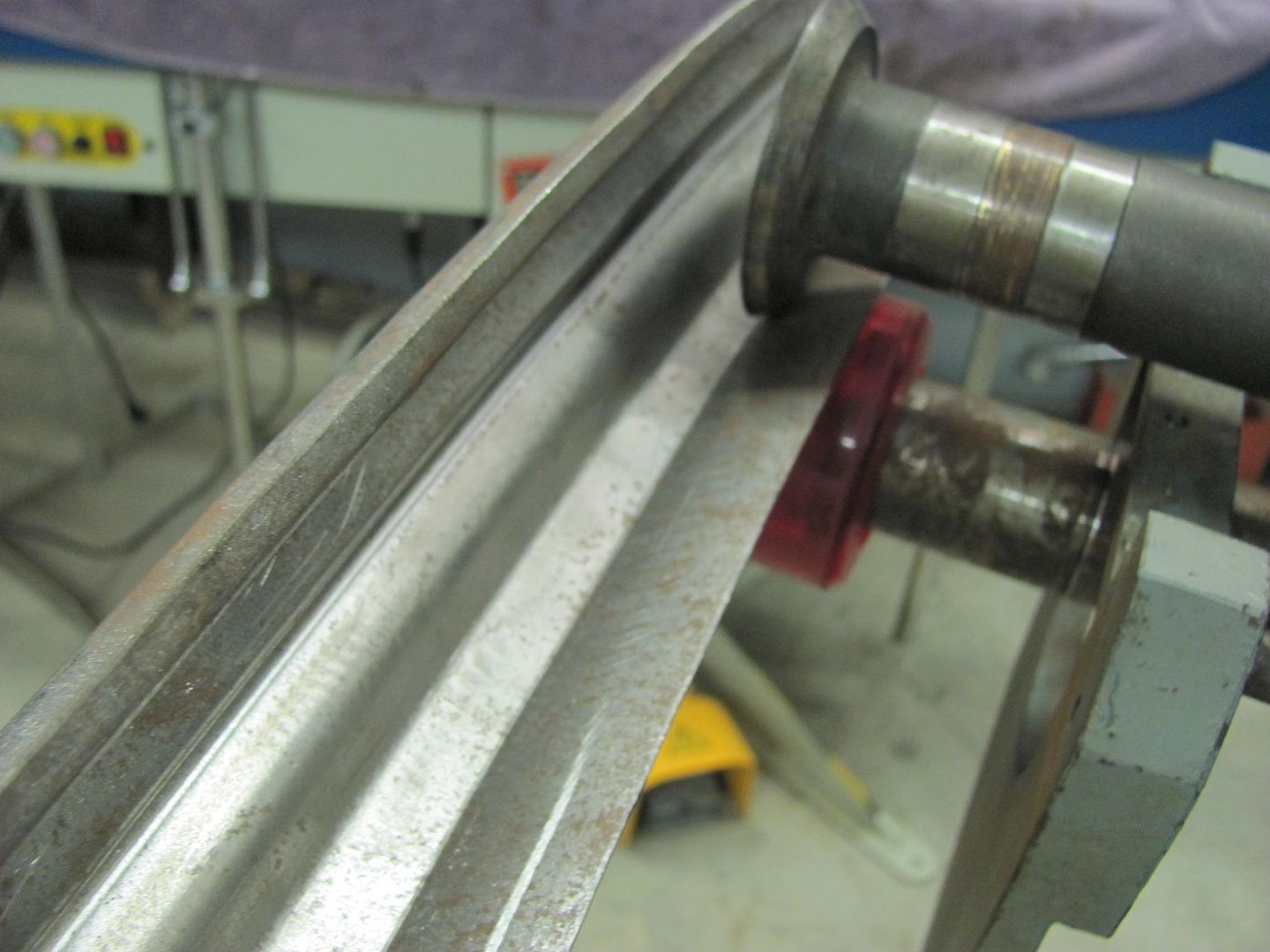
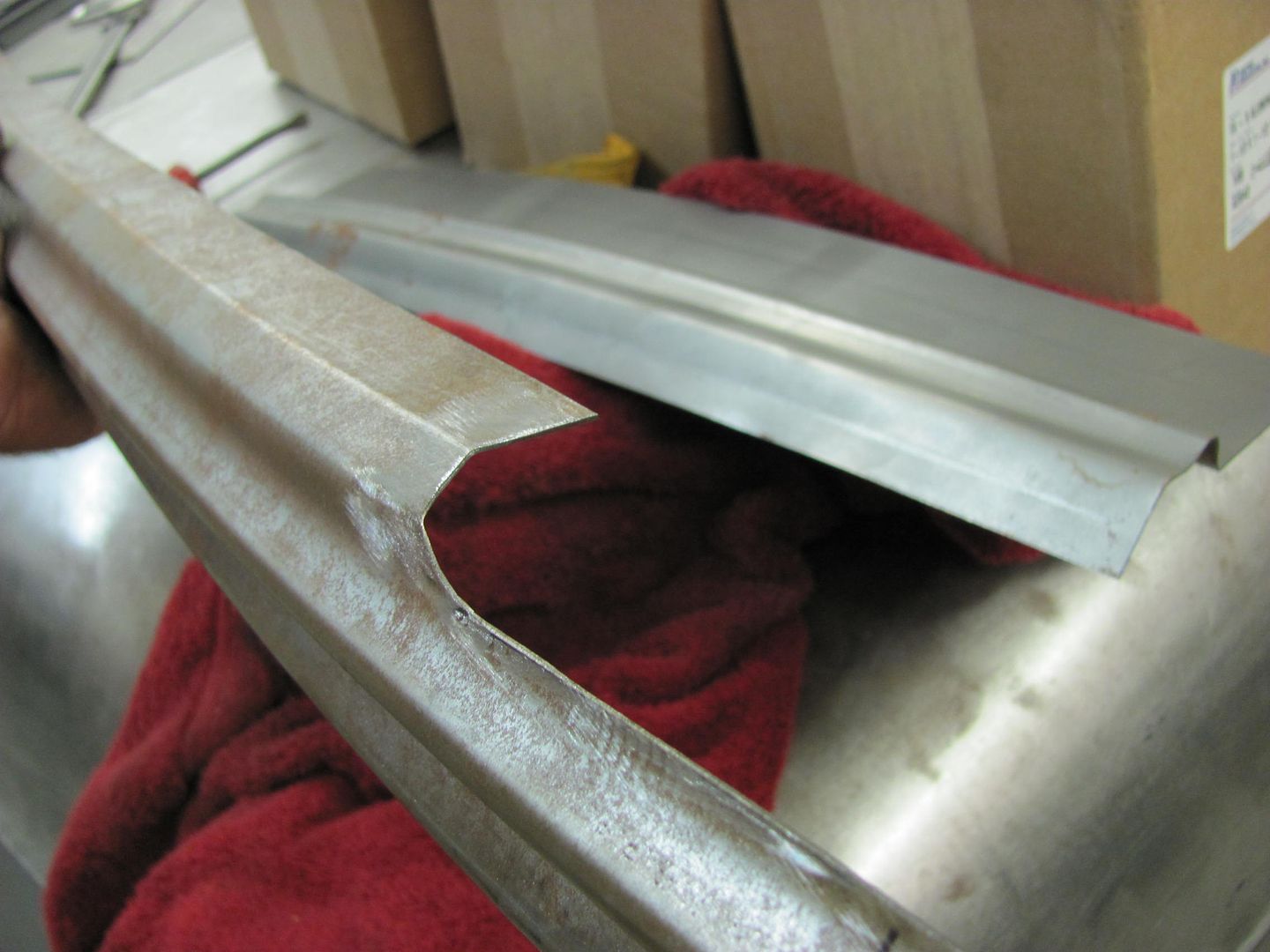
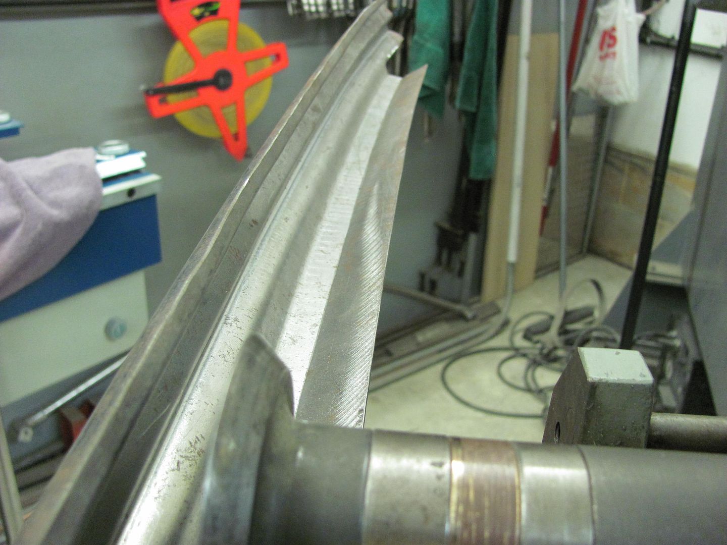
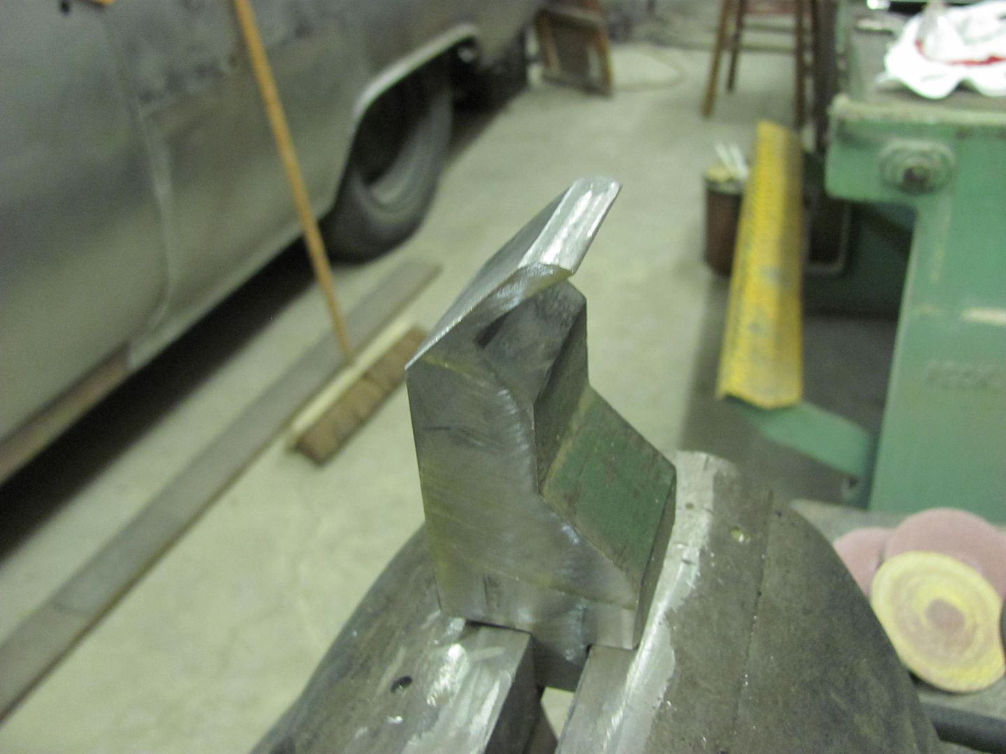
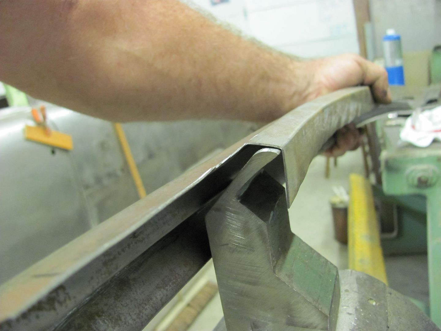
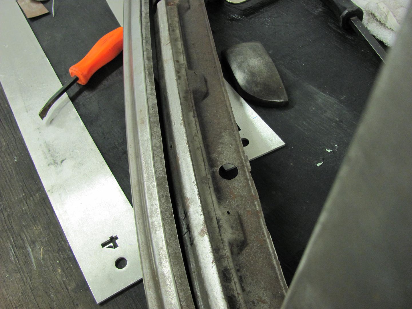
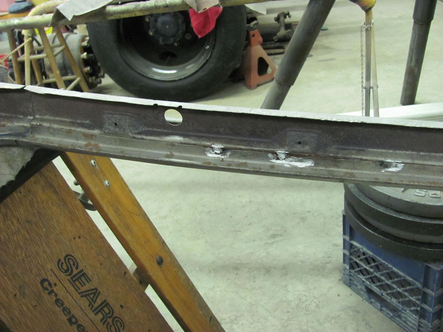
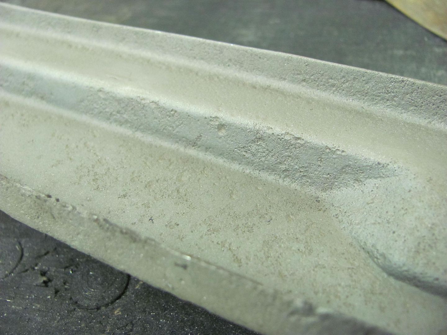
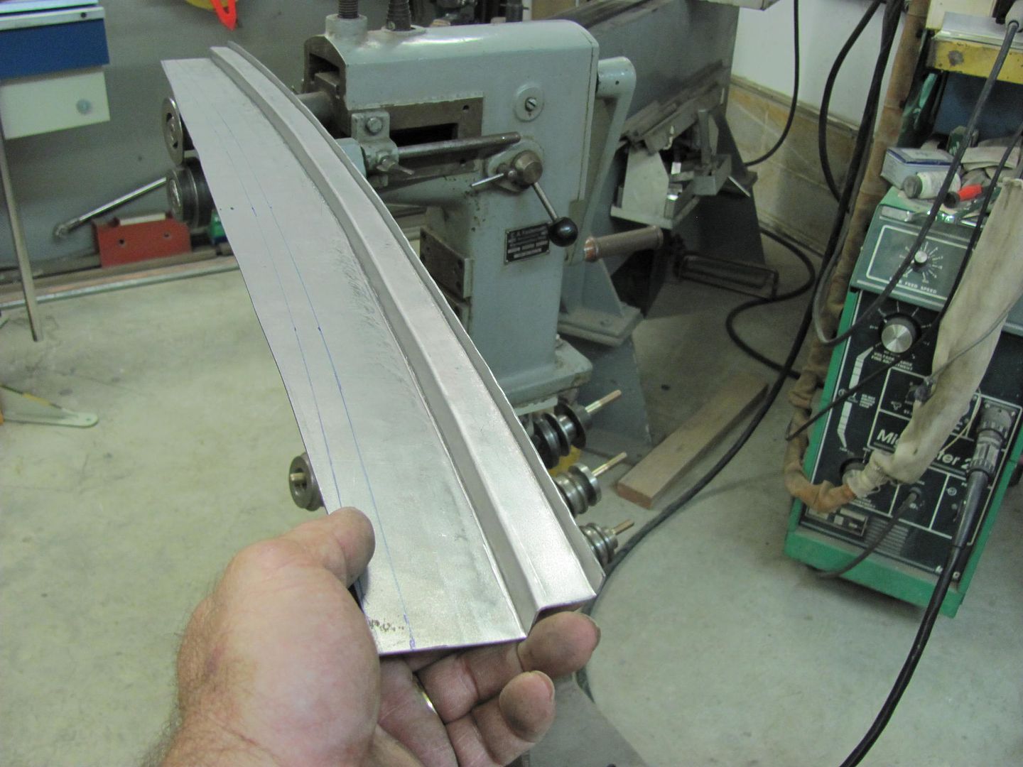
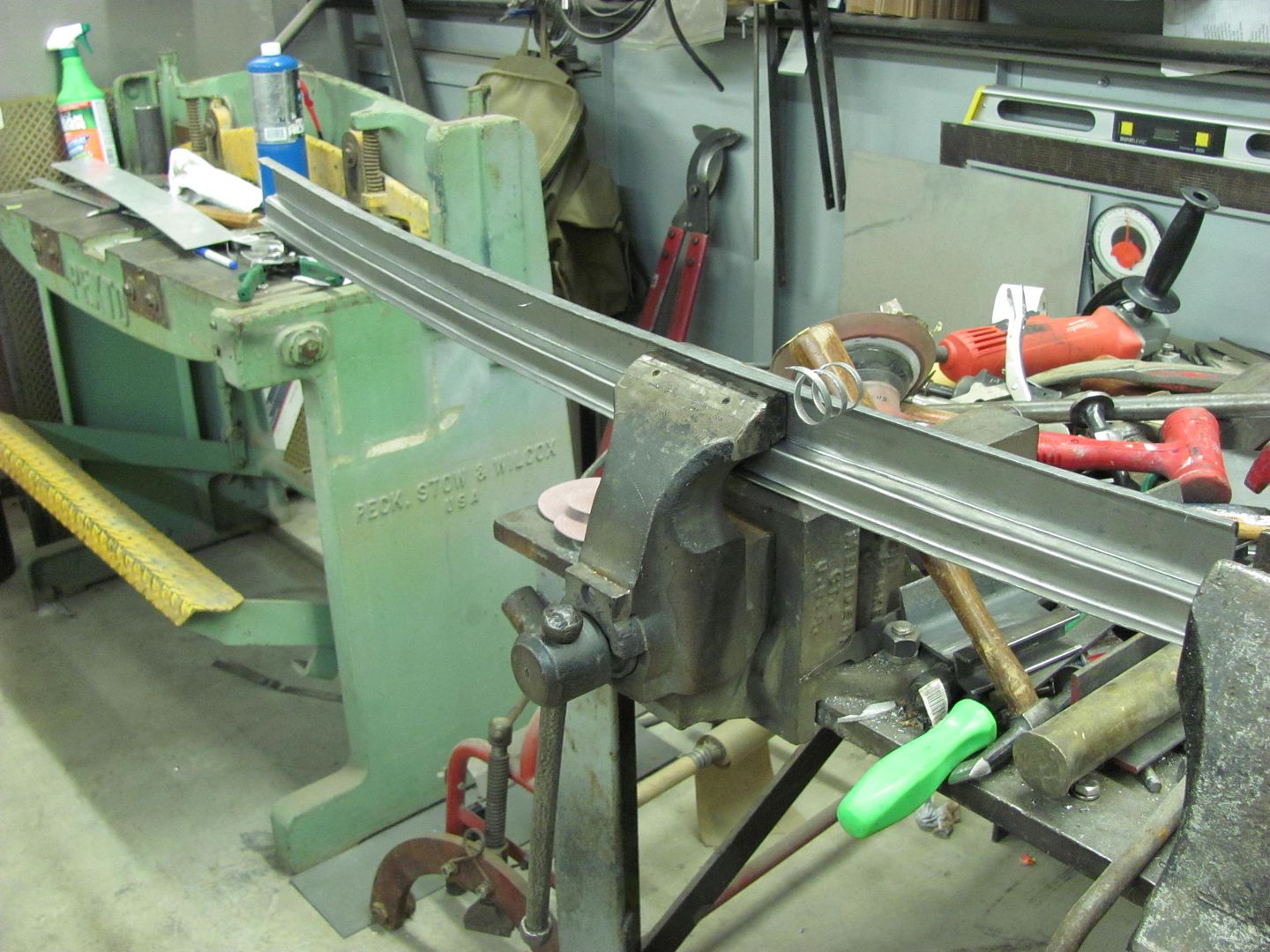
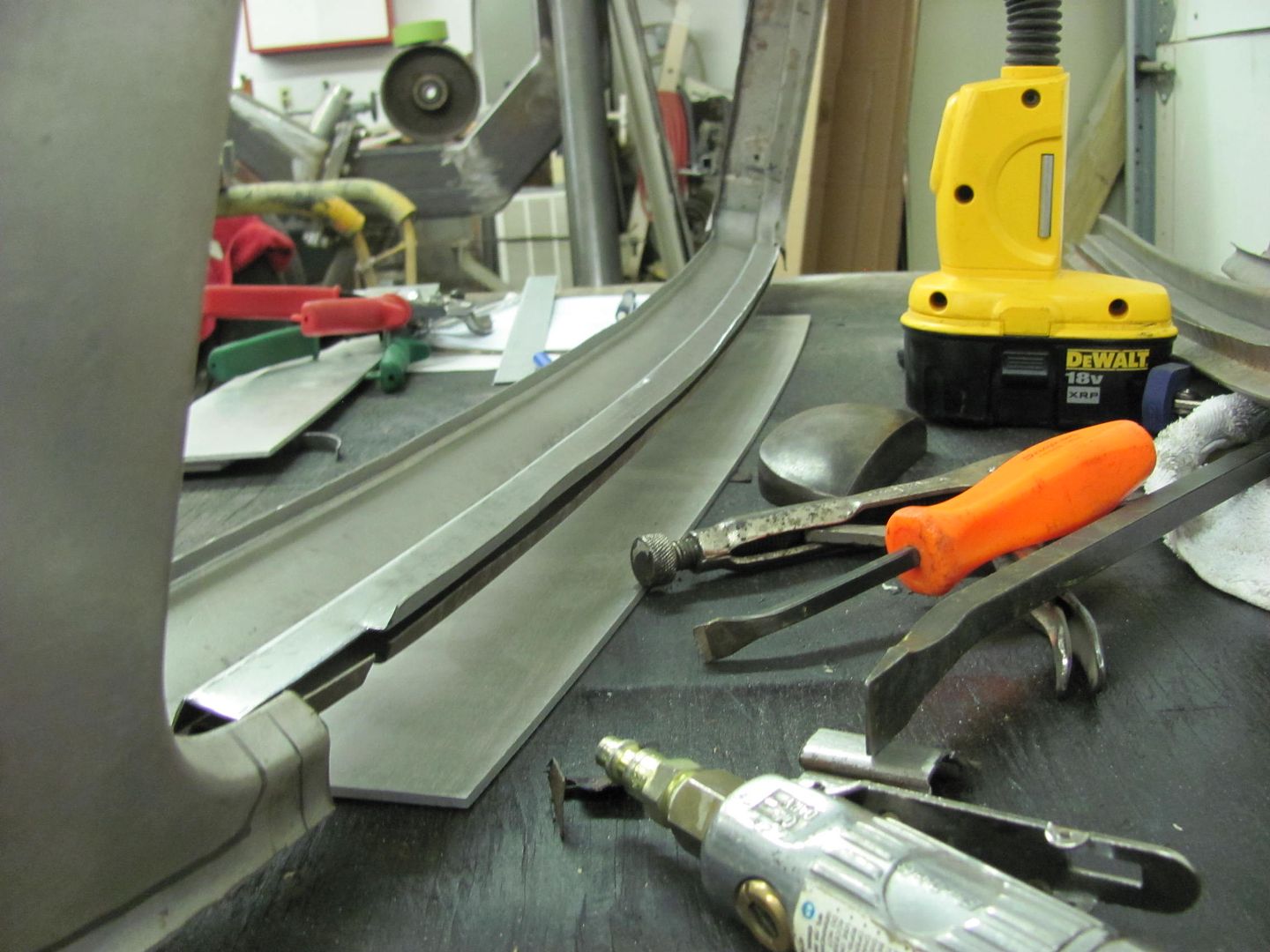
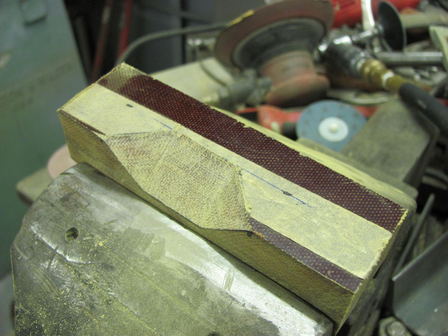
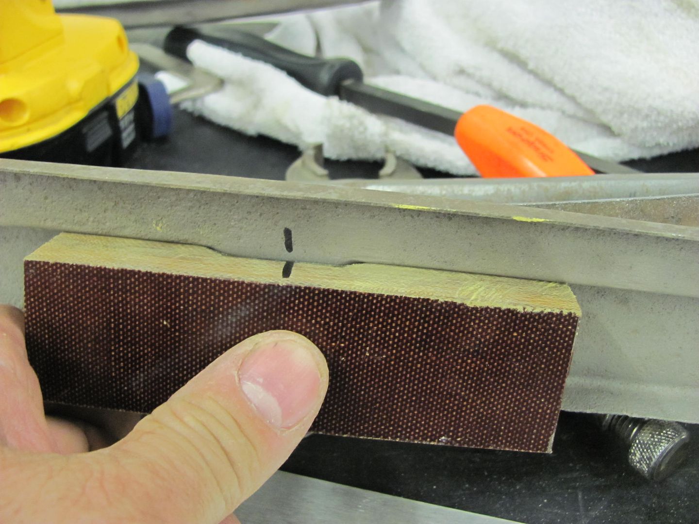
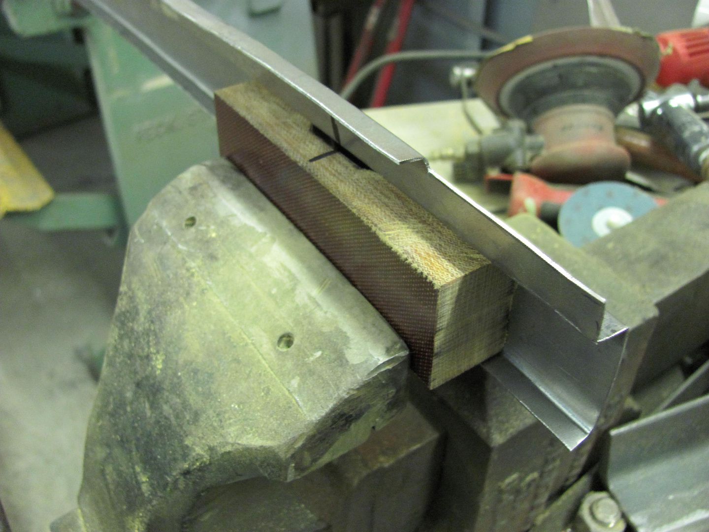
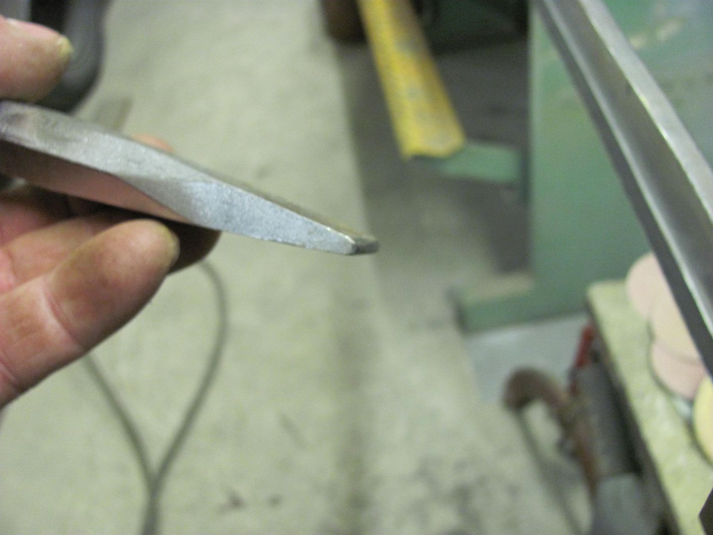
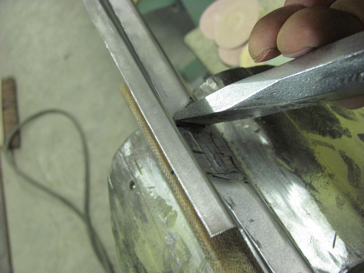
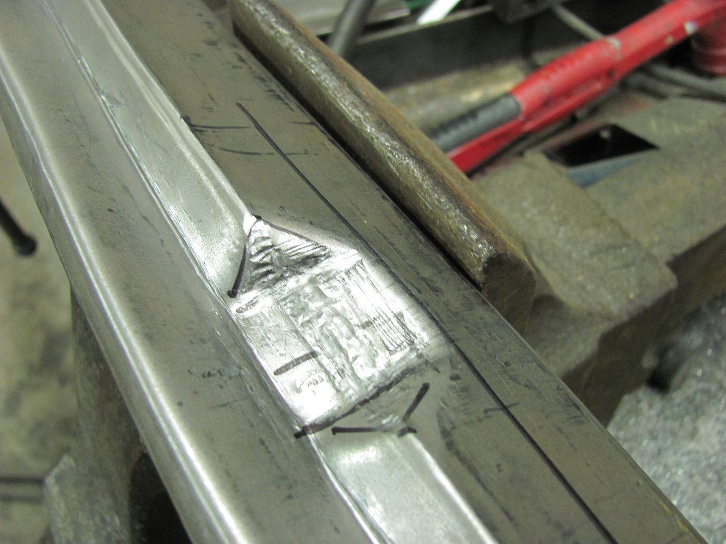
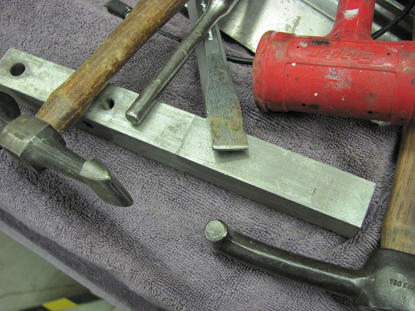
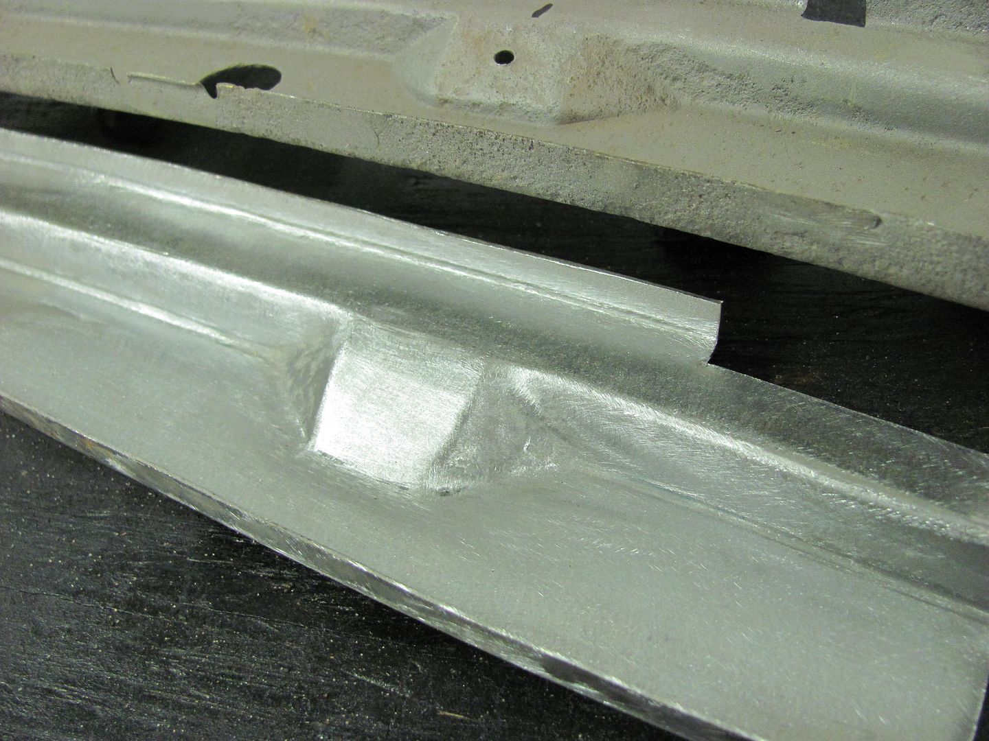
Took a few passes, but worked real nice. Now for a relief cut and a weld...


Picture240.jpg


Picture241.jpg


Picture242.jpg


Picture243.jpg


Picture246.jpg


Picture247.jpg


Picture248.jpg


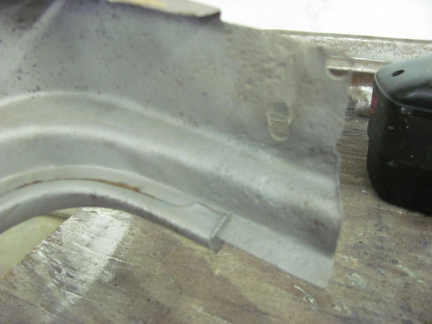
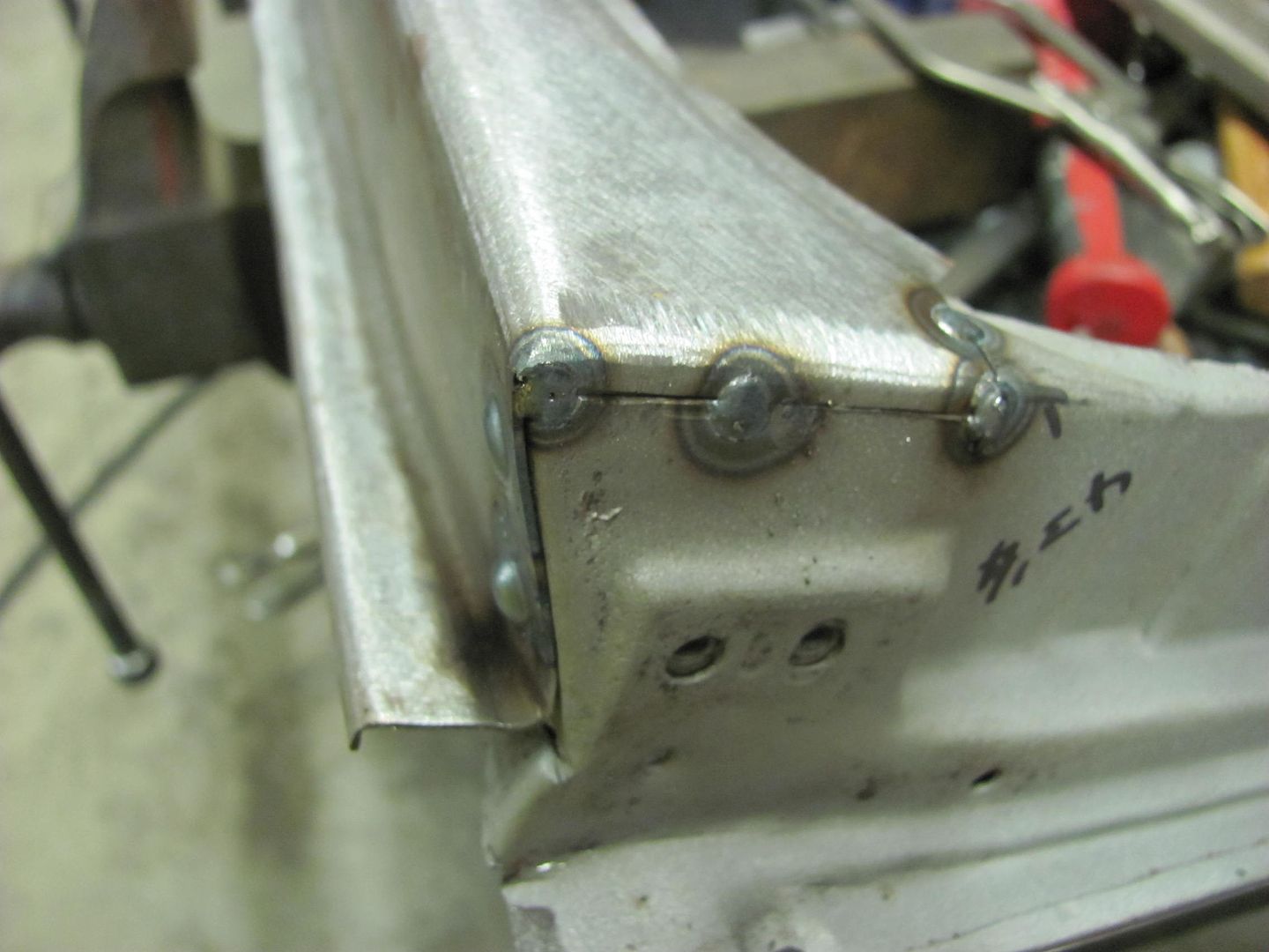
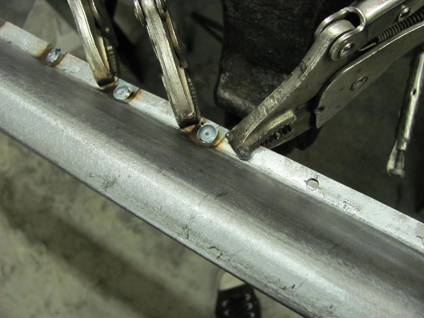
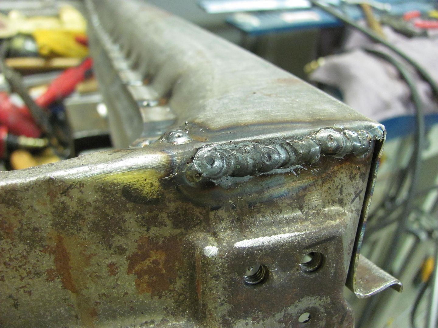
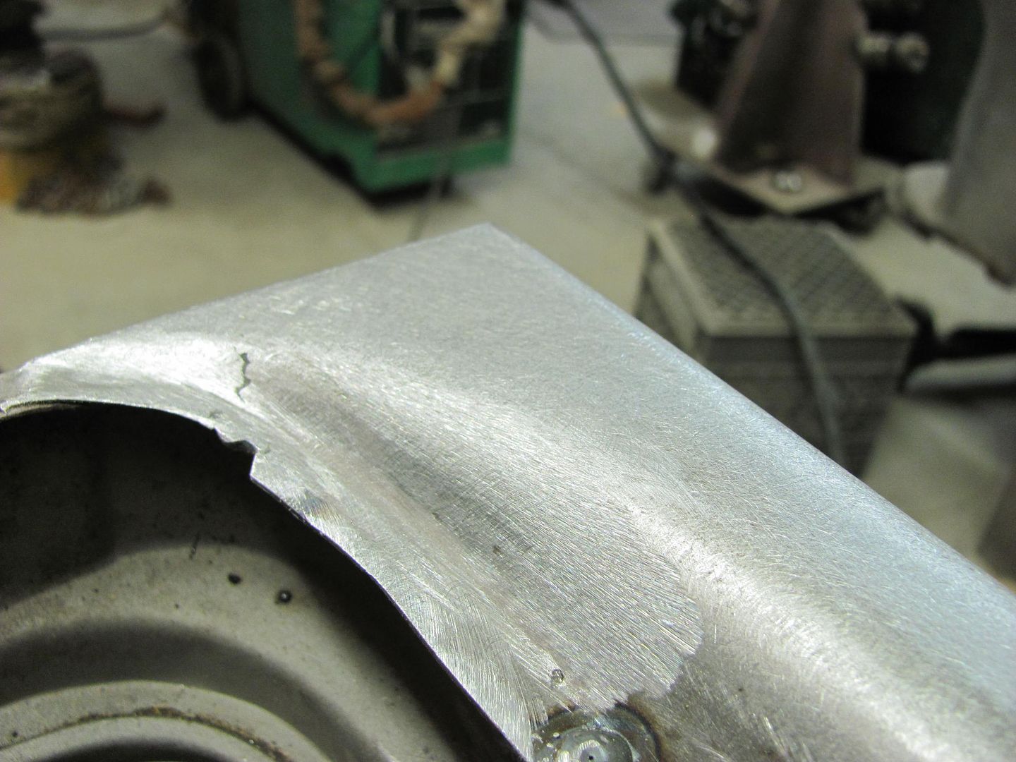
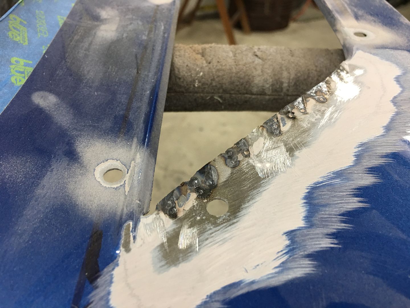
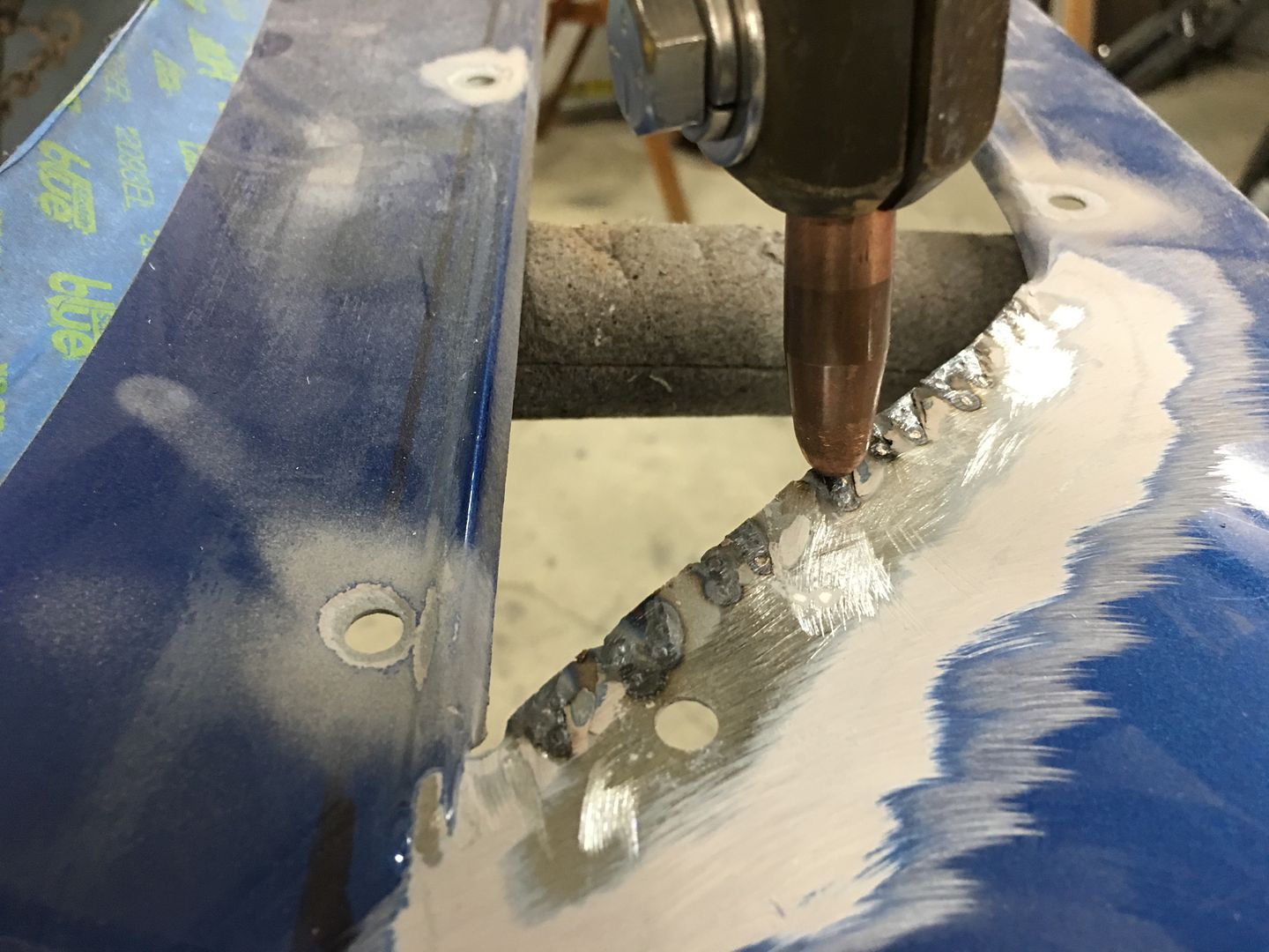
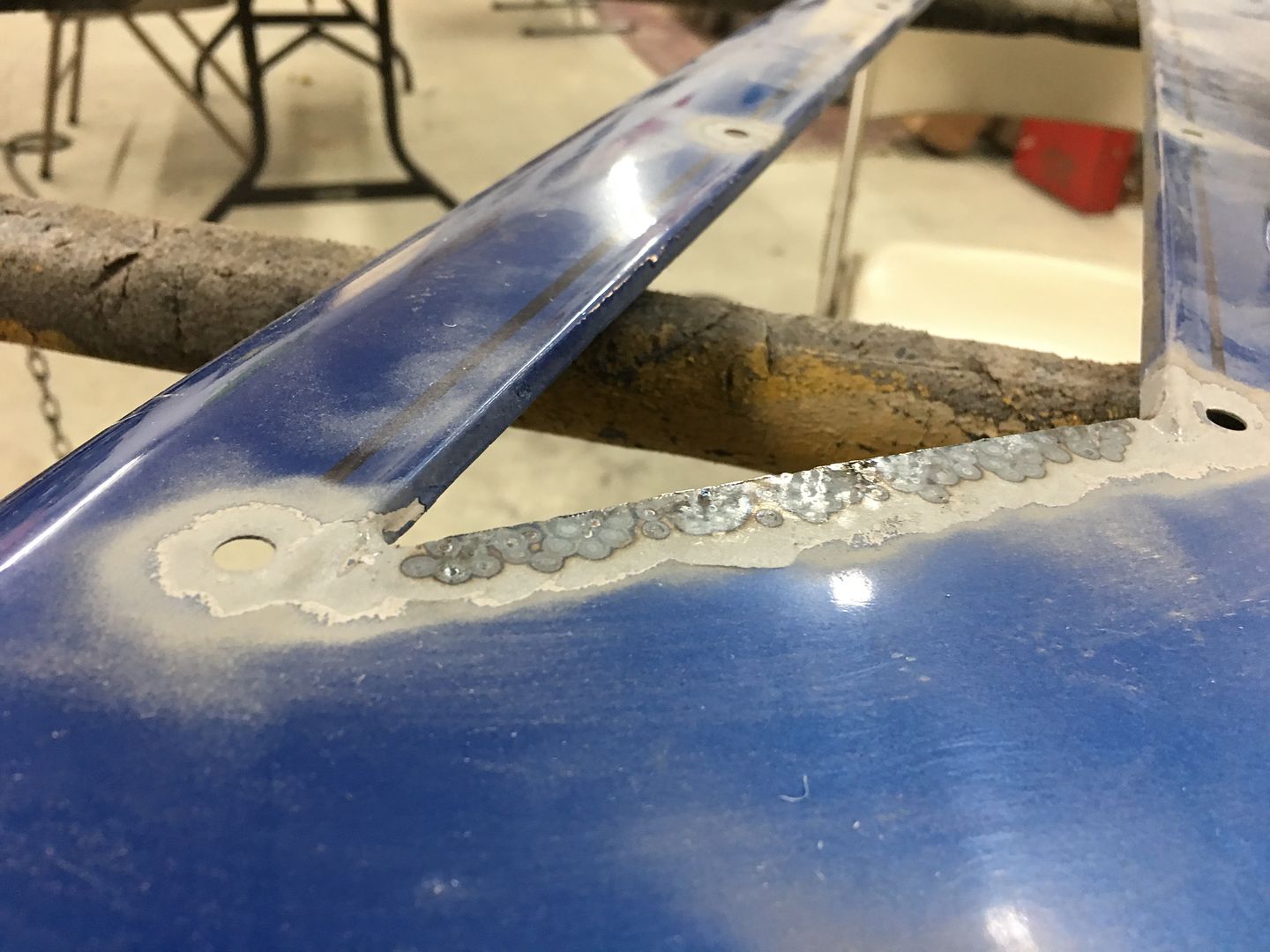
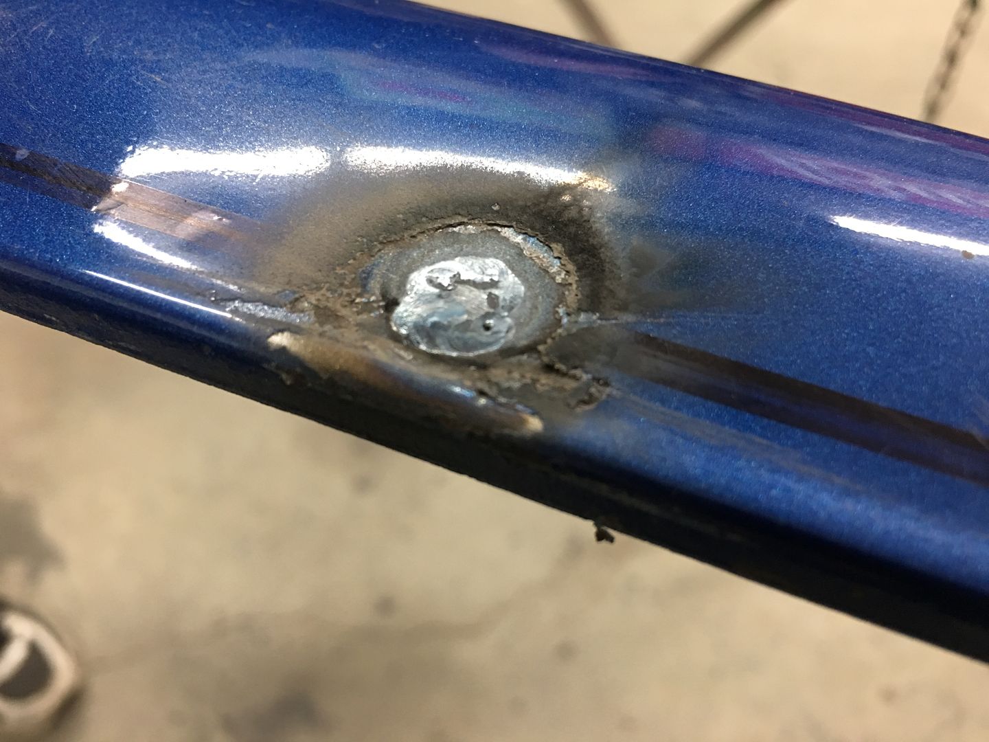
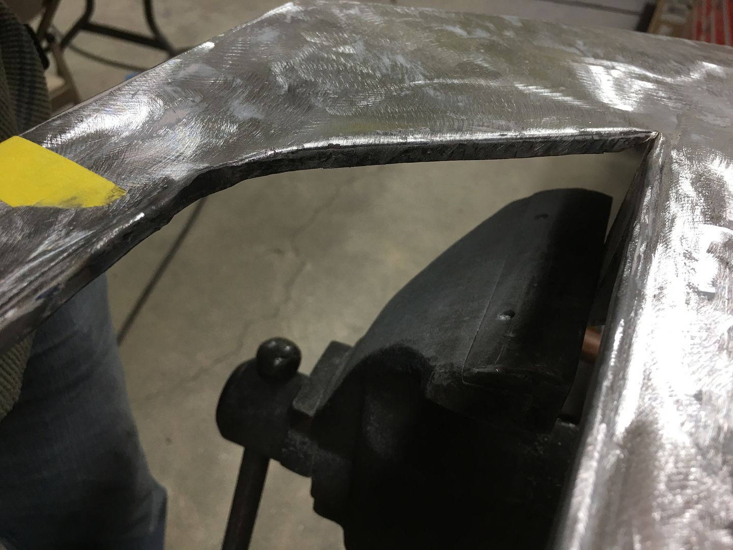
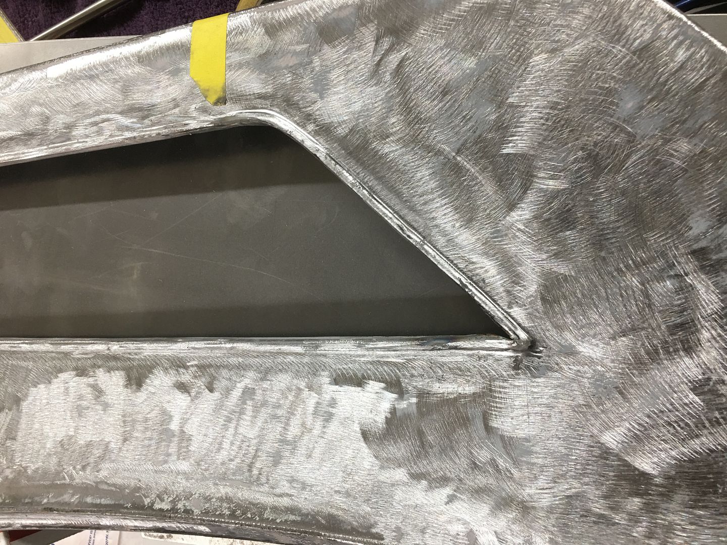
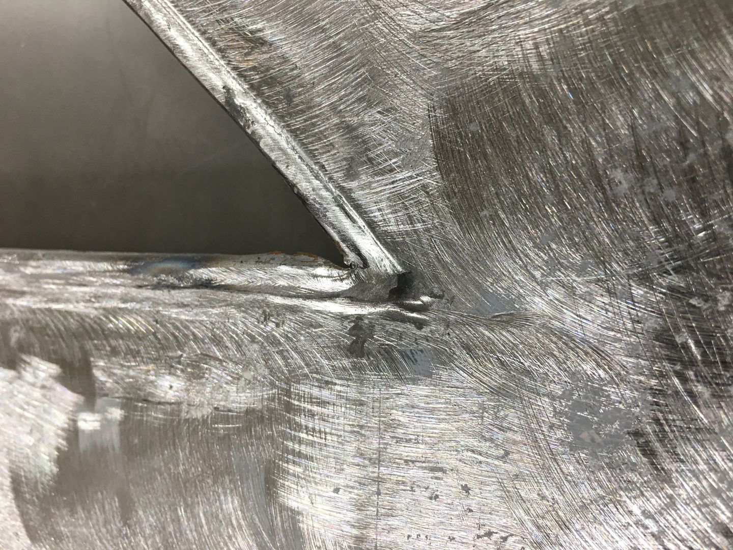
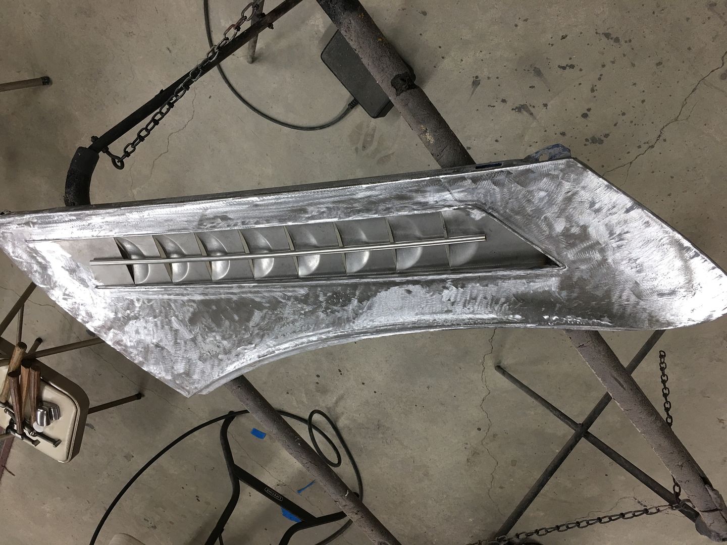
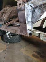
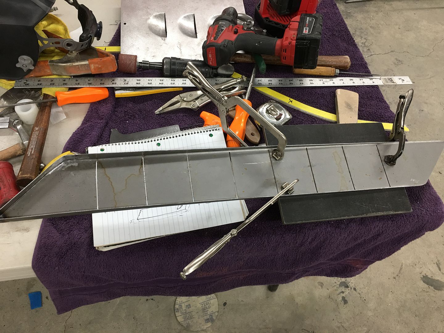
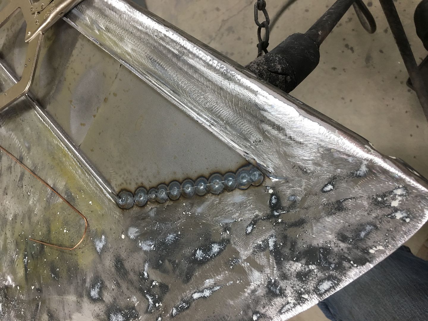
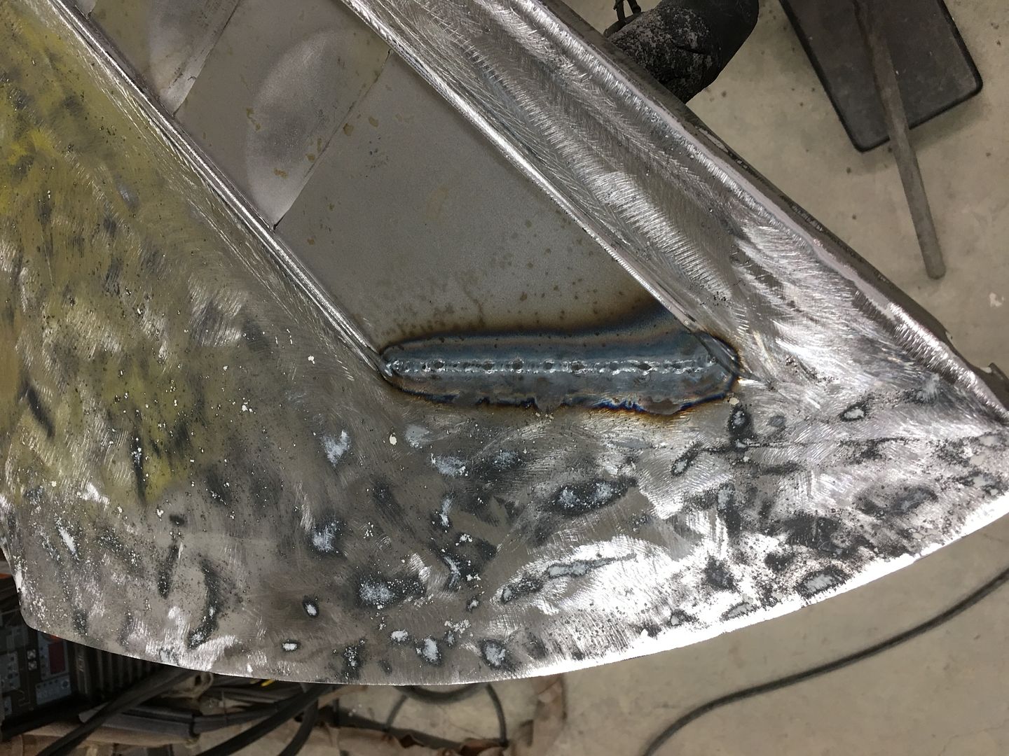
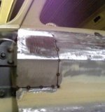
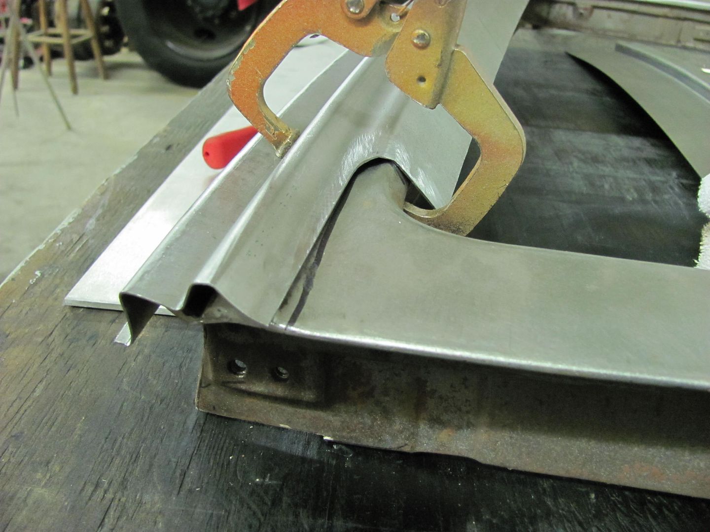
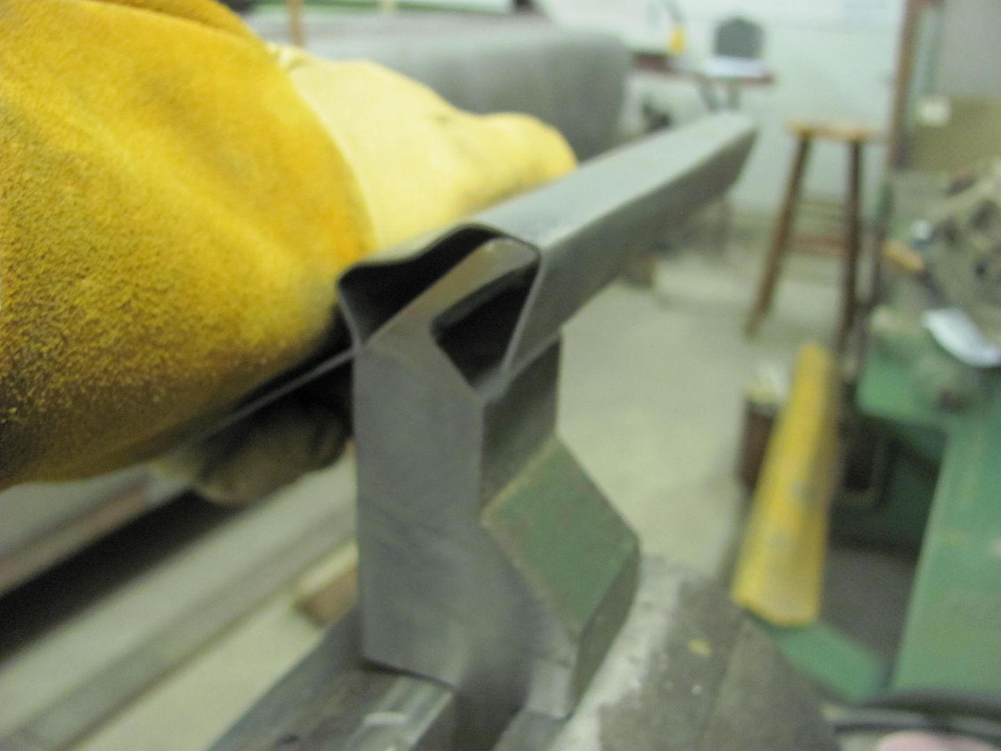
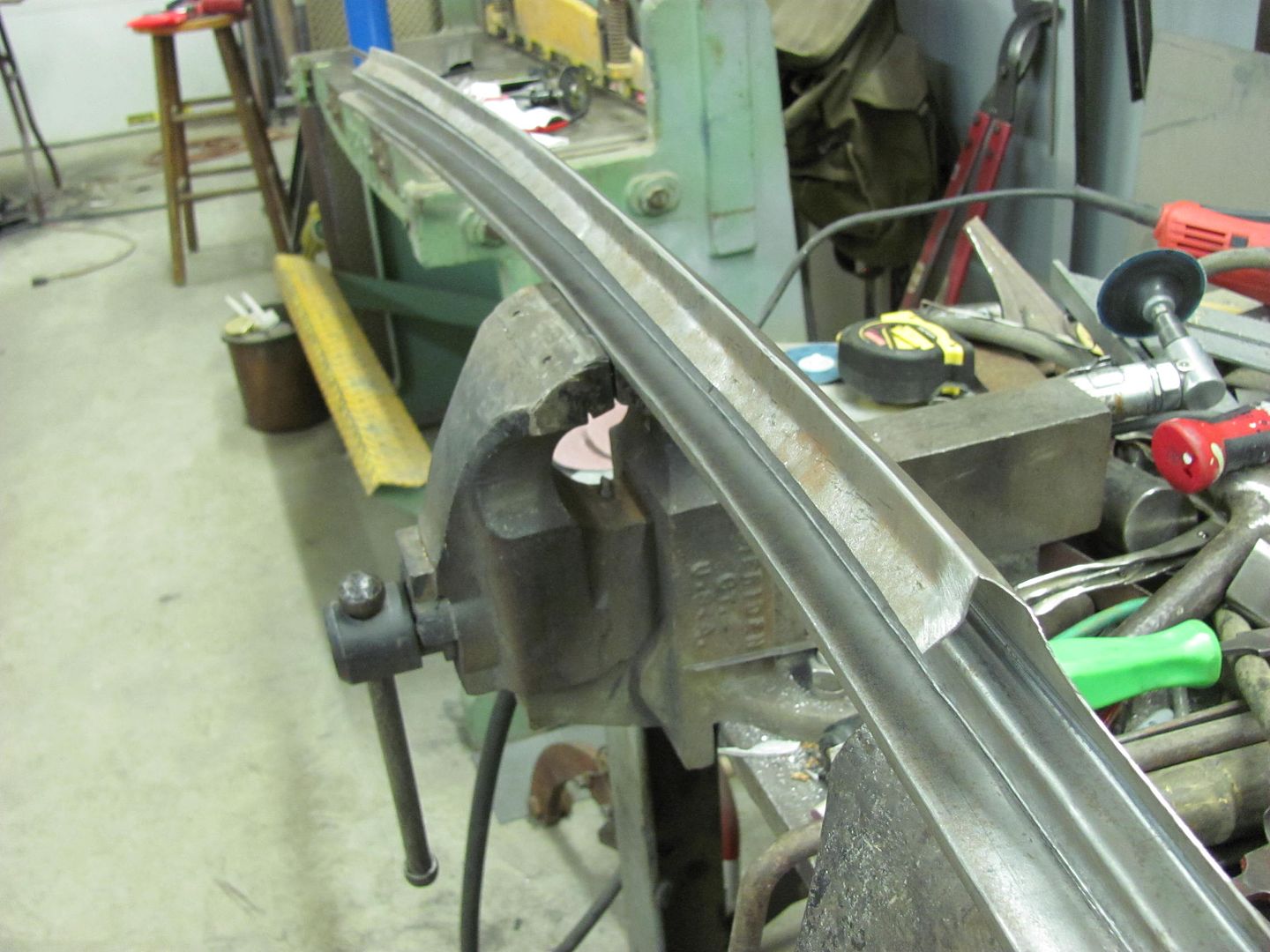
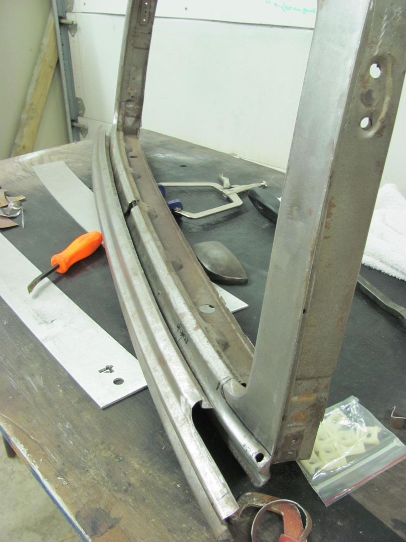
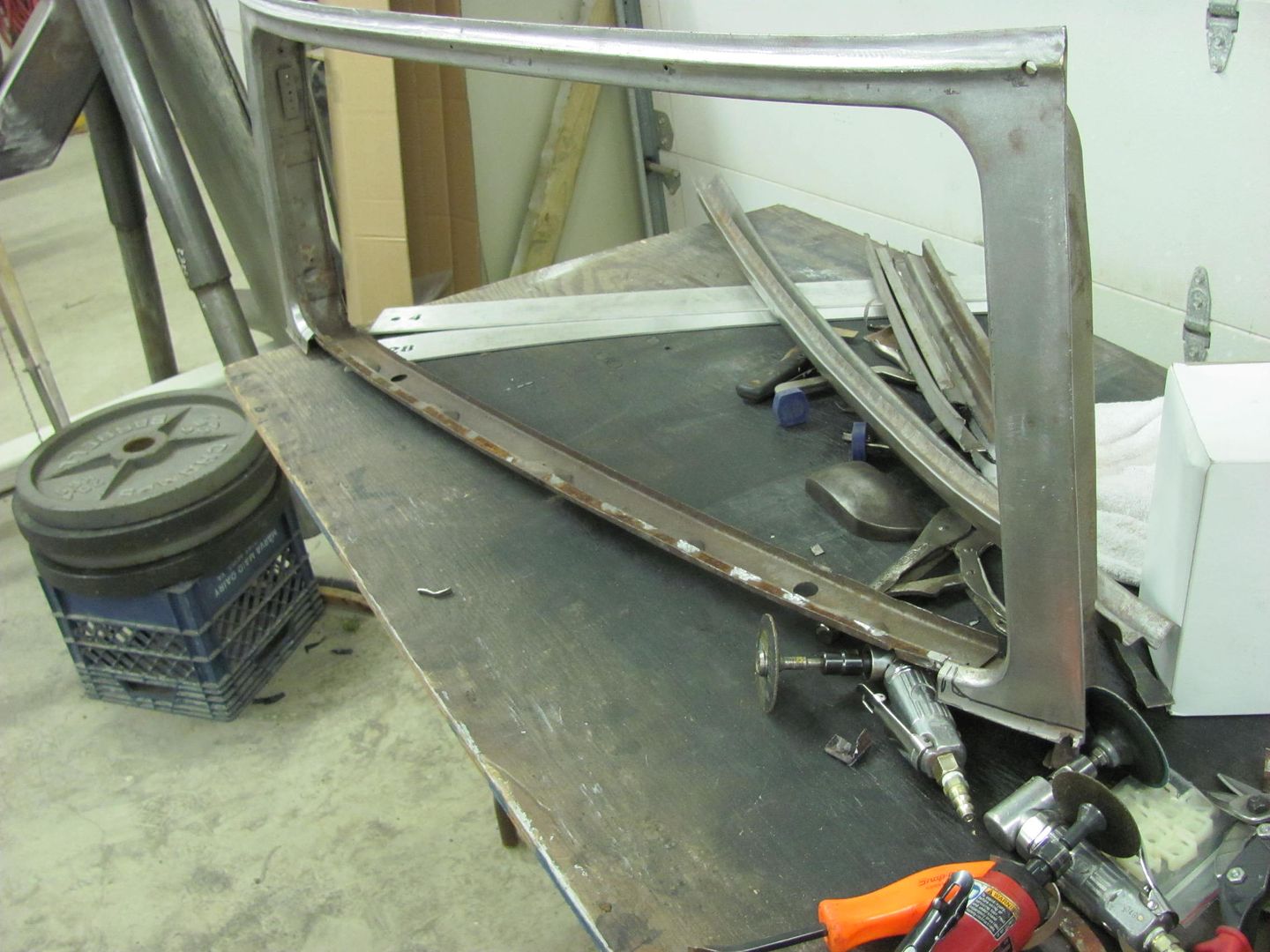
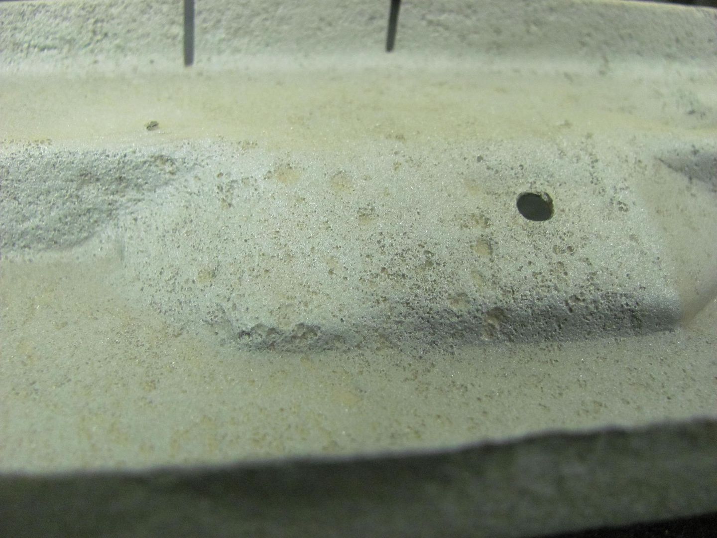
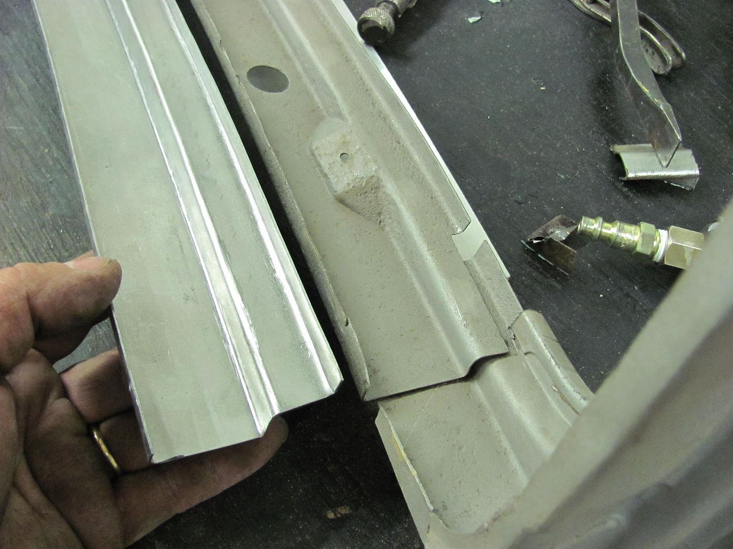
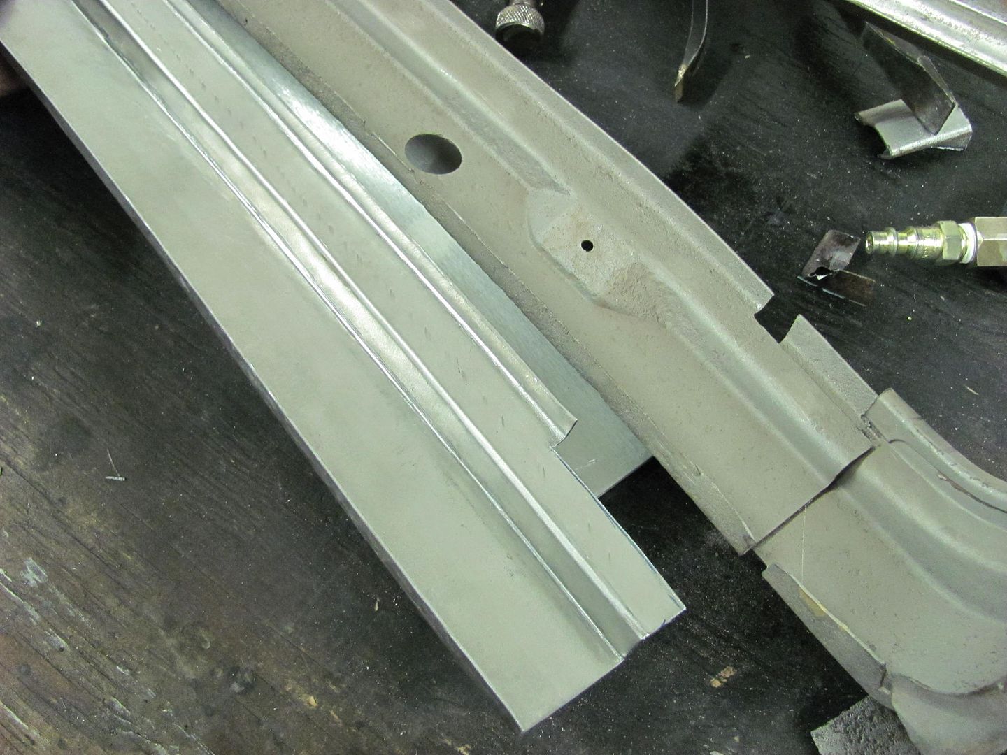
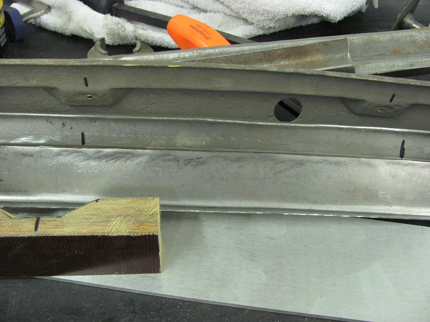
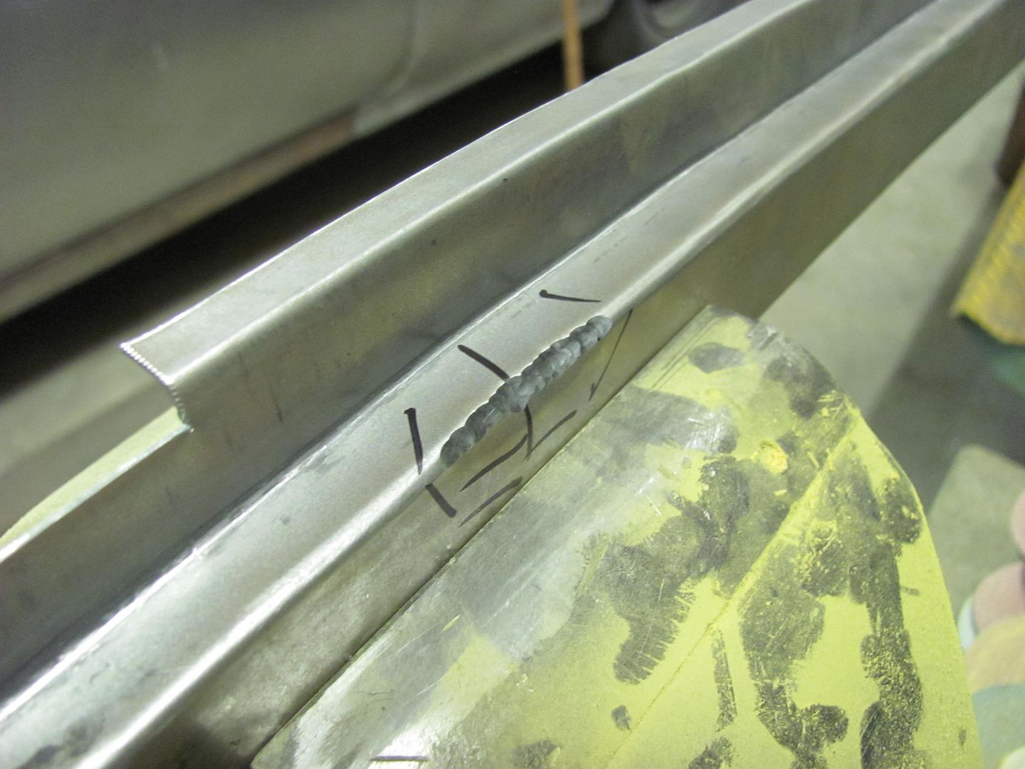
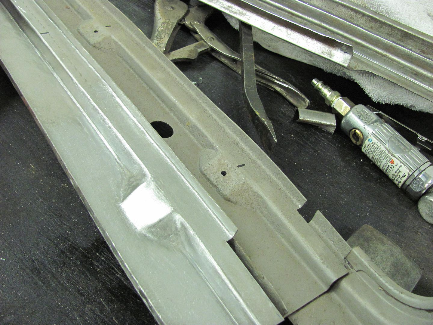
Rust hole removed, patch trimmed and fitted, then welded in place..


Picture252.jpg


Picture253.jpg


Picture255.jpg


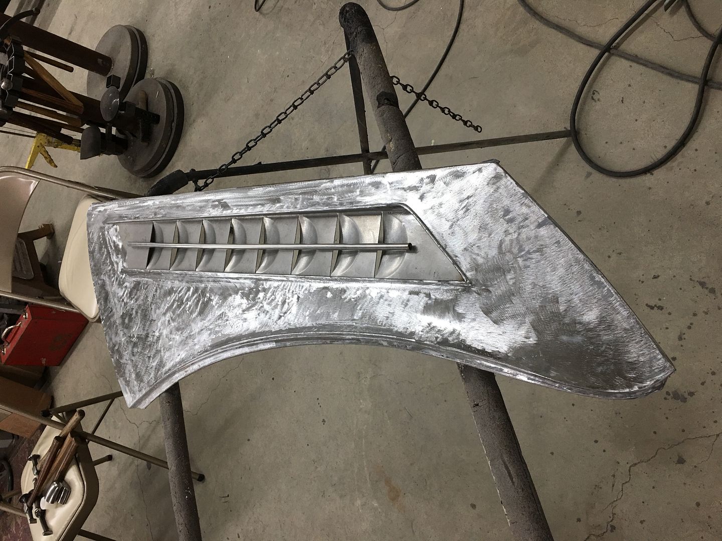
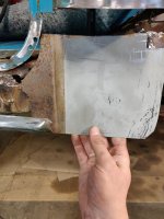
.....and Paul cleans it up for paint..


Picture257.jpg


You never know what you see over here... :lol_hitti
 
To avoid these ads, REGISTER NOW!

Shortbed70

Member
Joined
Mar 23, 2013
Messages
21
Location
Kansas...
Here's one I've done on my truck... Made with a ball peen hammer, flat tip screw driver w/no handle and concrete floor, block of wood. I laid out a grid on my two contours and pounded on the lines back and forth up and down until I had my rough shape. Then took the screw driver blade and used as a blunt chisel to create my seam. The finished it on the block of wood to get all te dimples out...
 

Attachments

  • image.jpg
    image.jpg
    33.1 KB · Views: 257

MP&C

Well-known member
Joined
Oct 21, 2009
Messages
4,403
Location
Leonardtown, MD
Nice patch job!

So, just how long will a D5 Cat run without oil? lol


I think the clay packs in tightly enough that it holds it for awhile. When he notices a drop in the oil level, its time to check on things... :lol_hitti


Time to give this thread a bump!


Next on the list for the wagon, the upper gate. It has a similar stance as the lower gate when closed, and as such, water lays along the inner window frame at the bottom.


Picture375.jpg


Picture376.jpg


Ice pick test....


Picture378.jpg


The lower bend is fairly flat, going to a tipped flange in the form of an arc, the inside has some compound curves going to the window opening flange...


Picture379.jpg


Picture380.jpg


Picture381.jpg


Picture382.jpg


This gets cut out and formed in one piece, flange to flange, for a easier job of replacing..


Picture383.jpg


My tool of choice for removing spot welds is a 3" x 1/16 cutoff wheel. I also use the premium wheels made for stainless steel. It's worth the extra money when you don't have a brown cloud in the shop, like the el cheapo wheels leave, nothing but resin wearing away.

The upper layer of metal will start to turn blue when it gets thin and hot, letting you know you're getting close to the next layer. When you have a blue circle with shiny metal in the center, you are now in the second layer, grind around the blue a bit more and pry the layers apart..


Picture385.jpg


With all the spot welds removed, here's what we find inside...


Picture386.jpg


Picture388.jpg


Picture389.jpg


Note the deep pits. The big problem with just welding a hole closed is you don't know where the next pit is lurking, ready to break through your new paint.


Picture391.jpg


Funny, with all the rust and scale inside, then you find this area of bare steel nice and shiney..


Picture387.jpg


The inside will get media blasted to insure there is no more lurking issues and then epoxy primered before re-assembly.


Here's a better look at the shape we'll need...


Picture392.jpg


Picture393.jpg
 
Last edited:

MP&C

Well-known member
Joined
Oct 21, 2009
Messages
4,403
Location
Leonardtown, MD
To start the layout on the new metal, I wanted to find the center of the radius along the window opening. By holding a sanding disc on the flats and scuffing, it showed the edges of the radius...


Picture396.jpg


Picture397.jpg


Picture398.jpg


Then laid out a pattern to be able to measure from the bottom crease...


Picture400.jpg


....and transposed it to the new sheet...


Picture401.jpg


Picture403.jpg


Picture404.jpg


The top edge was trimmed to size and the tipping wheel used to fold over the welding flange...


Picture405.jpg


Picture407.jpg


Comparison....


Picture409.jpg


The bottom was marked with the tipping wheel and folded in the apron brake. Then trimmed to size, again using the tipping wheel to fold over the welding flange...


Picture410.jpg


It's real close right now, just needs a bit of tweaking.


Picture412.jpg


Picture413.jpg


Picture414.jpg


Picture415.jpg


Picture416.jpg


Picture417.jpg


My 11 year old Vanna White also helped fabricate the repair piece in providing the rotational force for the bead roller. One of these days I need to add an electric option to bead roller, but in the meantime, it does get my daughter out in the shop :lol:
 
Last edited:

1969

Well-known member
Joined
Jan 8, 2010
Messages
1,412
Location
East Coast
How one man can be so talented and others that can't walk and chew gum at the same time is beyond me!
 

superspec

Well-known member
Joined
Nov 28, 2011
Messages
2,172
Location
WM louisiana
so that was your first time doing that right?

I need to work on slowing down long enough to create a plan of attack.
 

MP&C

Well-known member
Joined
Oct 21, 2009
Messages
4,403
Location
Leonardtown, MD
About the most complex pieces I had made thus far on the bead roller were this windshield panel....


Picture089.jpg


Picture097.jpg


Picture107.jpg


....and these gauge pods...


Picture067.jpg


Picture070.jpg


Picture088.jpg


Picture093.jpg


Picture079.jpg


After doing these, I guess I felt more comfortable that my "hunches" on how to form the panel for the lift gate would work. What you see on that liftgate repair panel was the fabrication from the first time out. Sometimes a bit of luck is on your side. I think that's to make up for all the rust I tend to find, where the luck seems to elude me....
 

MP&C

Well-known member
Joined
Oct 21, 2009
Messages
4,403
Location
Leonardtown, MD
Time to bump this thread again.

Media blasted the inside of the upper gate to clean it up before welding the new part on. Unfortunately this revealed more in the way of pits, through holes, etc., so it now looks like more fabrication....

Picture419.jpg

Time to attempt some dies for the Lennox. Tonight's choice is some 1" thick phenolic sheet...

Picture077-2.jpg

Here's the profile we're looking for...

Picture079-2.jpg

The dies installed in the holders....

Picture080-2.jpg

Picture081-2.jpg

An offset bend was added to the sample 19ga in the brake, then the first of three passes.....

Picture083-2.jpg

Final pass.....

Picture084-2.jpg

Dies held up well....

Picture085-2.jpg

Picture087-2.jpg

Safety tip of the day, 3" roloc discs do a good job of shaping phenolic, so skin is no match.... (note thumb in above pic)

Where my "test sample" was made initially with straight bends in the brake, the actual piece on the lift gate is not straight, so the bends on the "good" piece will need to be bent using the tipping wheel.

Picture090-2.jpg

Picture089-2.jpg

The profile needs just a bit of tweaking, and I may try using a piece of metal inserted in a band saw blade cut to sharpen up some of the details.

Picture091-2.jpg
 

MP&C

Well-known member
Joined
Oct 21, 2009
Messages
4,403
Location
Leonardtown, MD
Checked the lower profile of the upper gate with radius sweeps to lay out the new piece...

Picture125-2.jpg


Picture126-2.jpg


Picture127-2.jpg


Laying out the pattern on 19ga steel....

Picture128-2.jpg


Picture129-1.jpg


Tipping wheel in the bead roller...

Picture130-2.jpg


......and a newly modified back stop, much better than the flat one.....

Picture131-2.jpg


Offset added with the tipping wheel......

Picture132-2.jpg


Then run through the Lennox.....

Picture081-2.jpg


Picture084-2.jpg


More tipping, then the step die used in place of skateboard wheel with the tipping wheel for the lower 1/4" fold...

Picture134-2.jpg


Picture136-2.jpg


Picture137-2.jpg


Next, need to fold the top in the window opening...
 

MP&C

Well-known member
Joined
Oct 21, 2009
Messages
4,403
Location
Leonardtown, MD
In order to generate less scrap metal out of what looks to be a good piece so far, I made a small sample to test the fold of the window opening. Beginning with using the bead roller tipping wheel....

Picture139-2.jpg


Picture140-2.jpg


This is about as far as it would go, and with the good piece already having bends at the bottom, would be a bit less once tried on that piece. This will require a custom made "anvil" for some hammer action...
The donor:

Picture142-2.jpg


As modified:

Picture143-2.jpg


Picture144-2.jpg


Picture145-2.jpg


Picture146-2.jpg


.....then for some manual tipping...

Picture147-2.jpg


Picture148-2.jpg


Picture149-2.jpg


Comparison to the original....

Picture150-2.jpg


Picture151-2.jpg


This looks close, next task will be to cut a sample out of the original and see how close we actually are in our bends.....
 

MP&C

Well-known member
Joined
Oct 21, 2009
Messages
4,403
Location
Leonardtown, MD
OK, enough of the practice pieces, time to finish the rest of the bends. Just to make sure we don't need any "tweaking", I'll cut a profile sample out of the center. This spot weld one the inner flange is far enough away so I won't need to grind out a spot weld, and still have enough of that flange for a good measurement. In other words, removed with minimal effort where it still holds it's shape accurately.

Picture152-2.jpg


Picture153-2.jpg


Picture154-2.jpg


Our profile template:

Picture155-2.jpg


Just to compare to our test sample, looks like the inner flange was bent down a bit much in the manual hammering, will have to ease up a bit...

Picture157-2.jpg


Outside profile looks good enough to leave alone!

Picture158-2.jpg


Following the measurement used on the test sample, the panel is run through the bead roller's tipping wheel nice and slow to give us an initial mark for the bend, then repeated to tip the flange downward...

Picture159-2.jpg


Picture160-2.jpg


This looks about all we'll get without distorting and pulling, so then it's off to the custom anvil...

Picture162-2.jpg


Picture163-2.jpg


Picture164-2.jpg


Picture165-2.jpg


Then for some manual tipping...

Picture168-2.jpg


Picture169-2.jpg


...and comparing to our profile sample......

Picture172-2.jpg


Ready to cut off the old next time...

Picture174-2.jpg


Picture175-2.jpg
 

MP&C

Well-known member
Joined
Oct 21, 2009
Messages
4,403
Location
Leonardtown, MD
The next task is to remove the bottom detail of the lift gate and sandblast the remaining structure in prep for epoxy primer. The lower edge did have a flange folded up, so a slit was cut along the edge and the door skin vise grips were put to use...

Picture177-2.jpg


Picture178-2.jpg


Picture179-2.jpg


Next, the spot welds inside were ground out.....

Picture180-2.jpg


Picture182-2.jpg


Picture183-2.jpg


Media blasting..... nice to finally see through the glass!

Picture184-2.jpg


The media blasting revealed a few more holes, and numerous pits, many of them close to breaking through.

Picture185-2.jpg


Picture186-2.jpg


Picture188-2.jpg


With all the other new metal going in the bottom, there's only one thing to do. Using the tipping wheel..........

Picture189-2.jpg


Picture191-2.jpg


Picture193-2.jpg


Picture194-1.jpg


Comparing to the pitted version.....

Picture195-1.jpg


Picture197-1.jpg


Picture198-1.jpg


Picture199-1.jpg


Picture201-1.jpg


Picture202-1.jpg


Next we'll need to do some corking to add the trim hole pad details.
 

MP&C

Well-known member
Joined
Oct 21, 2009
Messages
4,403
Location
Leonardtown, MD
Now to address the mounting pads for the window molding....

Here's the new "anvil", made from some phenolic sheet.....

Picture207-1.jpg


Picture208-1.jpg


Put an alignment mark on the anvil, fitted it to the originals, and added the mark there as well. Then transposed those marks to the new piece...

Picture209-1.jpg


Picture210-1.jpg


Anvil was located, and clamped in the vise to hold it's location

Picture211-1.jpg


Picture213-1.jpg


Started with the barrel end hammer.....

Picture216-1.jpg


Picture217-1.jpg


Picture218-1.jpg


Picture219-1.jpg


For the ends, I used a rounded tip chisel....

Picture220-1.jpg


Picture221-1.jpg


....and then another "anvil" to clean up the hammer marks a bit...

Picture222-1.jpg


Picture223-1.jpg


Picture224-1.jpg


Here's all the tools used....

Picture225-1.jpg


Touched up a bit with a sanding disc, looks close enough.... One down, 4 to go...

Picture226-1.jpg


Picture228.jpg
 

MP&C

Well-known member
Joined
Oct 21, 2009
Messages
4,403
Location
Leonardtown, MD
Working to finish up the pad details on the inner structure of the lift gate.... The center one was wider, so I used the same phenolic and just added a wider detail to the opposite side. I missed showing this earlier, but a handy-dandy battery saw works well to remove the bulk of the material, sawing parallel cuts and then just working the saw side to side to clear out the remaining....

Picture235-1.jpg


Picture236-1.jpg


Once cut out, the sanding disc is used to cut down the angled sides and touch up the bottom..

Picture237-1.jpg


This compares the two, showing the difference in width...

Picture238-1.jpg


Picture239-1.jpg


Alignment marks transposed from the original, and guide marks indicate the area in need of hammering...

Picture242-1.jpg


Picture243-1.jpg


I had a request to show the hammering procedure, so here's another video attempt. The first one is using the phenolic anvil clamped against the work piece in the vise, the second uses 1" square stock as an anvil to clean up the hammer marks a bit...

http://s5.photobucket.com/user/rmcc...y Wagon Restoration Album 3/Video232.mp4.html

http://s5.photobucket.com/user/rmcc...y Wagon Restoration Album 3/Video233.mp4.html

...also sounds like I have a loose hammer handle, something for another day.... ;)

Then the sanding disc was used for final cleanup. Here's the finished piece, just needs a couple holes drilled....

Picture245-1.jpg


Picture246-1.jpg
 

MP&C

Well-known member
Joined
Oct 21, 2009
Messages
4,403
Location
Leonardtown, MD
Continuing, the spot welds in the bottom piece were drilled out. This revealed a couple more pits, which were media blasted and MIG welded.

Picture253-1.jpg


Picture254-1.jpg


Picture255-1.jpg


All cleaned up, the new piece is plug welded on....

Picture256-1.jpg


Picture257-1.jpg


Then the inner panel is fitted up and tacked in place....

Picture258-1.jpg


Picture259-1.jpg


Picture261-1.jpg


Top flange clamped to check the fit.....

Picture262-1.jpg


Picture263-1.jpg


Finishing up the welding of the inner bottom panel....used a 3/16 hole for the plug welds this time. I normally use a letter A, but the flange here is a bit narrow, so a smaller hole it is. To make up for it the heat on the welder was cranked up a bit to insure a good weld.

Picture265-1.jpg


Picture266-1.jpg


Looking at the back side, these should hold well.

Picture267-1.jpg


All the plug welds done, then on to the corner seams.....

Picture272.jpg


Picture273.jpg


and after cleaning up the welds.....

Picture275-1.jpg


Picture277-1.jpg


Picture278-1.jpg


Picture279-1.jpg


Picture280-1.jpg


Then we'll clean up the plug welds on the flange, media blast the inside for good paint adhesion and some epoxy primer before closing it up..
 
Last edited:

Kevin54

MEMBER EMERITUS
Joined
Jan 12, 2005
Messages
29,341
Location
Urbana, Ohio
I swear, what you do is not work, it more art than anything!!!!

BTW.....I don't know if you hear it when doing it, but that Barrel Hammer has a hell of a ring to it. Even the dog turned his head when he heard it. :lol:
 

MP&C

Well-known member
Joined
Oct 21, 2009
Messages
4,403
Location
Leonardtown, MD
Yeah, it's one that I didn't change out the handle because it was so nice. I'll try again to tighten it up, but I do have a couple spare SO handles if it doesn't cooperate!
 
To avoid these ads, REGISTER NOW!

coma13

Well-known member
Joined
Nov 5, 2012
Messages
247
I built this beauty this weekend. The receiver is sheet metal that required a fair bit of bending, welding, heat treating and tweaking to get totally dialed in.

hyba9ynu.jpg
 

Kevin54

MEMBER EMERITUS
Joined
Jan 12, 2005
Messages
29,341
Location
Urbana, Ohio
Yeah, it's one that I didn't change out the handle because it was so nice. I'll try again to tighten it up, but I do have a couple spare SO handles if it doesn't cooperate!

Put a piece of foam rubber or take a grommet, split it, and put it around the handle and it should stop ringing. Although I imagine that on your end, it's probably not noticeable.

A lot of times turning something on the lathe that has a thin wall will just scream along with getting a lot of chatter. I watched guys at work change speeds and feeds trying to get rid of it. All I have to do is take a paper towel, shove it into the bore, and it will take all the squealing away. :lol:
 

MP&C

Well-known member
Joined
Oct 21, 2009
Messages
4,403
Location
Leonardtown, MD
Been a while that we've seen Jim's sheet metal thread pop up. Let me add some content to give it a bump..


Had a couple hood sides for a 37 Ford show up at the shop recently. The owner wanted to remove the side "grille", and add a tapered recess pan with clamshell louvers. Here's what we started with...


IMG_4192.jpg


Some cutoff wheel action later....


IMG_4195.jpg


In an attempt to keep as much metal on the ends as possible, we opted to flatten the sad remains of the horizontal fins. This involved some shrinking via the heating tip in the dent puller..


IMG_4199.jpg


IMG_4200.jpg


Looks like someone has spilled bondo all over this panel. Funny the inside didn't look all that mangled to warrant the amount we found.. Must be a TV car..


The shrinking efforts flattened out the ends fairly well...


IMG_4201.jpg


IMG_4202.jpg


I filled in the previous trim holes with 18 Ga plugs and TIG fusion while the owner worked away at removing the bondo so we could see what we had to work with...


IMG_4207.jpg


IMG_4208.jpg


IMG_4209.jpg


IMG_4211.jpg


Next, we had to fold a flange in the front and extend the factory bead around the opening down the front where we had flattened the panel. Some of the existing bead profiles had seen better days in the past 80 plus years, so I checked a set of joggle dies I had made for drip rail as it looked close...


IMG_4213.jpg


IMG_4214.jpg


New flange folded at the front, bead added using the Lennox, original beads touched up ...


IMG_4219.jpg


IMG_4223.jpg


IMG_4222.jpg


Tapered pan fabricated.....


IMG_4226.jpg


Louver layout


IMG_4228.jpg


IMG_4229.jpg


Welded in place..


IMG_4230.jpg


He is having some art deco style trim pieces made to accent the louvers down the center, topped by 62 Impala fender trim. We didn't have those, so here it is with alternate SS fuel line for your viewing pleasure...


IMG_4232.jpg


IMG_4234.jpg


IMG_4235.jpg
 

speed bump

Well-known member
Joined
May 28, 2008
Messages
6,317
Location
Butte Montana
While not nearly to the level of MP&C this repair wouldn't even be close to as good as it was without all of the information he has shared over the years.

Decided to deal with my 71 F250s bad cab mounts this winter. Along the way I figured I should also do something about the cab corner.
attachment.php


So I cut out pretty much everything until I had some decent sheet metal.
attachment.php


Then started making some new pieces. For the sill plate where it tapered down I figured a buck would be the easiest way to form it.
attachment.php


After probably 2 hours of work I had a piece that fit pretty well
attachment.php


Then I cut the piece to repair the kick panel, insanely it was 90+ percent correct from the get go and only took about an hour to make.
attachment.php


Then I decided to make the pillar in roughly two pieces so I started forming the front of the pillar. Keeping with motto everything is a tool this piece of conduit seemed to match radius I needed for the corner pretty well.
attachment.php


At this point I smeared most of the parts I wouldn't be able to access anymore with epoxy and started burning it in. This is where I left it last week when I had to go back to work.
attachment.php


Overall I probably have 60 hrs into this corner but it had been a good learning experience, mostly in the motto of buy the best thing you can to start with. :lol_hitti
 

Attachments

  • IMG_20190101_190056.jpg
    IMG_20190101_190056.jpg
    101.1 KB · Views: 786
  • IMG_20190101_141838.jpg
    IMG_20190101_141838.jpg
    90.9 KB · Views: 786
  • IMG_20181230_152621.jpg
    IMG_20181230_152621.jpg
    101.2 KB · Views: 812
  • IMG_20190214_153300.jpg
    IMG_20190214_153300.jpg
    100.9 KB · Views: 789
  • IMG_20190124_145252.jpg
    IMG_20190124_145252.jpg
    90.1 KB · Views: 783
  • IMG_20190102_151426.jpg
    IMG_20190102_151426.jpg
    95.3 KB · Views: 787
  • IMG_20190126_131152.jpg
    IMG_20190126_131152.jpg
    107.1 KB · Views: 788

MP&C

Well-known member
Joined
Oct 21, 2009
Messages
4,403
Location
Leonardtown, MD
That looks quite good, especially considering the improvised radius brake. Determination makes one hell of a tool.
 

Stooge

Well-known member
Joined
Mar 24, 2013
Messages
3,533
Location
South Shore, MA
Some of my cobblings, theres a lot more in my old and current thread but my computer is doing some updates and is being a pain to link pictures :confused:

2019-02-22_07-32-20 by Dan Haas, on Flickr

20150524_095212 by Dan Haas, on Flickr

2019-02-22_07-29-17 by Dan Haas, on Flickr

20181013_141210 by Dan Haas, on Flickr

20181209_121502 by Dan Haas, on Flickr

20181220_153525 by Dan Haas, on Flickr

20180622_170437 by Dan Haas, on Flickr

20180622_170712 by Dan Haas, on Flickr

20180916_111524 by Dan Haas, on Flickr
 

Stooge

Well-known member
Joined
Mar 24, 2013
Messages
3,533
Location
South Shore, MA
What did you use for stainless trim across the dash?

i bought some 1/2? tubing, used some line tape to mark off about a 1/3rd of the circumference, mickey mouse'd some fixturing together to hold it in place and very slowly used a cutting wheel on a die grinder to cut that portion out, then did it 2 or 3 more times for rest of the pieces and I think I screwed one of them up and had to do it over again. then used an industrial retaining compound to secure some button head screws to the backside of tubing, (round button head to follow the round tubing made the most sense to me) so I had a way of securing it to the dash. I like the look, but im sure there would have been a more efficient way of doing it.
 

MP&C

Well-known member
Joined
Oct 21, 2009
Messages
4,403
Location
Leonardtown, MD
Nice execution with minimal tools. I've not graduated to stainless trim fabrication yet, but it is on the list. For those on IG, this is about the slickest fabrication of trim that I've seen. Chris Davenport at Salt Flats Speed Shop is a sharp cookie!!


https://www.instagram.com/p/-WrYLir_Rm/


https://www.instagram.com/p/-WrzkVr_Sd/


https://www.instagram.com/p/-WsJbtr_TP/


https://www.instagram.com/p/-WsZo9L_T3/


https://www.instagram.com/p/-WspwRr_Ui/


https://www.instagram.com/p/-WtQTir_V6/


https://www.instagram.com/p/-WtjXLL_Wq/
 

jeepinerdeep

Well-known member
Joined
Dec 28, 2013
Messages
2,099
Location
South Central PA
You guys are something else with your wizardry in here. I'm just happy when I get a 90 degree bend in something without it looking like I mashed it over with a dull apprentice.
 

sberry

Banned
Joined
Jun 18, 2005
Messages
35,747
Location
Brethren, Michigan
Welding booth. All from scrap, washer and dryer including door hinges. The lid on the welder in the truck folds up and the machine can be extracted from the top.
 

Attachments

  • boot weld.jpg
    boot weld.jpg
    150.8 KB · Views: 62
  • booth front.JPG
    booth front.JPG
    51.1 KB · Views: 53
  • welder back.jpg
    welder back.jpg
    34.7 KB · Views: 56
  • welder covered.jpg
    welder covered.jpg
    33.4 KB · Views: 57
  • booth cab.jpg
    booth cab.jpg
    112.2 KB · Views: 59
  • booth front 1.JPG
    booth front 1.JPG
    60.7 KB · Views: 56

Bansheeboy11

Well-known member
Joined
Jul 15, 2014
Messages
103
Location
NY
Heres that under guard i made

Mocked up the under guard, going to cut it tomorrow and try to bend it in a siding brake so i hope its thin enough. Ill try the lift arm dimple die too. FYI a 4' by 3' sheet fits wheel to wheel, rad support to cross member with a little extra. This is .080 annealed/anodized aluminum.

vOCUeEw.jpg


LqbAHoz.jpg


So i tried the lift arm method, wasnt enough weight so i stood on it. That wasnt enough weight, so i threw all the heavy things in the garage on top. That wasnt enough, so i decided just to lower the whole car onto it, which worked like a charm.

Trimmed some corners a bit, bent the sides and front up, all thats left is some rivnuts for the rad support and a few dimple dies around the thing and its just about done.

UNR5Nl6.jpg


DupsKGB.jpg


Q70mQVy.jpg


K4hObS8.jpg


I3iC9S7.jpg


Theres about 5-6mm of gap from the pan, a little more at the crossmember. Should be enough space to keep it from rattling if it vibrates a bit.

HeMhtlS.jpg


I finished up the guard last night, it'd be really cool to have one water/laser cut for clean edges as this looks ok but not having even edges/corners bothers me. I threw a STI sticker on it to distract from one of the bends not being even. It works and doesnt rattle.

kQbamZH.jpg
 

MP&C

Well-known member
Joined
Oct 21, 2009
Messages
4,403
Location
Leonardtown, MD
Hood side number two completed yesterday. The flanges of the tapered pan get some stretch treatment in the kick Erco to match the profile of the hood side..


IMG_4283.jpg


For the questions about the cutting device, it is a long nose pneumatic cut off tool from Blue Point. For keeping the cut nice and perpendicular, and disc width, the long nose works better (for me anyhow) by having the long nose as a visual guide to keep it parallel to our centerline. I don't think I would have seen as good of results using the standard cut off tool.


IMG_4284.jpg


IMG_4285.jpg


Each slot has stop drill holes at the end, to help remove any cracking issue and also to better determine end of cut.


IMG_4287.jpg


IMG_4288.jpg


E helped out with the punching efforts...…


IMG_4289.jpg


IMG_4291.jpg


Panel gets tacked in and welded with the TIG...


IMG_4292.jpg


IMG_4293.jpg


IMG_4295.jpg
 
To avoid these ads, REGISTER NOW!
Top Bottom