(((Already posted this in my garage thread but weld projects belong here!)))
So had my first welding job today...
A friend asked me to weld one spot on his smoker that he is building... And I tried to talk him out of it, since I do not consider myself a welder.
I asked if it was aluminum? He said no. I said damn cause I can't weld aluminum. I asked if it was stainless steel? He said no. I said damn cause I can't weld stainless steel. I asked if it was thick metal? He said no. I said damn cause I don't have 220volts set up in my garage to weld the thick metal. I asked if it was really thin metal? He said no. I said damn cause I can't weld thin sheet metal I tend to burn through it.
So long story long I couldn't talk him out it and I ran out of excuses...
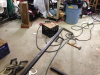
So he brought over several different thicknesses of metal that was from a bed frame and a weight bench; all different gauge steel and all powder coated and very thin stuff...
And I don't know the fist thing about smoking meat. No clue what temps this metal would heat up too or what is safe to eat off of and the big part how to build one. So I thought he would have a plan on how to build it maybe done some research online on some type of forum with a step by step process. Nope. He handed me some random scrap metal and said what did you think we should do? I said go buy one.. amazon has them pretty cheap. But after scratching my head starring at it for a while I realized I only had a few hours before the wife got home so better start tacking it together... It ended up extremely hard to weld cause the powder coating and different thickness of tube...
So after it was done it was extremely wobbly and I had some metal set aside for another project but I decided to cut it up to make extra support. I wanted to immediately scrape the first part and start over; we'll clean steel tubing and do it the right way but he said it was fine the way it was... I made him promise not to tell anyone that those weld beads were mine cause they were the worst I have done yet. It seemed impossible to get a good ground I should have stripped more paint off the tube for the placement of the clamp...
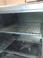
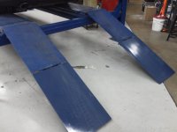
Here's what he brought over...
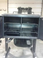
Had to beef it up...
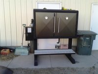
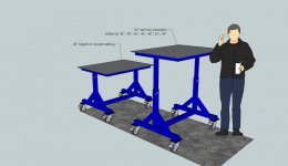
Well here's how it turned out...
Nooooo up close pics of the welds!


")