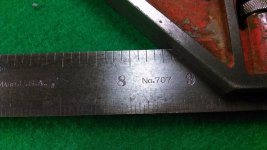
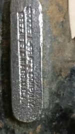
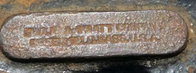
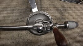
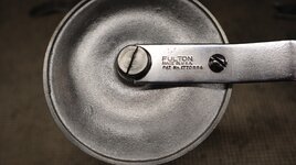
Goodell-Pratt 2510 Brace.

The OLDTOOLHEAVEN site (
Goodell-Pratt Bit Braces (oldtoolheaven.com) has information on this brace. Actually a very nice brace, the one I got though had problems. Rust (of course), but more of an issue was that both the chuck spindle and top handle did not rotate smoothly. Decided a full disassembly was needed.
Before I get into the disassembly, a few thoughts about why we collect. First, it’s something we enjoy. Finding a new version brings you joy. Second, we like to clean them up and help with the preservation. Third, we hope the value goes up. Fourth, and maybe the most important, is education. Not just for ourselves, but we hope others study the designs and learn something.
Going back to the second reason, preservation, this can take many forms. At a minimum, light scraping of rust and then some oil, maybe some wood finish. Then there are the “original” collectors, who insist that the preservation not disturb any original paint and all parts are correct. Patina must be original. To be honest, these are usually rare to find. Usually tools have been cleaned a little further than the original collectors would want. However, the tools still represent what the manufacturer made. Something I question is who is going to take care of or appreciate these tools in the future when we are gone? So now lets consider finish. Steel and iron, will rust, unless it is kept oiled or a protective coating applied. This coating many times was jappaning, a thick tar-like paint. Not easy to find or apply, but is correct for some restored tools. Modern enamel works, and is easier to find. It does not change the function of the tool. Then there is nickel-plating. Usually used on higher quality tools or for details, it is more durable than the other finishes. More expensive and more steps involved, but it adds a touch of quality to the tool.
Now the fourth reason, education, requires the preserver to determine how what they are doing will spark interest in the tool. Personally I feel that nickel-plated tools reinforce the idea that the tool is important to keep. Less likely to be put in the scrap bin because it looks valuable. We need to get the younger generations interested and maybe shiny tools will help.
With that thought, I decided to re-plate this brace. That meant the wood handles had to come off and a full disassembly. This is where experience and tools come into play. I know the wrist handles are slid onto the shaft before they are bent. There is no way to remove the handle the way it went on. Usually when I make this kind of decision, I come up with Plan A, B, C as needed. My plan A for the handle was to use a razor saw and make a couple cuts down the length of the handle, in the hope of glueing the pieces back together after the plating. My plan B is to make a new handle and put it together like on a Spofford brace, with pewter rings cast around them. Plan C, is to use a more modern approach and use a spiral external retaining ring. So far it looks like plan A will be tried first. If it doesn’t work, then on to the other plans.
Now anytime you are taking something apart this far, you risk damaging it, beyond repair. So read the following and then ask if you would be comfortable doing it. Not everyone has the skills or tools to do all that I am going to show. However, I think my showing what is typically hidden may provide information for someone in the future.
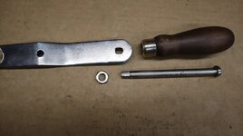
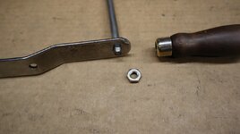
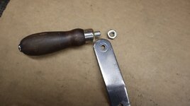
Starting with the wrist handle, I made several cuts, using a razor saw and a straight edge. Made several cuts. Note the collars retaining the handle have screws, to maintain the handle position. These can be moved outward, giving more room to cut the handle. There are also two brass rings that act as a bearing point for the collars. Being careful not to cut though the brass rings, I eventually was able to split the wood away from the frame. I was then able to clean that part of the frame.

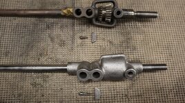
Next is the chuck. Like most, it simply unscrews, exposing the two spring loaded jaws. This was Loyd Millers patent. The jaws and springs pull out the end. Mine were tight on the springs and required some effort to pull out.

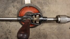
Removing the chuck spindle (Farley patent) required unscrewing the screw going through the selector ring. Under this ring is a thin steel washer with special holes. These holes line up over the two ratchet plates. Once the screw, selector ring and washer are removed, the spindle will slide out the end. (No loose parts). The spindle itself has two ratchet plates that are held by a small spring that wraps around the spindle in a groove. If needed, the spring can be carefully unhooked, and the plates removed. I tried putting the spindle back in without the ratchet plates and discovered some burrs on the spindle that made it feel rough. This was smoothed.


Next is the top handle. According to Randy’s site, this model has either roller or ball bearings in the hub. Taking the wood handle off (three wood screws), the hub felt very rough. If yours feels rough, I suggest soaking that end in a rust dissolver. Then put some oil on it. Hopefully it will spin freely. If not, then you might not be able to fix it. To do a proper nickel plate, I needed to remove the top handle bearings. I ground off some of the frame until I could pry the washer off. Now comes the tricky part. The washer sits on a shoulder. The shoulder on mine was deformed a little when the washer was staked on. So I needed to use a punch to help the shaft out. But wait, there are bearings in there. So I put a plastic bag over the end and then used the punch to move the shaft out of the hub. The bearings fell into the bag. On mine there are six roller bearings. To describe them like a car wheel, they are round in the rolling direction, but one side is flat, to go against the shaft, and the other side is rounded like a Baby Moon hubcap. This rounded side matches the inside diameter of the hub. Don’t lose these as replacements may be impossible to find (except in another Goodell brace with this type of bearing). Out of curiosity, I did try some ball bearings. The smallest I had were 3/32” and they felt tight. Would not recommend changing types of bearings.


My next steps are to further clean and polish, then nickel-plate. May be a while before I post pictures of the finished brace.