To avoid these ads, REGISTER NOW!

Siemens listed accessories don’t fit

sodaparis

Active member
Joined
Oct 4, 2023
Messages
26
First off I want say thanks to all who responded to my first post asking about the proper wire setup.

Also I’m not an electrician, I was a general contractor for 20 plus years and trying to do a clean and competent install.

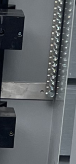
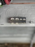
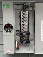
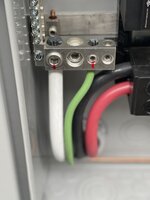
I pulled the wire in, and all went well, the most difficult part was the back to back LB’s through the garage wall. The issue I’m having is completely unexpected. I have contacted Siemens support to see if they have an option to complete this installation. The pictures show how I terminated the neutral using the manufacturer approved lug kit for the 4/0 neutral, torqued to spec and I thought, good to go. I then went to check the fit of the dead front and it contacts the neutral lug and holds the dead front out a 1/4” not allowing it to sit flush with the breakers. The bar on the right side of the panel sits on the back of the enclosure but it’s so tight to the side there’s no way to install the lug there.
I have a few ideas about how to resolve this and would like to see if anyone has come across this or has any ideas I haven’t thought of. It seems strange that lugs would be listed that don’t work anywhere. Even if I downsized the neutral the smaller lug kit still doesn’t clear.
Here’s my thoughts,
1) Attach a small Siemens bar on the left side drilled and tapped through the bonding strap identical to factory install of the bar on the right. And add the lug to that.
2) use a Siemens collar strap sized for 4/0, in the same location, that may move it back enough to clear the cover, it’ll be close.
3) there is a factory spot below the bottom breaker to add a ground bar, I could install that and add the lug and also add a jumper wire from there to one of the factory bars. The largest I could install is 4 awg for the jumper since the lugs don’t work lol.

Are any those options viable? Any other ideas?
I haven’t heard back from Siemens yet, I’ll update when I do. Thanks in advance for any replies.
 

Attachments
  • IMG_3936.jpeg
    IMG_3936.jpeg
    576.1 KB · Views: 81
  • IMG_3940.jpeg
    IMG_3940.jpeg
    572.3 KB · Views: 80
  • IMG_3939.jpeg
    IMG_3939.jpeg
    662.9 KB · Views: 83
Last edited:
To avoid these ads, REGISTER NOW!

kinglake

Well-known member
Joined
Dec 12, 2011
Messages
96
when you say back to back, did 1 LB get buried inside the wall?
There were several questions in his post, and instead of offering helpful answers, which I'm sure you know, you instead asked a question unrelated to his issue. He didn't ask you if his complete install was up to code or done how you would do it.
 

sparky 1971

Well-known member
Joined
Oct 9, 2018
Messages
8,112
Location
Central Iowa
Move the adapter to the bar on the other side. It's too small to tell on the phone, but it looks to me like the bar on the left has stand offs to allow the conductors from the meter side to pass through. The other bar appears to be mounted to the back of the can.
 
OP
S

sodaparis

Active member
Joined
Oct 4, 2023
Messages
26
Move the adapter to the bar on the other side. It's too small to tell on the phone, but it looks to me like the bar on the left has stand offs to allow the conductors from the meter side to pass through. The other bar appears to be mounted to the back of the can.
The lugs are wider than the bars and the one on the right is so tight to the side, they will not install on that bar.
 
OP
S

sodaparis

Active member
Joined
Oct 4, 2023
Messages
26
when you say back to back, did 1 LB get buried inside the wall?
There’s 3 total, 1 behind the panel, the 2 back to back are on the other side of the garage where the conduit transitions outside and goes under and attached to the bottom of our deck. All are accessible and are proud of the wall framing.
 

Attachments

  • IMG_3932.jpeg
    IMG_3932.jpeg
    808.8 KB · Views: 59
  • IMG_3933.jpeg
    IMG_3933.jpeg
    948.3 KB · Views: 41
  • IMG_3934.jpeg
    IMG_3934.jpeg
    1.5 MB · Views: 41

reader2580

Well-known member
Joined
Dec 31, 2014
Messages
14,601
Location
Minneapolis, MN
There were several questions in his post, and instead of offering helpful answers, which I'm sure you know, you instead asked a question unrelated to his issue. He didn't ask you if his complete install was up to code or done how you would do it.
I expect he was trying to be helpful by asking a question about a possible code violation that would lead to an inspection failure.
 

reader2580

Well-known member
Joined
Dec 31, 2014
Messages
14,601
Location
Minneapolis, MN
Yes and I have that accessory but it’s not listed on the panel as approved, May be for ground only.
I believe I have those on my fairly new Siemens panel and it passed inspection. If I remember I'll check tonight. You could ask the local inspector if he has a problem with using those style of terminals.
 
OP
S

sodaparis

Active member
Joined
Oct 4, 2023
Messages
26
There were several questions in his post, and instead of offering helpful answers, which I'm sure you know, you instead asked a question unrelated to his issue. He didn't ask you if his complete install was up to code or done how you would do
It’ll be inspected in the next week or so. I’ve tried to cover all the bases. But might be called out for something. There’s a few variables, I’m going from overhead to underground and moving the meter location about 60 feet to a detached garage.
 
OP
S

sodaparis

Active member
Joined
Oct 4, 2023
Messages
26
I believe I have those on my fairly new Siemens panel and it passed inspection. If I remember I'll check tonight. You could ask the local inspector if he has a problem with using those style of terminals.
Thanks, if I can use that one, it’s a 3 pin for the 4/0, I may be able use it on the same side it’s landed now, mounting into the side of the bar sets the lug back and may clear the cover. I thought I read somewhere, that that one or that style could only be used on a ground and not a neutral.
 

mike93lx

ALLIANCE MEMBER
Joined
Dec 9, 2013
Messages
38,398
Location
Richmond, VA
I believe I have those on my fairly new Siemens panel and it passed inspection. If I remember I'll check tonight. You could ask the local inspector if he has a problem with using those style of terminals.
Different strokes, but I'd use it and deal with a failure if it comes. An inspector's opinion of the suitability is irrelevant and inspectors make mistakes (both ways) all the time
 
To avoid these ads, REGISTER NOW!

mm08822

Well-known member
Joined
Jan 13, 2012
Messages
6,212
Location
NJ
The two pin style is not listed for that panel.

I suggest you locate the existing lug to the other side as sparky71 suggested. You will need to drill and tap 3 holes to move the bar inward. Can probably move it just enough to hide the old holes. May be easier to flip the bar 180 so old holes don't crowd new one.

1697638148803.png
 
Last edited:
OP
S

sodaparis

Active member
Joined
Oct 4, 2023
Messages
26
The two pin style is not listed for that panel.

I suggest you locate the existing lug to the other side as sparky71 suggested. You will need to drill and tap 3 holes to move the bar inward. Can probably move it just enough to hide the old holes. May be easier to flip the bar 180 so old holes don't crowd new one.
Thanks, I think it just has 2 attachments, one through the bonding strap and one near the top of the bar into the enclosure. I have some longer matching slotted hex 10-32’s coming with some serrated flange nuts. I could drill and tap, install, and throw a nut on the back for piece of mind. It would be the least alteration of the design and only use the approved accessory. Just some extra labor pulling enough wire to reach the other side.

EDIT: There is a hole in the bonding strap in about the right position, does it matter if the enclosure is threaded but not the strap. I could mount it over that hole if it’s allowable to mount that way.
 

Attachments

  • IMG_3958.png
    IMG_3958.png
    1.9 MB · Views: 42
Last edited:

Norcal

Well-known member
Joined
Mar 16, 2008
Messages
13,783
I believe I have those on my fairly new Siemens panel and it passed inspection. If I remember I'll check tonight. You could ask the local inspector if he has a problem with using those style of terminals.
Those are for grounding only, & sadly passing inspection does not mean code compliance.
 

mm08822

Well-known member
Joined
Jan 13, 2012
Messages
6,212
Location
NJ
EDIT: There is a hole in the bonding strap in about the right position, does it matter if the enclosure is threaded but not the strap. I could mount it over that hole if it’s allowable to mount that way.
Use the same method as the existing.
 

dave*99

Well-known member
Joined
May 5, 2009
Messages
4,323
Location
Coastal NJ
The panelboard says 80A or above branch breaker must be installed in the lowest position. It failed to mention a maximum branch circuit size so I looked it up.


I found this reference and it stated a maximum branch circuit size of 125A.


The sticker in your panel says:

1697649401784.png

But the drawing in the link says:

1697650020082.png

You have installed a 200A branch breaker and perhaps the corresponding neutral is too large for the bus.
 
OP
S

sodaparis

Active member
Joined
Oct 4, 2023
Messages
26
Thanks, I think it just has 2 attachments, one through the bonding strap and one near the top of the bar into the enclosure. I have some longer matching slotted hex 10-32’s coming with some serrated flange nuts. I could drill and tap, install, and throw a nut on the back for piece of mind. It would be the least alteration of the design and only use the approved accessory. Just some extra labor pulling enough wire to reach the other side.
Use the same method as the existing.
Makes sense, if I don’t hear back from Siemens by the weekend that’s the way I’ll do it.
 
OP
S

sodaparis

Active member
Joined
Oct 4, 2023
Messages
26
The panelboard says 80A or above branch breaker must be installed in the lowest position. It failed to mention a maximum branch circuit size so I looked it up.


I found this reference and it stated a maximum branch circuit size of 125A.


The sticker in your panel says:

1697649401784.png

But the drawing in the link says:

1697650020082.png

You have installed a 200A branch breaker and perhaps the corresponding neutral is too large for the bus.
That drawing is from 2014, they’ve made changes since then including upping the max line side PV input from 60 to 100 amp, the newest drawing I found, 2020 I think, has the same wording as the panel sticker 80 amp and larger at the bottom location and all the other positions are max 70 amp. I did check with Siemens before I purchased asking about using a feed through kit for 200 amp sub panel, they said to use qnrh breaker just like the main breaker and no issues using the 200 amp breaker. The strange thing to me is they’ve listed lug kits that can’t be used except maybe for a ground but only if you add a ground bar below the buss. Otherwise you’re stuck with a max 4 awg conductor on the factory bars.
 
OP
S

sodaparis

Active member
Joined
Oct 4, 2023
Messages
26
First off I want say thanks to all who responded to my first post asking about the proper wire setup.

Also I’m not an electrician, I was a general contractor for 20 plus years and trying to do a clean and competent install.

I pulled the wire in, and all went well, the most difficult part was the back to back LB’s through the garage wall. The issue I’m having is completely unexpected. I have contacted Siemens support to see if they have an option to complete this installation. The pictures show how I terminated the neutral using the manufacturer approved lug kit for the 4/0 neutral, torqued to spec and I thought, good to go. I then went to check the fit of the dead front and it contacts the neutral lug and holds the dead front out a 1/4” not allowing it to sit flush with the breakers. The bar on the right side of the panel sits on the back of the enclosure but it’s so tight to the side there’s no way to install the lug there.
I have a few ideas about how to resolve this and would like to see if anyone has come across this or has any ideas I haven’t thought of. It seems strange that lugs would be listed that don’t work anywhere. Even if I downsized the neutral the smaller lug kit still doesn’t clear.
Here’s my thoughts,
1) Attach a small Siemens bar on the left side drilled and tapped through the bonding strap identical to factory install of the bar on the right. And add the lug to that.
2) use a Siemens collar strap sized for 4/0, in the same location, that may move it back enough to clear the cover, it’ll be close.
3) there is a factory spot below the bottom breaker to add a ground bar, I could install that and add the lug and also add a jumper wire from there to one of the factory bars. The largest I could install is 4 awg for the jumper since the lugs don’t work lol.

Are any those options viable? Any other ideas?
I haven’t heard back from Siemens yet, I’ll update when I do. Thanks in advance for any replies.
Update on this issue.

Siemens got back to me and this is what they said:

“Engineering has reviewed and agrees that this is an issue that needs to be re-worked. For a short term solution, our product manager would like to ship you out a new lug and mounting screw so that we can resolve this issue for you immediately while we work on a redesign to resolve the issue”

Could be a custom lug that mounts to the bar but more on the side maybe, that clears the dead front, or possibly a lug to mount through the bonding strap at the back of the enclosure.
I’ll post a picture when I receive the lug.
 
OP
S

sodaparis

Active member
Joined
Oct 4, 2023
Messages
26
Update on this issue.

Siemens got back to me and this is what they said:

“Engineering has reviewed and agrees that this is an issue that needs to be re-worked. For a short term solution, our product manager would like to ship you out a new lug and mounting screw so that we can resolve this issue for you immediately while we work on a redesign to resolve the issue”

Could be a custom lug that mounts to the bar but more on the side maybe, that clears the dead front, or possibly a lug to mount through the bonding strap at the back of the enclosure.
I’ll post a picture when I receive the lug.
Update: The lug kits from Siemens support have arrived. They look to be custom made and have a cmc stamp on the back. They sent me 5 of them and I installed them at the bottom of each neutral bar. Passed inspection this week and am approved for service.
 

Attachments

  • IMG_4184.jpeg
    IMG_4184.jpeg
    258 KB · Views: 33
  • IMG_4185.jpeg
    IMG_4185.jpeg
    295.6 KB · Views: 31
  • IMG_4186.jpeg
    IMG_4186.jpeg
    545.3 KB · Views: 38
  • IMG_4187.jpeg
    IMG_4187.jpeg
    384.7 KB · Views: 35
  • IMG_4189.jpeg
    IMG_4189.jpeg
    428.2 KB · Views: 26
OP
S

sodaparis

Active member
Joined
Oct 4, 2023
Messages
26
Yes, very impressed, once I called and they verified the issue, they got to a solution. I’m surprised it hadn’t come up prior, but with the line side solar input there’s probably a small market for this panel and folks were likely just coming up with their own custom solutions. Or just living with a dead front that doesn’t fully seat.
Happy Customer
 
To avoid these ads, REGISTER NOW!
Top Bottom