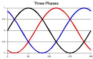
Three phase is three phase because there are three voltage supply lines. Single phase has only one voltage supply line. The neutral line is not a supply line, it's a return.
In the USA, transformers may have a 2.4kV input. The transformer will step down the voltage by a factor of 10/1, giving you a supply of 240V. They then center tap the transformer to give you two 120V supply lines.
Agree with the center tap part.
Delta and wye can be mathematically equated to each other. Delta represents systems that do not contain a neutral line.
A transformer has one phase.
No no no. A difference in voltage does not imply a difference in phase. Every single point on the secondary of that transformer has the same phase angle.
No, when one of the points is at maximum possible voltage, the other point is at maximum negative voltage. It is valid to refer to them as 180 out of phase.
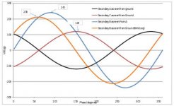
Three phase can also contain a neutral line, providing four lines. Line-to-line voltages in a delta-source can be mathematically converted to their line-to-neutral or phase wye equivalents by dividing by the square root of 3 and subtracting 30 degrees from the phase angle.
Not going to check your math.
NOOOOOOOO. Between two points, a voltage is in reference to another point. If there is +12V between two points, there is +12V at one point and 0V at the other point. If you reverse the direction of your measurement, there will be -12V at the second point and 0V at the first point.
That is true for DC. In AC the voltage is reversing at the line frequency. No one is reversing the direction of the measurement. The current wants to go in the opposite direction.
Also, again voltage and phase shift are two entirely different concepts! Every point on that secondary is at one phase!
Put two of those 2 taps on a two channel scope with a tap between them as the ground and the sine waves are clearly 180 out of phase. No question of that.
The supplies across the secondary coil of that transformer will always have the same phase. Different loads will have different phase angles depending on the inductance or capacitance of the loads. The phase angle could be anywhere between 0 and 360 degrees.
This reply not accurate because it is incomplete. Loads may have a phase angel between the VOLTAGE being fed to them and the CURRENT they draw.
..it does not have to be strictly 0 or 180 degrees.
Edit: Clearly this was not a silly question, because a lot of people here have misconceptions about what voltage and phase angle are and how they work. That's totally understandable, as they're highly mathematical concepts. I'll be more than happy to answer more questions for you guys, but I'm drunk
Agree. ")
and tired and need to be up early, so I'll check back here tomorrow evening.