Provincial
Well-known member
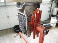
I made a simple tool yesterday. It is an adapter to mount a Honda GX620 engine on my engine stand. I wanted to hold the engine away from the adjustable arms of the stand and also be able to use 5/16 bolts to mount the engine to the stand.
It consists of two pieces of 2x2x1/4 angle iron 10" long each with two 1/2" holes drilled to match the spacing of the stands adjustable arms when placed horizontal and parallel. I mounted these pieces vertical and spaced the inboard leg just under 12" apart, parallel to each other and with the upper ends even.
I then cut two pieces of 1/4x2 flat bar 12" long and drilled two 3/8" holes to match the spacing of the width of the mounting bolts of the engine. These holes were centered on the bar and 3/4" from one edge.
I welded the first flat bar even with the top of the angle iron. I then spaced the lower bar to put the holes the correct distance from the first holes, matching the bolt pattern of the engine.
When I laid out the holes in the flat bar, I scribed the locations very large, so the scribe lines extended far past the holes after they were drilled. This allowed me to use a square and rule to verify that the holes were spaced properly and square.
It was a simple project, but made working on the engine very easy. I made an adapter some time ago to work on a Ford 4R100 transmisson. It is shown in the second photo.
It consists of two pieces of 2x2x1/4 angle iron 10" long each with two 1/2" holes drilled to match the spacing of the stands adjustable arms when placed horizontal and parallel. I mounted these pieces vertical and spaced the inboard leg just under 12" apart, parallel to each other and with the upper ends even.
I then cut two pieces of 1/4x2 flat bar 12" long and drilled two 3/8" holes to match the spacing of the width of the mounting bolts of the engine. These holes were centered on the bar and 3/4" from one edge.
I welded the first flat bar even with the top of the angle iron. I then spaced the lower bar to put the holes the correct distance from the first holes, matching the bolt pattern of the engine.
When I laid out the holes in the flat bar, I scribed the locations very large, so the scribe lines extended far past the holes after they were drilled. This allowed me to use a square and rule to verify that the holes were spaced properly and square.
It was a simple project, but made working on the engine very easy. I made an adapter some time ago to work on a Ford 4R100 transmisson. It is shown in the second photo.